ALFAtron ALF-DSP88-U User manual

ALF-DSP88-U
-2-
Table of Contents
1. Hardware .......................................................................................... 5
1.1 Safety Instructions....................................................................................................................................5
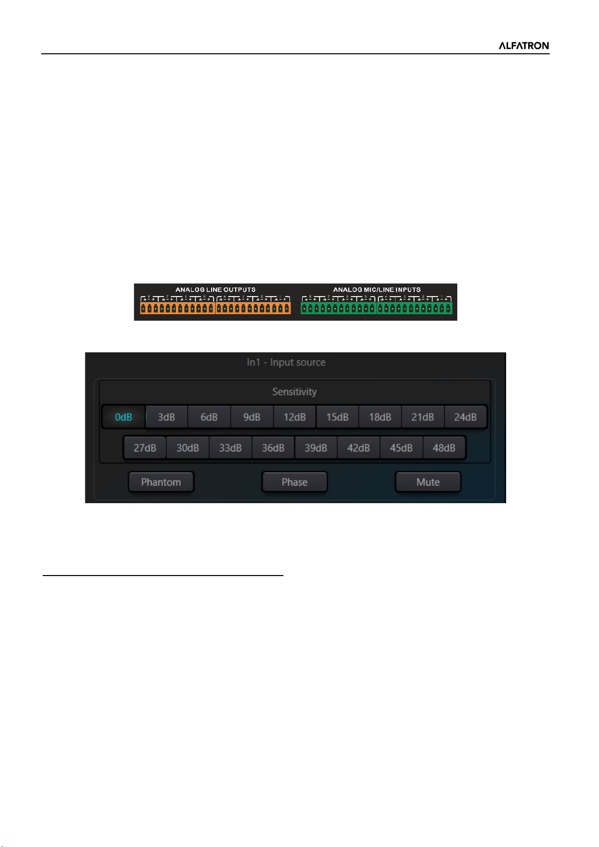
1.2 Audio Wiring Reference ...........................................................................................................................6
1.3 Specifications ...........................................................................................................................................7
1.4 Mechanical ...............................................................................................................................................8
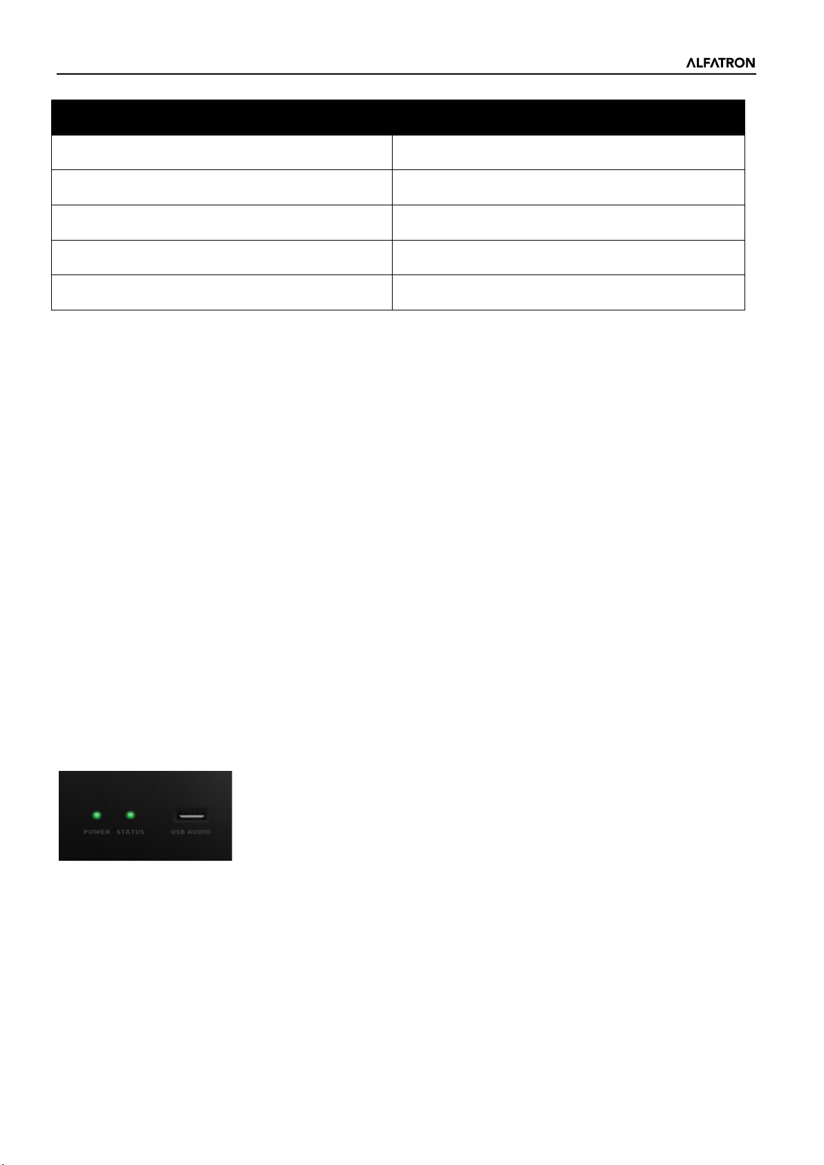
1.5 Front Panel ...............................................................................................................................................8
1.6 Rear Panel................................................................................................................................................9
2. Technology Overview ....................................................................... 9
2.1 Introduction to DSP Technology ..............................................................................................................9
2.2 Audio Input Section ................................................................................................................................10
2.3 Audio Output Section ...........................................................................................................................111
2.4 Floating Point DSP...............................................................................................................................111
2.5 Audio Flow............................................................................................................................................133
2.6 Typical System Application ..................................................................................................................144
3. Software........................................................................................ 155
3.1 Software Installation.............................................................................................................................155
3.2 Using the Software.................................................................................................................................16
3.3 Audio Module Parameters......................................................................................................................16
3.3.1 Input Source ..................................................................................................................................177
3.3.2 Expander .......................................................................................................................................177
3.3.3 Compressor & Limiter......................................................................................................................19
3.3.4 Automatic Gain Control ...................................................................................................................20
3.3.5 Equalizers........................................................................................................................................21
3.3.6 Feedback Suppressor .....................................................................................................................22
3.3.7 AutoMixer.........................................................................................................................................24
3.3.8 Acoustic Echo Cancelation..............................................................................................................25
3.3.9 Noise Suppression ..........................................................................................................................26
3.3.10 Matrix .............................................................................................................................................26
3.3.11 High & Low Pass Filter ..................................................................................................................27
3.3.12 Delay..............................................................................................................................................28
3.3.13 Output ............................................................................................................................................28

ALF-DSP88-U
-3-
3.3.14 USB Interface ................................................................................................................................28
3.4 Setting Menu ..........................................................................................................................................30
3.4.1 File Menu.........................................................................................................................................30
3.4.2 Device Setting .................................................................................................................................31
3.4.3 GPIO Setting....................................................................................................................................31
3.4.4 Group Setting ..................................................................................................................................34
3.4.5 Panel Setting ...................................................................................................................................35
3.4.6 Help Menu .......................................................................................................................................37
4. Control ............................................................................................ 38
4.1 External Control Programmer ................................................................................................................38
4.2 Control Protocol......................................................................................................................................38
4.3 Serial Port-to-UDP (RS232 To UDP) .....................................................................................................40
5. FAQs............................................................................................... 41
Appendix A: Module ID Distribution .................................................... 42
Appendix B: Module Parameter Types (1).......................................... 43
6. After-Sales ...................................................................................... 45
7. Warranty.......................................................................................... 46

ALF-DSP88-U
-4-
Preface
Read this user manual carefully before using the product. Pictures shown in this manual are for reference
only. Different models and specifications are subject to the real product.
This manual is only for operational instruction, please contact the local distributor for maintenance
assistance. The functions described in this version are updated as of September 2021. In the constant effort
to improve the product, we reserve the right to make functions or parameters changes without notice or
obligation. Please refer to the dealers for the latest details.
FCC Statement
This equipment generates, uses, and can radiate radio frequency energy and, if not installed and used in
accordance with the instructions, may cause harmful interference to radio communications. It has been
tested and found to comply with the limits for a Class B digital device, pursuant to part 15 of the FCC Rules.
These limits are designed to provide reasonable protection against harmful interference in a commercial
installation.
Operation of this equipment in a residential area is likely to cause interference, in which case the user at
their own expense will be required to take whatever measures may be necessary to correct the interference.
Any changes or modifications not expressly approved by the manufacturer would void the user’s authority to
operate the equipment.
Do not dispose of this product with the normal household waste at the end of its life cycle. Return it to a
collection point for the recycling of electrical and electronic devices. This is indicated by the symbol on the
product, user manual or packaging. The materials are reusable according to their markings. By reusing,
recycling or other forms of utilisation of old devices you make an important contribution to the protection of
our environment. Please contact your local authorities for details about collection points.

ALF-DSP88-U
-5-
1. Hardware
1.1 Safety Instructions
Safety Instructions
Important safety instructions:
1. Read these instructions.
2. Keep these instructions secure.
3. Pay attention to all warnings.
4. Follow all instructions.
5. Please keep the device away from water. The device cannot be exposed to water drips or water splashes; make
sure that there is no object with liquid near the device, such as a vase.
6. Please use dry cloth to clean the device.
7. Please do not block the vent. Please install the device based on the manufacturer's instructions.
8. Please do not install near any heat source, such as radiator, furnace, or other devices (including amplifiers) that
generate heat.
9. Please make use of a protective grounding connection to connect the device to the power socket. Please do not
use polarized plug or grounding plug. A polarized plug has two leaves, and one is wider than another. A grounding
plug has two leaves and a third ground terminal. The wide leaf or third ground terminal can provide safety for the
users. If the plug provided does not correspond with the power socket, please contact an electrician to replace the
old socket with a new one.
10. Protect the power cord so that it will not be trampled or jutted, particularly the plug, the socket and the
connections of cord and device.
11. Please use the accessories designated by the manufacturer.
12. Please only use a cart, a tripod, or a desk designated by the manufacturer, or sold together with the device. When
using a cart, please take care with the mobile cart / device to avoid injury from rollover.
13. Please unplug the device during a thunderstorm or during the idle period.
14. Please contact our qualified maintenance personnel to deal with all maintenance related issues. For example, the
power cord gets damaged, liquid has spilt over, or an object falls onto the device; the device is exposed to rainwater
or moisture; the operations are not correct, or the device completely fails.
The lightning logo (an equilateral triangle with an arrow) is used to make the users aware of the uninsulated
"dangerous voltage" within the product shell, which may cause electric shock. An equilateral triangle with an
exclamation mark is adopted to make the users understand the importance of the operations and maintenance
instructions given in the appendixes attached to the product.
Warning: In order to prevent electric shock, please do not use a polarized plug provided by a device with an
extension cord. The socket outlet cannot be inserted except for the sharp end.

ALF-DSP88-U
-6-
1.2 Audio Wiring Reference
Balanced Audio Connection
Any of these audio connections may occur on either input or output terminals.
Unbalanced Audio Connection
RCA audio connections and 1/4-inch TS audio connections are unbalanced connections. A multi-strand shielded
conductor may be installed on both ends of the unbalanced connection. In such a case, please note to join the
negative and shield conductors as indicated.

ALF-DSP88-U
-7-
1.3 Specifications
Alfatron ALF-DSP88-U
SPECIFICATIONS
Processor ADI SHARC 21489(x2)
Sampling rate/Digitalizing bit 48K/24bit
Input Gain 0 – 48dB in 3dB Steps
Phantom Power 48V
Frequency Response (20~20KHz) ±0.2dB
Maximum Level +24dBu
THD + Noise 0.003%@4dBu
Dynamic Range 110 dB
Background Noise (A-weighted) -91 dBA
Common Mode Rejection Ratio @60Hz 80dB
Channel Isolation @1KHz 108 dB
Input Impedance (Balanced Connection) 9.4KΩ
Output Impedance (Balanced Connection) 102Ω
System Delay <3ms
Inputs 8 Balance Line/Mic Inputs on Phoenix Connections
Outputs 8 Balance Line Outputs on Phoenix Connections
Audio Processing Functions
Acoustic Echo Cancellations (AEC)
Automatic Gain Control (AGC)
Noise Suppression
Auto Mixer
Matrix
8 Band Parametric EQ (Inputs & Outputs)
High / Low Shelf Filters
Expander
Compressor / Limiter
Feedback Suppressor
Delay
USB AUDIO
1 In – 1 Out
Control Options
IP based PC software and host control.
Third party control for RS-485 and RS-232.
GPIO
8 Channel Logic Output

ALF-DSP88-U
-8-
1.4 Mechanical
Space required:
1U (width * depth * height: 18.91″ x 9.5″x 1.72″ / 48.02 cm x 24.13 cm x 4.37 cm). The reserved head space is not
included in the depth.
An additional space at least 3 inches must be reserved for the connection of rear panel. The reserved depth depends
on the wire used and the connection mode.
Electrical Properties:
Maximum universal input power: 110-240 VAC, 50/60 Hz, 40 W.
Ventilation:
The recommended highest operating ambient temperature is 30℃/ 86℉.
Make sure that there is no obstruction on both sides (a gap of at least 5.08cm / 2 inches shall be reserved). Please do
not cover the thermal vents of the device with newspapers, a tablecloth, or any other objects.
1.5 Front Panel
Power: LED power indicator.
STATUS: The operational status indicator of the device.
USB AUDIO: USB soundcard (1-in-1-out), for connection to host PC.
MECHANICAL
Working Power AC110~240V 5Hz-60Hz
Maximum Power Consumption <40W
Rack Space Required 1U
Dimensions (Width x Depth x Height) 482 x 260 x 45mm
Shipping Weight 3KG

ALF-DSP88-U
-9-
1.6 Rear Panel
Power Source:
Power switch
Fuse
Power connector: (Supports 110 - 240V AC 50/60Hz, and supports a maximum power of 40W)
Ethernet Connector
10/100 Base-T Ethernet connector is used for IP-based PC software and host control, and third-party accessory
controller.
RS485
Used for the serial communication port Tx = sending or data output or Rx = receiving or data input that connects
to a third-party control device.
RS485 can be used for voice tracking control (or other output commands), or for bus input control. A central
command can be used to conveniently integrate it into your software.
Port setting: 115200 baud (default), 8 data bits, 1 stop bit, no parity, no flow control.
RS232
Used for serial communication; port Tx = sending or data output or Rx = receiving or data input that connects to
a third-party control device.
Port setting: 115200 baud (default), 8 data bits, 1 stop bit, no parity, no flow control.
GPIO
12-bit 3.81 mm terminal
8-channel logic output, with 4 pairs of universal grounding pins. After being activated, the logic output will be
low (0V), and the internal voltage will be high (5V) when not activated. You may directly power and light up
external LEDs. The logic output can be driven by the logic output control module in the device design. Polarity
and threshold can be set in the software.
2. Technology Overview
2.1 Introduction to DSP Technology
Audio Digital Signal Processors (DSP) are equipped with several core technical features to simulate the work of
an audio engineer. DSP-based audio management, routing, processing, and control is facilitated via a computer
running the GUI Software for the Audio DSP Hardware. This Manual mainly introduces the techniques used to
achieve this goal.
The Alfatron DSP Controller software is a Windows-based application, which is used to configure and control the
DSP hardware. The Alfatron DSP Controller has 16 built-in presets, and the modules and sequences for each
preset can be flexibly designed in accordance with the designer's requirements. Once the design is completed,
it can be saved for future use. The sequences and parameters of the DSP Controller's built-in processing
modules work with most application scenarios without needing any changes.

ALF-DSP88-U
-10-
The Alfatron DSP Controller is a full-feature application, including parameter adjustments and peripheral
accessory settings of all modules, such as RS232, RS485, and click-and-drag panel configuration etc. The most
interesting part is the user interface, which allows the engineer to customize the user interface so that the
integrator can edit it, or the onsite technicians or end users who have no idea of the relevant techniques can
operate it. Advanced security features make it possible for the end user to only access the controls allowed by
the engineer, or designer.
2.2 Audio Input Section
The Alfatron ALF-DSP88-U supports up to 8 fixed analogue audio inputs, which can be connected via removable
balanced phoenix connectors. The analogue input section supports microphone or line-level signals whose
nominal levels range from 0dBu to +48dBu in 3dBu steps.
+48VDC phantom power can be independently switched on/ off for each input.
Preamp gain and phantom power can be conveniently controlled via the DSP Controller.
The Analogue to Digital (A/D) converter, or ADC, adopts an advanced 24-bit 256X sampling converter.
Analogue to Digital (A/D) Converter Technical Specs:
Sampling rate: 48kHz
THD+N: 105dB
Dynamic range: 120dB
Audio format: 24Bit MSB TDM

ALF-DSP88-U
-11-
2.3 Audio Output Section
The Analogue output section refers to the digital to analogue (D/A) converter, or DAC, also adopts an advanced
24-bit 256X sampling converter. Just like the A/D converter, it also uses multi-bit architecture for broader
dynamic range. Unit gain (0dB) is set via volume control, and the analogue output section is corrected as +4dBu
with 20dB headroom. That is to say that 0dBFS digital signal is equivalent to +24dBu output signal. If other signal
levels are required, you may change the output volume to achieve it.
Digital to Analogue (D/A) Technical Specs:
Sampling rate: 48kHz
THD+N: -100dB
Dynamic range (A-weighted): 118dB
Audio format: 24Bit MSB TDM
On the software output interface there are two controls: Phase and Mute.
Phase: The phase button inverts the phase of the output signal by swopping the polarity.
Mute: Mutes the analogue output of the respective channel
2.4 Floating Point DSP
The ALF-DSP88-U adopts analogue devices’ ADI SHARC audio processors, enabling 32-bit and 40-bit floating-
point processing, which can be compared to 40-bit floating-point processing of other devices. Floating-point
processing provides prominent advantages for the users in terms of sound quality and usability.
Fixed-Point Processing Limitations
Fixed-point processing has its own disadvantages. If there is a significant change in gain, data loss or a more
severe error may occur, including clipping or distortion. For example, the processing of 24-bit fixed point-based
audio signal, in some cases, if you attenuate the signal to 42dB, the new signal only includes 17-bit information.
Due to gain attenuation, 7 bits of information will be lost forever. Worse than that is the clipping distortion. For
a signal nearly close to 0dBFS, the signal will be clipped at 0dBFS, and audio distortion will occur. Even if the
signal level is adjusted to below 0dBFS through post-regulation, the clipping has occurred, and the distortion still
exists. Fixed point processing can create some headroom above 0dBFS, but by doing so, some bits have to be
abandoned. For example, if a 12dB (2 bits) headroom is created, a 24-bit system will only have 22 bits.

ALF-DSP88-U
-12-
Floating-Point Processing
On the contrary, by taking advantage of floating-point processing, no matter what the signal level is, all available
bits are uniformly distributed to the signals. Basically, the floating points use some bits as indexes to set up
general signal level and distribute the remaining bits to signals with independently stored level. As a result, no
matter what kind of level (from -200dB and 200dB below to 0dBFS above, the stored signal's accuracy is
optimized without clipping distortion. SHARC provides 32-bit and 40-bit accurate processing; through 32-bit
processing, 25 bits are distributed to storage signals no matter what its signal level is. This means that, based on
at least 1-bit low level signal, its accuracy is always significantly superior to 24-bit fixed point processing.
Through expanded 40-bit accurate processing, 33-bit storage signals can be achieved.
Practical Significance
What's the practical significance of floating-point processing for the users? The gain stages between multiple
modules can be ignored. If the signal level of a module is reduced by 50dB and is then restored to its original
value through another processing, data loss will not occur. In the fixed-point system, the users must check other
signal levels before sending it to the A/D converter because all digital-to-analogue converters adopt fixed points.
In the DSP system, if you notice that your signal has been clipped before it is outputted and transmitted to the
digital-to-analogue converter, you may close it off immediately at the output section to correct the situation. If
using the fixed-point system, you would have to search each processing module to find the clipping source.

ALF-DSP88-U
-13-
2.5 Audio Flow

ALF-DSP88-U
-14-
2.6 Typical System Application
Conferencing System: The processor can be connected to microphones, amplifiers, speakers, and other audio peripherals
(like USB audio from a PC) so as to process all audio signals and advanced algorithms like AEC in a typical conferencing
system. Additional audio matrixing, auto mixing and signal routing is also achieved in this application to facilitate excellent
audio quality in a conference.

ALF-DSP88-U
-15-
3. Software
3.1 Software Installation
A Windows PC with:
• Intel i5 processor or higher
• 8 GB or higher memory
• 1 GB free storage space
• Windows 7 or higher version
• Minimum 1920 x 1080 resolution
• 24 bit or higher color
• Network (Ethernet) port
Software Installation:
Visit the device web page address: 169.254.10.227
1. Download software from the Alfatron website and install files.
2. Double click the downloaded file and install by following the instructions on the screen.
After the software is installed, read other parts of the help file, or execute the software.
After the software is installed, use one of the following methods to open the software:
1. Double Click Desktop Icon
2. Open from Start menu

ALF-DSP88-U
-16-
3.2 Using the Software
After enabling the software, the main menu is shown as below:
Click the button in the right corner of the main menu to find all processors on the network automatically.
The user may connect to the designated processor based on their own needs; after the connection, the indicator will flash;
each processor supports simultaneous connection and control for up to four users.
3.3 Audio Module Parameters
There are two ways to access the audio module parameters: first, click the input or output channel module you wish to
access, and enter the parameter interface of the module; secondly, right click the channel module and the configuration
interface will pop out. This is used for the following module parameters.

ALF-DSP88-U
-17-
3.3.1 Input Source
Sensitivity: Microphone gain, 0dB - 48dB in 3dB Steps.
Phantom Power: Provides +48V phantom power for external condenser microphones. (Do not enable phantom power when
the power is not required, this is to prevent damaging any non-Phantom powered devices when connected.)
Sine Wave: Select the Sine Wave button and drag the frequency to generate sine wave with selected frequency (selectable
20Hz - 20 kHz). You may regulate the output level (unit: dBFS) based on your requirements. Use the level fader to adjust or
click the text field to designate a value.
White Noise: When observed on the frequency spectrograph with constant bandwidth, and set to a flat frequency spectrum,
white noise signal has equal energy across all frequencies.
Pink Noise: The frequency intensity level of pink noise is mainly distributed in the middle and low frequency bands. It
decreases with a speed of 3dB/Oct in the middle and low frequency bands.
In addition, you may also find the following menu by right clicking each fader on the main menu.
Group Setting: Open the group setting interface window.
Minimum and Maximum Gains: Limit the maximum and minimum values of a channel. After it is commissioned, if you do
not wish that the system's stability is affected due to external factors, you may set up a maximum gain.
3.3.2 Expander
Although similar in concept, the expander has a different operating principle from the compressor. It can expand the
dynamic range of a signal. The most fundamental difference in these two devices lies in that, the compressor works on the
signal higher than the threshold, while the expander works on the signal lower than the threshold. Louder and softer signals
become relatively louder and softer respectively. It can be seen from Fig.3.2 that, when the expansion ratio reaches 1:2, the
input signal 20dB lower than the threshold will generate an output signal 40dB lower than the threshold. Thus, as shown
below, the signal lower than the threshold will extend downwards and cause softer level. When an expansion ratio 1:20 is
adopted. The expander seems to be a noise gate in terms of the transmission features. In fact, a noise gate is an expander
with a great expansion ratio.

ALF-DSP88-U
-18-
Fig.3.2 Expander
The expander has the following control parameters:
Threshold: The expander activates only when the signal exceeds this threshold (allowing the transmission of the signal). As a
standard practice, the signal is often set at the ambient noise level
Ratio: Ratio refers to the slope below the threshold point on the gain curve. When the slope is set at a high level, gating will
activate.
Attack:Attack refers to the time that the expander will wait before activating when the input signal exceeds the threshold.
Shorter attack time allows to start the expander more quickly.
Release time: Release time refers to the delay in time required for the gain to be restored to normal when the input signal
drops lower than the threshold.
No matter the starting time or the release time, it just helps to reduce the speed of gain attenuation. That is to say, the
speed of the gain from -40dB to 0dB is slowed down due to the influence of Attack. The Attack time and Release time is
unrelated to the threshold. If the signal level falls below the threshold, the Attack time and Release time will have their own
respective influence on gain attenuation; when the signal level rises above the threshold, the gain attenuation produced by
the expander will disappear in accordance with the speed controlled by the Release time. When the gain attenuation is
reduced to 0dB, the expander will stop expansion. Later, when the signal reduces to below the threshold, the expander will
start again, and the release time will begin to work.

ALF-DSP88-U
-19-
3.3.3 Compressor & Limiter
Compressor
The compressor is used to reduce the dynamic range of the signal higher than the threshold set by the user, and to maintain
the dynamic range of the signal lower than the threshold. The compressor has the following control parameters:
Threshold: When the signal level is higher than the threshold, the compressor / limiter begins to reduce the gain. Any signal
that exceeds the threshold is regarded as overshoot signal, and its level will be reduced based on the ratio set. The more the
signal level exceeds the threshold, the more level is attenuated.
Ratio: It refers to the compression ratio. The ratio sets the attenuation degree of the overshoot signal to the threshold level.
The smaller the compression ratio is, the less compression will take place and signal will remain higher than the threshold.
Once the signal exceeds the threshold, the compression ratio decides the ratio of input signal variation to output signal
variation. For example, when the compression ratio is 1:2, if the input signal is 2dB higher than the threshold, the exceeding
part only changes by 1dB. A compression ratio of 1:1 suggests that the compressor does not attenuate the signal in
proportion. The adjustable range of compression ratio is 1-20.
Attack Time & Release Time: In order to maintain natural oscillation, it is generally accepted that part of the original level
will pass through the compression without any influence, or just minor influence. Likewise, if there is rapid sharp attenuation
and rapid recovery in the signal gain, the suction effect will occur. The attack and release time of the compressor is to avoid
this effect. The attack time sets the speed of gain attenuation, while the release time sets the speed of gain recovery.
Output Gain: Also called gain compensation. If the compressor significantly reduces the level of the signal, it may need to
enhance the output gain to maintain the volume. Output gain applies to all parts of the signal and is unrelated to other
parameter settings of the compressor.
Gain Reduction (G.R.) and output Level Meter: G.R. indicates the compressor's compression amount; output refers to the
output level of the signal that has passed through the compressor module (post compression). The compression amount is
displayed in an inverse level meter. If the input signal and threshold are set as -6dB and -30dB, respectively, and the ratio is
2:1, then the compression amount is 12dB; the G.R. level meter indicates around -12dB and output indicates around -18dB.

ALF-DSP88-U
-20-
Limiter
The limiter only has one key task: make sure that the signal will not exceed the threshold level in any way. By adjusting the
compressor's control parameters, its working modes will be very similar to those of the limiter. The core working principle of
a limiter is that it focuses on the signal below the threshold level as well as how the gain attenuation is produced before the
occurrence of overshoot signal. The limit period consists of two processing stages: during the first stage, there is a minor
limit, but the overshoot signal will not be processed; during the second stage, if there is overshoot signal, it will attenuate
with a very high ratio.
The limiter only provides two parameters: Threshold and Release Time. In terms of signal processing, occasional clipping will
be solved with a limiter, while the signal level will be attenuated in terms of frequent clipping.
3.3.4 Automatic Gain Control
Automatic gain control (AGC) is a type of compressor. Its threshold is set at a very low level with middle-to-slow attack time,
long release time, and low ratio. The purpose is to improve the signal with an uncertain level to a target level, while
maintaining the dynamic range at the same time. Most of the auto gain control includes silent detection to prevent the gain
attenuation loss during the silent period. This is the only function that distinguishes auto gain control from an ordinary
compressor / limiter.
Auto gain control may be adopted to normalize the level of CD players that play background music, foreground music and
music on hold, as to eliminate the changes in the level of some paging microphones.
Table of contents
Other ALFAtron Recording Equipment manuals
Popular Recording Equipment manuals by other brands

Omega Engineering
Omega Engineering OMB-CHARTSCAN 1400 user guide

Rebis Audio
Rebis Audio RA226 user guide

Cary Audio Design
Cary Audio Design Cinema 11 owner's manual

Omron
Omron SYSMAC NX-CIF Series user manual

ALLEN & HEATH
ALLEN & HEATH DR66 Service manual

Avid Technology
Avid Technology DigiDesign Surround Panner Option Guide