Quick start guide
This document contains installation instructions
for the E-Socket. Please always refer to our
website for the most up-to-date and complete
manual for the product.www.alfen.com/en/
downloads.
The installation must comply with standards
and (local) regulations and must only be carried
out by a qualified technician.
The electrical system must be disconnected
from every power source before performing any
installation or maintenance work!
This manual describes the installation of the E-
Socket for both the Eve Double Pro-line FR and
the Eve Single Pro-line FR simultaneously.
Conditions of use
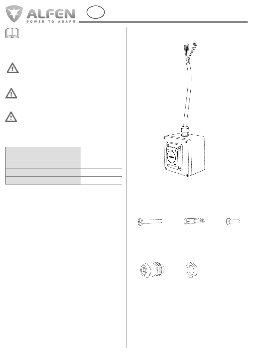
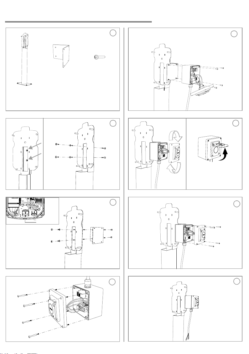
Package contents
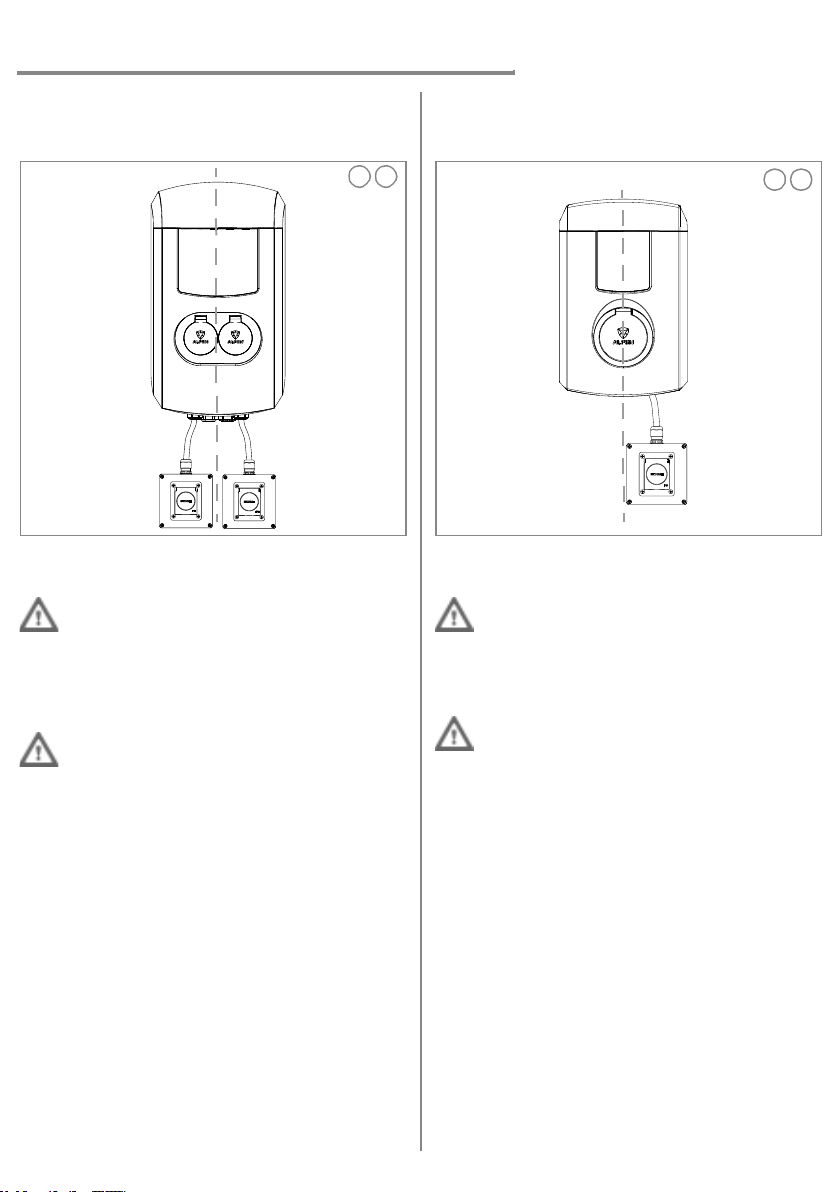
Connecting the E-Socket to the
Eve Double Pro-line FR
The E-Socket on the Eve Double Pro-line FR
A total of two E-Sockets can be installed on the
Eve Double Pro-line FR.
1Determine the position of the E-Socket(s):
•Left and/or
•Right.
The E-Socket cannot be mounted on the Eve
Double Pro-line FR. Do not leave the E-Socket
hanging.
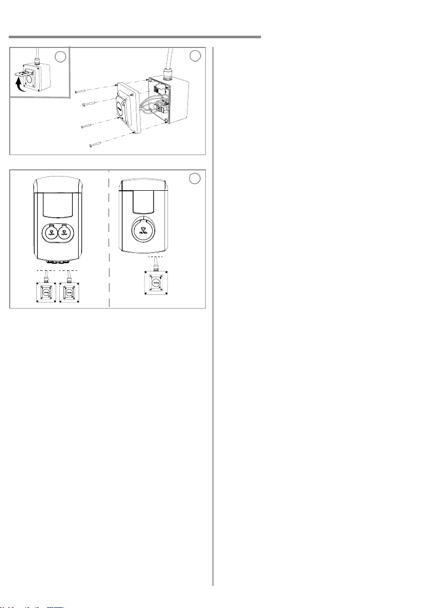
2Example of the assembled E-Socket:
•Right side assembly.
•Left side assembly.
Use the proper mounting material or kit for
installation:
Wall mounting:
•The wall mounting screws and plugs are included in
the E-Socket package.
Mounting E-Socket on the Eve Double pole:
•Eve Double pole FR (934459002).
•The E-Socket Support pole Eve Double
(803873064-ICU).
Connecting the E-Socket to the
Eve Single Pro-line FR
The E-Socket on the Eve Single Pro-line FR
A total of one E-Socket can be installed on the
Eve Single Pro-line FR.
1The E-Socket can only be installed on the right
side of the Eve Single Pro-line FR.
The E-Socket cannot be mounted on the Eve
Single Pro-line FR. Do not leave the E-Socket
hanging.
2Example of the assembled E-Socket:
Right side assembly.
Use the proper mounting material or kit for
installation:
Wall mounting:
•The wall mounting screws and plugs are included in
the E-Socket package.
Mounting the E-Socket on the Eve Single pole:
•Eve Single pole (803873036-ICU).
•The E-Socket Eve Single Pole Bracket (803873063-
ICU).
Mounting the E-Socket on the Eve Single Duo-pole:
•Eve Single Duo-Pole (803873037-ICU).
•The E-Socket Support Duo-Pole (803873066-ICU).
Operating temperature -25 °C /
+40 °C
Relative humidity 5% / 95%
Electrical safety class I
Protection rating IP54
1
Left Right
2
Left Right
1 2
M4x30
Wall mount screw
1E-Socket
1
M25x1.5
Cable gland
M25x1.5
Locknut
1
4 4 4
S6
Wall plug
M4x10
Pole mount
screw
5
E-Socket