ALIARO AL-1020 User manual

1
ALIARO reserve the right to vary from the description given in this data sheet and shall not be liable for any errors.
www.aliaro.com
12 Channels Power Switch Board
AL-1020 for SLSC
This document describes the AL-1020 board for National Instruments SLSC-12001 chassis.
Definitions
This document describes the performance of the described module under specific operating
conditions which are covered by the module warranty.
These conditions can be classified into two main sections:
Typical specifications describe the performance met by most modules.
Nominal specifications describe an attribute that is based on design, conformance
testing, or supplemental testing for this specific module.
Specifications are Typical unless otherwise noted.

2
ALIARO reserve the right to vary from the description given in this data sheet and shall not be liable for any errors.
www.aliaro.com
Conditions
Specifications are valid under the following conditions unless otherwise noted.
The AL-1020 module is mounted in a standard NI SLSC chassis. This chassis should conform to
the NI recommended cooling requirements and use a standard power supply that meets the
specifications provided in the chassis user guide. All aspects of the SLSC chassis should follow
NI guidelines.
Please Note - These specifications only apply to the product as provided by ALIARO.
Modifications to the module may invalidate these.
Caution - Observe all instructions, warnings and cautions in the board
documentation. Using the module in a manner not specified by this document can
damage the module and compromise the built-in safety protection. Return damaged
models to ALIARO for repair.
Overview
The AL-1020 (Power Switch Board) board provides power switching capability (to for example,
test shorts in vehicles) and has fault insertion on all channels that allows users to switch output
between multiple signals.
The AL-1020 board is designed to fit National Instruments (NI) Switch Load Signal Conditioning
(SLSC) system together with corresponding computer interface boards and is delivered with
LabVIEW driver and a Custom Device for VeriStand.
The main purpose of the board is to be used for test and validation of Devices Under Test
(DUTs), testing for both software and hardware failures. This is usually done by incorporating the
board as part of Hardware-In-the-Loop (HIL) test system.
For easy board/system configuration, it is recommended to use the board alongside xMove
Configurator.

3
ALIARO reserve the right to vary from the description given in this data sheet and shall not be liable for any errors.
www.aliaro.com
Content
Definitions ............................................................................................................................................... 1
Conditions................................................................................................................................................ 2
Overview.................................................................................................................................................. 2
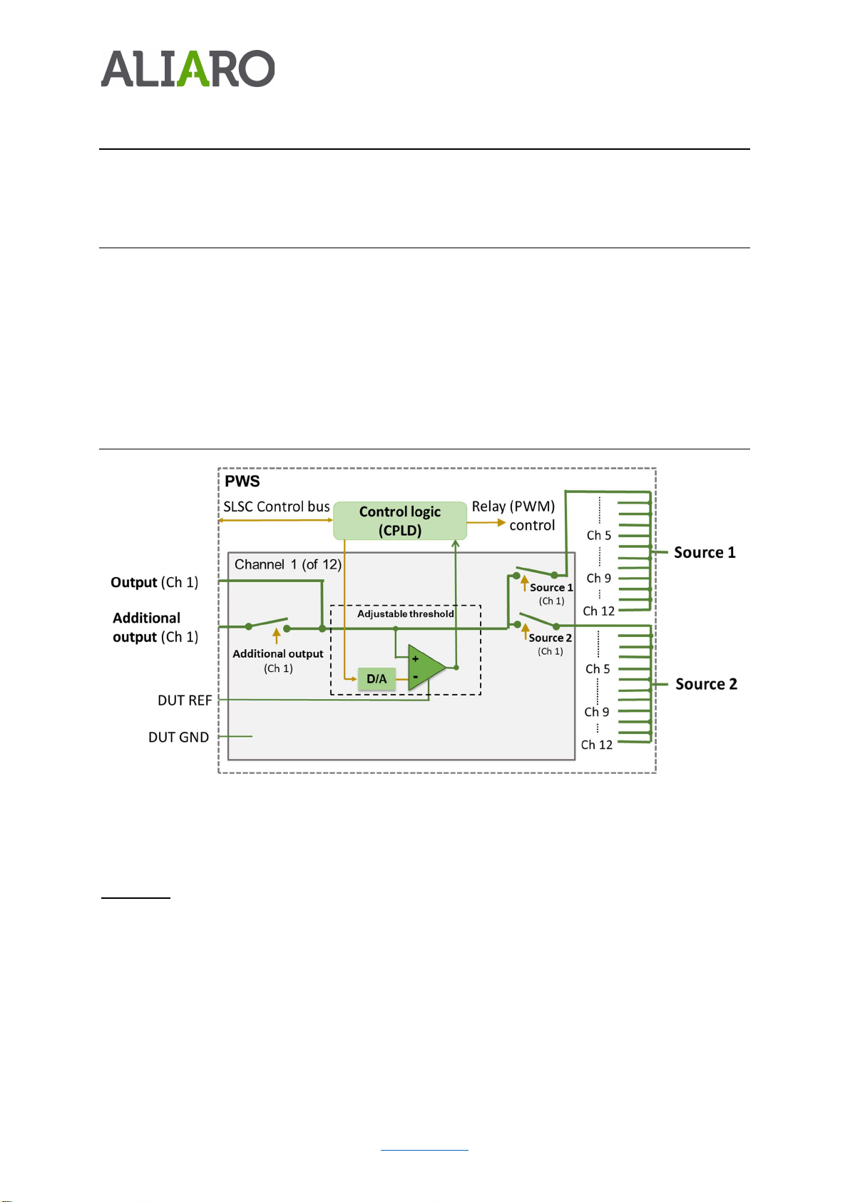
Description .............................................................................................................................................. 4
Features ............................................................................................................................................... 4
Detailed description ............................................................................................................................ 4
Installation ............................................................................................................................................... 5
Electromagnetic Compatibility (EMC) ................................................................................................. 5
Unpacking the module ........................................................................................................................ 5
What You Need to Get Started ............................................................................................................ 5
Installing the AL-1020 .............................................................................................................................. 6
Software Installation - SLSC LabVIEW Drivers ..................................................................................... 7
Software Installation - ALIARO Custom Devices .................................................................................. 7
Software Installation - ALIARO xMove Configurator (Optional) ......................................................... 7
System Check ....................................................................................................................................... 7
Operation ................................................................................................................................................ 7
Safety Guidelines ................................................................................................................................. 7
System check using LabVIEW .............................................................................................................. 8
Maintenance ........................................................................................................................................... 8
Calibration ........................................................................................................................................... 8
Specification .......................................................................................................................................... 10
Environmental Characteristics .......................................................................................................... 10
Physical characteristics ...................................................................................................................... 10
General specification ......................................................................................................................... 10
Safety Guidelines ................................................................................................................................... 10
Product Certifications and Declarations ................................................................................................ 11
CE Compliance ................................................................................................................................... 11
Electromagnetic Compatibility Standards ......................................................................................... 11
Environmental Management ............................................................................................................ 11
Waste Electrical and Electronic Equipment (WEEE) .......................................................................... 11

4
ALIARO reserve the right to vary from the description given in this data sheet and shall not be liable for any errors.
www.aliaro.com
Description
Designed for applications where you need to control the power supply to a Device Under Test
(DUT) as part of a test procedure.
Features
60V, 10A per channel
12 independent and isolated channels in three banks
Two power source buses per bank with switches to each channel
Power On/Off for each channel
Programmable level threshold on each channel
Parallel connection possibility for high current signals
LabVIEW driver included
Detailed description
Figure 1: AL-1020 Block Diagram
The AL-1020 board provides power switching of up to 40A / 60V
Functions:
Twelve channels power switching of two power sources
It is possible to configure channels in parallel (2/4 in parallel) to increase the current
rating (to 20A/40A)
Status monitoring with adjustable threshold
Each channel has an optional additional output that can be switched on/off when
required

5
ALIARO reserve the right to vary from the description given in this data sheet and shall not be liable for any errors.
www.aliaro.com
Installation
Electromagnetic Compatibility (EMC)
This product is intended for use in industrial locations. Harmful interference may occur in certain
installations, such as if the product is used in residential or commercial areas. This may also
occur when the product is connected to a peripheral device or test object that outputs
electromagnetic noise or other interference.
To minimize interference with radio and television reception and prevent unacceptable
performance degradation, install, and use this product in strict accordance with the instructions
of the product documentation.
Furthermore, any modifications to the product not expressly approved by ALIARO may void your
warranty and your authority to operate it under your local regulatory rules.
Caution
-
To ensure the specified EMC performance,
operate this product only with
Shielded cables and accessories.
Unpacking the module
The AL-1020 board ships in an antistatic box to prevent Electrostatic Discharge (ESD). ESD can
damage the device components. Users should be familiar with the steps to prevent ESD damage
when handling the device.
Warning - Never touch the exposed pins of the connectors.
To prevent ESD damage when handling the device, please take the following precautions:
- Ground yourself before handling. Use a grounding strap or by touching a grounded
object.
- Touch the antistatic package to a grounded metal part before removing the device from
the package. A good example would be the metal part of your computer chassis.
Remove the device from the package and inspect it for damages such as loose components.
Contact ALIARO if the device appears damaged in any way. Do not use a damaged device with
any other components. Store the device in antistatic protection when not in use.
What You Need to Get Started
To set up and use the module you need the following items:
Hardware

6
ALIARO reserve the right to vary from the description given in this data sheet and shall not be liable for any errors.
www.aliaro.com
SLSC-12001 chassis
SLSC module(s)
Power cable
Power input connector
Grounding wire
Grounding lug
Tools
Screwdriver as needed for your application
Wire stripper
Documentation
SLSC-12001 Chassis Getting Started Guide and Specifications
Warning - Do not touch the contacts or remove the I/O boards or cables while the
system is energized. The SLSC chassis and the AL-1020 do not support hot plug-in.
The entire chassis must be powered off when a module is inserted or removed.
Installing the AL-1020
Warning - Do not touch the contacts or remove the I/O boards or cables while the
system is energized.
1. Power off the main DC power source or disconnect the power source from the chassis
before installing any modules or RTIs.
2. Ensure that the chassis is powered off. The POWER LED should be off. If the POWER
LED is not off, do not proceed until it is off.
Please Note - The SLSC chassis and the AL-1020 do not support hot plug-in. The
entire chassis must be powered off when a module is inserted or removed.
3. Loosen the screws on the upper rear panel of the chassis.
4. Position the RTI backplane at the desired slot and insert the securing screws, but do not
fully tighten them.
5. Insert an AL-1020module into the same slot as its corresponding RTI while firmly holding
the RTI in place until the RTI is fully connected to the module.
6. Repeat steps 4 and 5 for all required RTIs.
7. Fully tighten the screws for all RTIs and the upper rear panel of the chassis. Wait until all
RTIs and modules are installed before fully tightening the screws. This ensures the
proper alignment for future connections between modules and RTIs.

7
ALIARO reserve the right to vary from the description given in this data sheet and shall not be liable for any errors.
www.aliaro.com
8. Fully tighten the two module mounting screws on each newly installed module.
9. Power on the SLSC Chassis
Software Installation - SLSC LabVIEW Drivers
When the module is used with LabVIEW or TestStand, the ALIARO drivers need to be installed.
Contact ALIARO support for the most recent version of our drivers: support@ALIARO.com
Software Installation - ALIARO Custom Devices
When the AL-1020 is used with VeriStand, Custom Devices needs to be installed. Contact
ALIARO support for the most recent version of our Custom Devices: [email protected]om
Software Installation - ALIARO xMove Configurator (Optional)
xMove Configurator is a tool for defining and editing VeriStand System definition files for HIL
(Hardware-in-the-loop) test systems. It is specifically aimed at configuring ALIARO SLSC Multi-
Purpose boards and NI modules.
The configurator uses a Predefined System Configuration file containing the system mapping
and a VeriStand System Definition file defining all hardware. It empowers users to configure and
reconfigure User Channels, Aliases and System Mappings for HIL systems.
For more information on xMove Configurator, check the xMove Configurator webpage on
NI.com.
System Check
Finnish the installation by conducting a system check, see the chapter Operation.
Operation
Safety Guidelines
Operate the ALIARO AL-1032 only as described in this document.
Warning - Do not operate the device in a manner not specified in this document.
Misuse of the device can result in a hazard. You can compromise the safety
protection built into the device if the device is damaged in any way. If the device is
damaged, contact ALIARO for repairs or replacement.
Warning
-
Do not substitute parts or modify the device except as described in this
document. Use the device only with the chassis, modules, accessories, and cables
specified in the product specification.

8
ALIARO reserve the right to vary from the description given in this data sheet and shall not be liable for any errors.
www.aliaro.com
Warning - Do not operate the device in an explosive atmosphere or where there may
be flammable gases or fumes. If you must operate the device in such an
environment, it must be in a suitably rated enclosure.
System check using LabVIEW
This chapter requires the LabVIEW Development Environment and installation of the ALIARO
LabVIEW drivers.
To identify hat the cards are correctly inserted and work properly with the right firmware,
LabVIEW provides basic VI scripts to check SLSC cards mounted in chassis:
1. Open LabVIEW and select “Help” in the top menu bar and press “Find Examples…”.
This opens a new window listing pre-made LabVIEW examples.
2. Switch to the “Search” tab and enter keyword “SLSC” and search.
3. In the new filtered table (to the right) find and select VI called “Configuration.vi”. This
VI can locates all cards that are online in a SLSC chassis.
4. To find the newly inserted cards look for the SLSC chassis IP-address (in the table to
the right).
5. Count the card(s) in the table and verify that all installed cards are being located by
the program (this can be 1 to 11 cards per SLSC chassis).
Maintenance
Power off all connected device before attempting any maintenance. After maintenance is
complete, ensure that the device is fully dry and installed correctly, before powering the system
back on.
Warning - Many components within the chassis are susceptible to static discharge
damage. Service the chassis only in a static-free environment. Observe standard
handling precautions for static-sensitive devices while servicing the chassis. Always
wear a grounded wrist strap or equivalent while servicing the chassis.
Clean dust from the chassis exterior and interior as needed, based on the operating
environment. Periodic cleaning increase’s reliability.
Use a dry, low-velocity stream of air to clean the interior of the chassis. Use a soft-bristle brush
for cleaning around components
Calibration
Recommended warm-up time 30 min
Calibration interval Not required, recommended on system level
Contact ALIARO to schedule calibration services. Additionally, you may be entitled to calibration
if you have a service agreement.

9
ALIARO reserve the right to vary from the description given in this data sheet and shall not be liable for any errors.
www.aliaro.com
If you have purchased a calibration system from ALIARO, we recommend using the system with
your complete ALIARO test system or device, after the specified interval.

10
ALIARO reserve the right to vary from the description given in this data sheet and shall not be liable for any errors.
www.aliaro.com
Specification
Environmental Characteristics
Temperature and Humidity
Operating temperature 0 °C to 40 °C
Storage temperature range -40 °C to 85 °C
Operating relative humidity range 10% to 90%, noncondensing
Storage relative humidity range 5% to 95%, noncondensing
Physical characteristics
Category Condition Value
Module Dimensions Excluding front handle 144.32mm x 30.48mm x 281 mm
(H x W x D)
Front Panel Connector 1 x female Weidmuller 32 high
density
General specification
Category Condition Value
No of channels 12
No of banks 3
Power supply 24VDC, +/-5%
Max. Operating Voltage Any pin + 60V
Min. Operating Voltage Any pin - 60V
Safety Guidelines
Caution
-
Ensure that hazardous voltage wiring is performed only by qualified
personnel adhering to local electrical standards.
Caution - Do not mix hazardous voltage circuits and human-accessible circuits on
the same module
Caution - When device terminals are hazardous (voltage is LIVE), you must ensure
that devices and circuits connected to the device are properly insulated from human
contact.
Caution - All wiring must be insulated for the highest voltage used.

11
ALIARO reserve the right to vary from the description given in this data sheet and shall not be liable for any errors.
www.aliaro.com
Product Certifications and Declarations
Refer to the product Declaration of Conformity (DoC) for additional regulatory compliance
information.
To obtain product certifications and the DoC for ALIARO products, please contact our support
team at [email protected]om
CE Compliance
This product meets the essential requirements of applicable European Directives, as follows:
2014/35/EU; Low-Voltage Directive (safety)
2014/30/EU; Electromagnetic Compatibility Directive (EMC)
2011/65/EU; Restriction of Hazardous Substances (RoHS)
Electromagnetic Compatibility Standards
This product meets the requirements of the following EMC standards for electrical equipment for
measurement, control, and laboratory use:
EN 55011-2009 Industrial, scientific and medical equipment - Radio-frequency
disturbance characteristics - Limits and methods of measurement CISPR 11:2009
EN 55032:2012 Electromagnetic compatibility of multimedia equipment - Emission
requirements CISPR 32:2012
EN 61326-1-2013 Electrical equipment for measurement, control and laboratory use -
EMC requirements - Part 1: General requirements IEC 61326-1:2012
Environmental Management
ALIARO is committed to designing and manufacturing products in an environmentally
responsible manner. ALIARO recognizes that eliminating certain hazardous substances from our
products is beneficial to the environment and to ALIARO customers. For additional
environmental information, refer to the Minimize Our Environmental Impact web page at
ALIARO.com/environment.
This page contains the environmental regulations and directives with which ALIARO complies,
as well as other environmental information not included in this document.
Waste Electrical and Electronic Equipment (WEEE)
EU Customers At the end of the product life cycle, all ALIARO products must be disposed of
according to local laws and regulations.

12
ALIARO reserve the right to vary from the description given in this data sheet and shall not be liable for any errors.
www.aliaro.com
For more information about how to recycle ALIARO products in your region, visit
ALIARO.com/environment/weee
Table of contents
Other ALIARO Switch manuals