ALIEN WELD XM IGBT Series User manual

1
OWNER'S MANUAL
XM IGBT SERIES
MIG/MAG

2
CONTENTS
1. Safety…………………..………………..…………………...…..…….…...………........................................................................................................
3
2. General Description ...………....……...……………….………...….……...……………....................................................................................
4
3. Main Parameter..…...........…….....……………………………..…….…………………..…..................................................................................
5
4. Installation and Structure.……….…..........……………………………….…….………………………………………………………………….…………………
6
5. Operation ……………........…....................…………….………….………..……….………...................................................................................
12
6. Welding parameters table ...............………………….………………………...…...………………………………………………………….……………………
13
7. Caution………………..……...…..……….…..………………….….……………………….............................................................................................
15
8. Maintenance…………………………………………………………………………………...........................................................................................
16
9. Daily checking…………………………………………………………………………………........................................................................................
17
This welding machine for industrial and professional use is in conformity with IEC974 International Safety Standard.
Hereby we state that we provide one year of guarantee for this welding machine since the date of purchase.
Please read and understand this instruction manual carefully before the installation and operation of this machine.
The contents of this manual may be revised without prior notice.

3
1.SAFETY
Welding and cutting is dangerous to the operator, people in or near the working area, and the surrounding, if the machine is
not correctly operated. Therefore, the performance of welding/cutting must only be under the strict and comprehensive
observance of all relevant safety regulations. Please read and understand this instruction manual carefully before the
installation and operation.
2. GENERAL DESCRIPTION
· The switching of function modes is possibly damaging to the machine,
while the welding operation is performed.
· Do disconnect the electrode-holder cable with the machine, before the
performance of welding.
· A safety switch is necessary to prevent the machine from electric
leakage.
· Welding tools should be of high quality.
· Operators should be qualified.
ELECTRIC SHOCK: IT COULD BE FATAL!
·Connect the earth cable according to standard regulation.
·Avoid all contact with live electrical parts of the welding circuit,
electrodes and wires with bare hands. It is necessary for the operator to
wear dry welding gloves while he performs the welding task.
·The operator should keep the working piece insulating from
himself/herself.
SMOKE AND GAS GENERATED WHILE WELDING OR CUTTING: HARMFUL TO
PEOPLE’S HEALTH.
·Avoid breathing the smoke and gas generated while welding or cutting.
·Keep the working area well ventilated.
ARC RAYS: HARMFUL TO PEOPLE’S EYES AND SKIN.
·Wear welding helmet, anti-radiation glass and work clothes while the
welding operation is performed.
·Measures also should be taken to protect people in or near the working
area.
FIRE HAZARD
·The welding splash may cause fire, thus remove flammable material away
from the working place.
·Have a fire extinguisher nearby and have a trained person ready to use it.
Noise: possibly harmful to peoples’ hearing.

4
2.GENERAL DESCRIPTION
This welding machine is composed of the inverter MIG welder power supply with invariable voltage output external
characteristics manufactured with advanced IGBT inverter technology designed by our company.
With high-power component IGBT, the inverter converts the DC voltage, which is rectified from input 50Hz/60Hz AC voltage,
to high frequency 20KHz AC voltage; as a consequence, the voltage is transformed and rectified. The features of this machine
are as follows:
●IGBT inverter technology, current control, high quality, stable performance;
●Closed feedback circuit, invariable voltage output, great ability of balance voltage up to ±15%;
●Electron reactor control, stable welding, little splash, deep molten pool, excellent welding bead shaping;
●Fit for welding the thin plate which over 0.8mm
●Slow wire feeding during arc starting, remove the melting ball after welding,reliable arc starting;
●Small volume, light weight, simple operation, economical and practical.
Block Diagram
INPUT
CONTROL

5
3. MAIN PARAMETER
Model
XM250 (MIG 250A)
XM300 (MIG 300A)
Power supply voltage (V)
3-phase
220V15%
Input current (A) Imax
17
20
Power supply capacity (KVA)
8.3
12
Current adjustment range (A)
60-250
60-300
Output voltage (V)
15-26.5
15-29
Rated duty cycle (%)
52-56
52-56
Current adjustment range (A)
60
Power factor
0.93
Efficiency (%)
85
Wire feeder type
integrated
Water-cooled
NO
Post-flow time (s)
1-2S
Welding wire diameter (mm)
0.8\1.0\1.2
0.8\1.0\1.2\1.6
Insulation class
F
Protection class
IP21
Workpiece thickness (mm)
≥0.8
Machine dimension(mm)
875*420*807
Package dimension(mm)
990*650*1010

6
4. INSTALLATION AND STRUCTURE
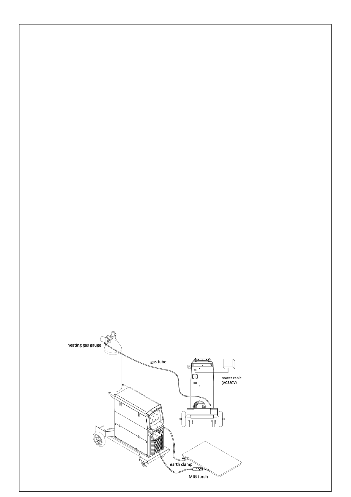
4.1. Input wire connection
Each welder is equipped with connection box, connect the power line with the power source 220V.
4.2. Output wire connection
Connect the gas bottle (equipped with the CO2 flow gauge) and the gas inlet with gas tube.
4.2.1 Connect the terminal of the earth clamp with the negative output, another side is clamped on the workpiece
4.2.2 Connect the MIG torch with the output terminal on the wire feeding machine, insert the welding wire through the
MIG torch manually.
4.2.3 Connect the wire feeding machine input cable with the positive terminal of power source. The control cable of wire
feeding machine should be connected with the control connector of power source.
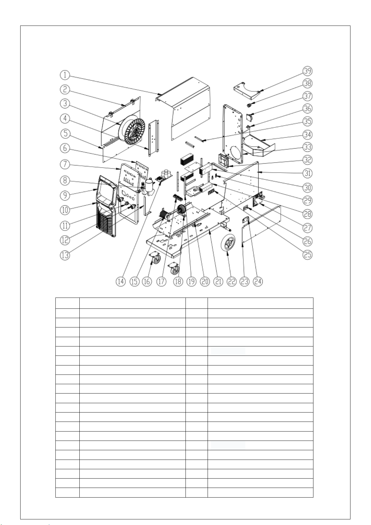
4.3. Welding wire reel installation
4.3.1 Install the wire reel on the holder of wire feeding machine, the hole of wire reel should align with fixed pin on the
holder.
4.3.2 Choose different wire feeding groove according to the wire dimension. (Note: aluminum welding chooses U-shape
groove, other welding wire choose the V-shape groove
4.3.3 Loose the nut of wire pressing roller, thread the welding wire from the spool through the input guide tube, through
the roller groove and into the outlet guide tube. Note: adjust the wire pressing roller and impact the wire, to make sure
the wire will not slide. Avoid the wire deformation due tothe oversize pressure
4.3.4 release the wire by rotating the wire reel anticlockwise. In order to avoid wire loose, the new wire reel will fix the
top of wire on the edge of wire reel. Please cut off this top of wire.
4.3.5 choose different wire feeding groove position according to the wire diameter.
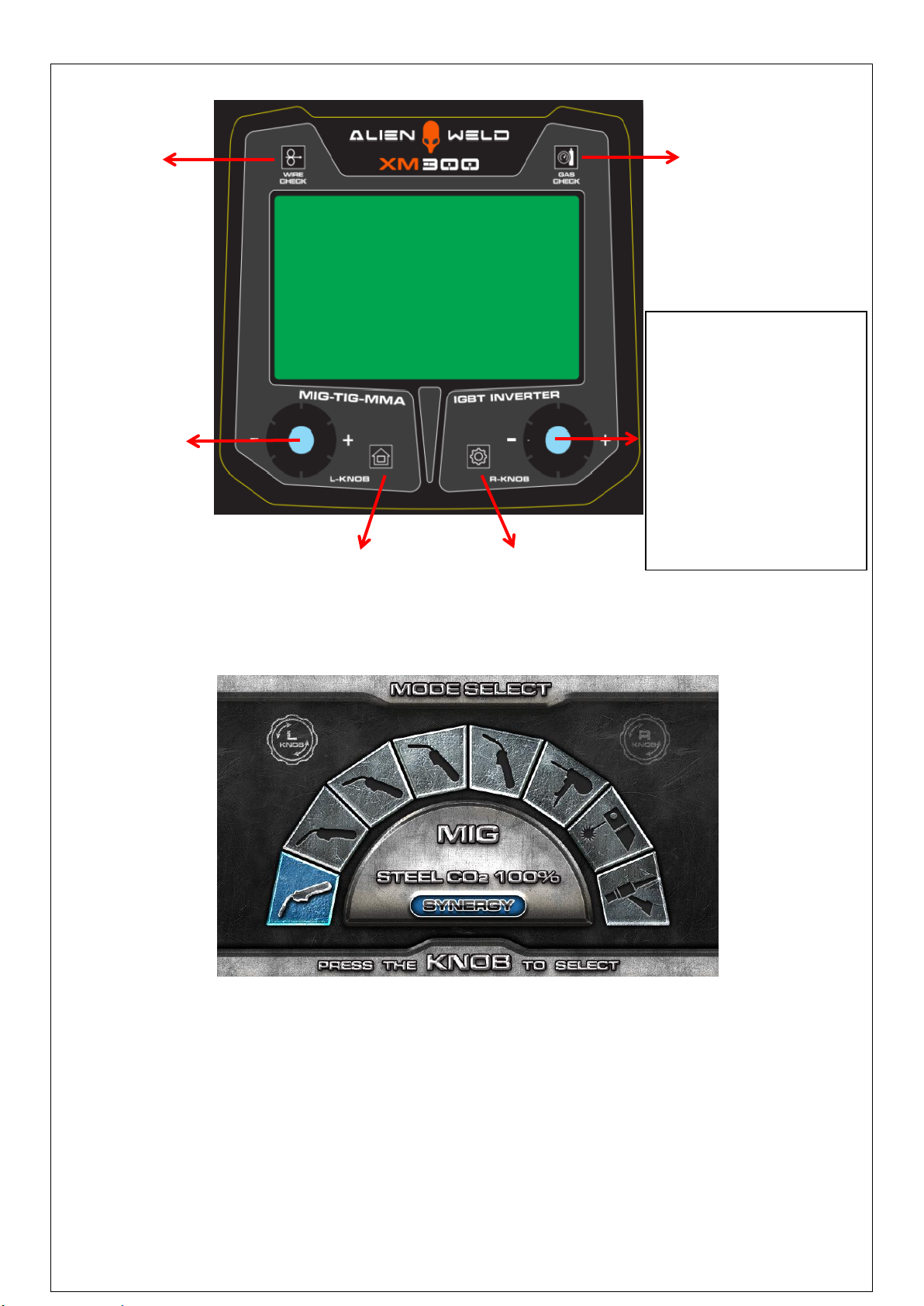
4.3.6 Press “wire check”button to lead out the wire.

7
4.4 Structure instruction
EXPLOSION DRAWING OF POWER SOURCE
NO
Name
NO
Name
1
Machine case
21
Tray
2
Side plate
22
directional wheel
3
Wire spool(optional)
23
Side cover plate II
4
stiffening plate
24
heating plate
5
Side cover plate I
25
rectifier tube
6
Control board
26
EMC board
7
Front metal plate(up)
27
Control board
8
Wire feeding motor
28
Rectifier radiator
9
Front plastic plate(up)
29
IGBT
10
Front plastic plate(down)
30
IGBTradiator
11
Conversion connector
31
clapboard
12
Quick socket
32
Fan
13
Output adapting piece
33
Rear metal plate
14
Power source board
34
Gas bottle tray
15
Output reactor
35
Column fixed
16
Universal wheel
36
Gas bottle hearting socket
17
Rectifier bridge
37
Power switch
18
Main transformer
38
Buckle
19
Column
39
Gas bottle location plate
20
Base plate

8
MODE SELECTION INTERFACE
ROTATE THE KNOB TO SELECT THE MODE, THEN PRESS THE KNOB TO CONFIRM.
WIRE
CHECK
GAS
CHECK
Mode and voltage
regulation
- Function adjustment knob
- Current adjustment
- Inductance adjustment
- Wire diameter adjustment
- 2T/4T adjustment
- Post-flow adjustment
- Slow wire-feeding
adjustment
- Hot start adjustment
- ARC force adjustment
- VRD adjustment
Mode selection interface
Enter button
Function button

9
-MIG Mode
-Inductance adjustment
-Wire diameter
-2T/4T
-Post-flow time
-Slow wire-feeding
-Welding current
-Welding voltage
-MMA Mode
-Welding current adjustment
-Hot start
-ARC force
-VRD

10
-LIFT TIG Mode
-Welding current adjustment
-Alerts: OVER TEMPERATURE!

11
The welding material, process and gas selection are listed below:
Note: Since the arc of MIG welding is much strong than that of MMA welding, please wear welding helmet andprotective clothing.
Material
Process
Gas
Carbon steel
Constant voltage
100% CO2
Carbon steel
Pulse
80/20 mixed gas
Stainless steel
Pulse
98/2 mixed gas
Aluminum silicon
Pulse
100% pure argon
Aluminum magnesium
Pulse
100% pure argon
Aluminum alloy
Cool pulse
100% pure argon
4.5. Gas bottle installation
Connection of Shield Gas
Connect the CO2 hose, which come from the wire feeder to the copper nozzle
of gas bottle. The gas supply system includes the gas bottle, the air regulator
and the gas hose, the heater cable should be inserted into the socket of
machine’s back, and use the hose clamp to tighten it to prevent leaking or
air-in, so that the welding spot is protected.
Please note:
1) Avoid the sunshine on the gas cylinder to eliminate the possible
explosion of gas cylinder due to the increasing pressure of gas
resulted from the heat.
2) Fixed connector avoid leakage of shielding gas affects the
performance of arc welding.
3) It is extremely forbidden to knock at gas cylinder or lay the cylinder
horizontally.
4) Ensure no person is up against the regulator, before the gas release or
shut the gas output.
5) The gas output volume meter should be installed vertically to ensure
the precisely measuring.
6) Before the installation of gas regulator, release and shut the gas for
several time in order to remove the possible dust on the sieve to avail
the gas output.

12
5.OPERATION
5.1 operation
5.1.1 Open the power switch of machine. Open the valve of the gas bottle and adjust the gas flow
5.1.2 According to the wire diameter, select related diameter of MIG torch contact tip, then select corresponding welding
parameter by pressing the “8”button on the control panel, by pressing the “6”button toselect welding mode at the meantime.
5.1.3 According to thickness and process of workpiece, adjust the voltage and the current. Select the “synergy”or “separate”
function by pressing the “8”button on the control panel.
5.1.4 “Inductance adjustment” (1) can change the ARC
5.1.5 Begin to weld by pressing the switch on the MIG torch
5.2 setting the welding current
The selection of welding current, voltage and ARC will influence the stability, welding quality and the productivity during the
welding process. In order to keep a good welding quality, the welding current should match the voltage and the ARC well.
Select the wire diameter according to the globular transfer and the production requirement.
Refer to the below list, choose the common welding current, ARC and voltage.
Range of welding current and voltage in CO2welding
Wireφ(mm)
Short circuit transition
Granular transition
Current(A)
Voltage (V)
Current(A)
Voltage (V)
0.6
40~70
17~19
160~400
25~38
0.8
60~100
18~19
200~500
26~40
1.0
80~120
18~21
200~600
27~40
1.2
100~150
19~23
300~700
28~42
1.6
140~200
20~24
500~800
32~44
5.3-The option of the welding speed
The welding quality and productivity should be taken into consideration for the option of welding speed. In case that the welding
speed increases, it weakens the protection efficiency and speeds up the cooling process. As a consequence, it is not optimal for the
seaming. If the speed is too slow, the work piece will be easily damaged, and the seaming is not ideal. In practical operation, the
welding speed should not exceed 30m/hour.
5.4 he length of wire stretching out
The increase of the length of the solder length, the melting depth, the melting of the wire and the increase of the productivity;
But the dry elongation passes large, the welding wire is easy to fuse, the splash is serious, make the welding process
unsteady. Generally, take the diameter of the wire 10-15 times long.
5.5 The setting of the C02flow volume
The protection efficiency is the primary consideration. Besides, inner-angle welding has better protection efficiency than
external-angel welding. For the main parameter, refer to thefollowing figure.
Option of C02 flow volume
Welding mode
Thin wire C02 welding
Thick wire C02welding
Thick wire, big current
C02welding
C02(L/min)
5~15
15~25
25~50

13
6.WELDING PARAMETERS TABLE
The option of the welding current and welding voltage directly influences the welding stability, welding quality and
productivity. In order to obtain the good welding quality, the welding current and welding voltage should be set optimally.
Generally, the setting of weld condition should be according to the welding diameter and the melting form as well as the
production requirement.
The following parameter is available for reference.
6.1 Parameter for butt-welding (Please refer to the following figure)
Plate thickness
T(mm)
Gap
g(mm)
Wire
φ(mm)
Welding
current (A)
Welding
voltage (V)
Welding speed
(cm/min)
Gas volume
(L/min)
0.8
0
0.8~0.9
60~70
16~16.5
50~60
10
1.0
0
0.8~0.9
75~85
17~17.5
50~60
10~15
1.2
0
1.0
70~80
17~18
45~55
10
1.6
0
1.0
80~100
18~19
45~55
10~15
2.0
0~0.5
1.0
100~110
19~20
40~55
10~15
2.3
0.5~1.0
1.0 or 1.2
110~130
19~20
50~55
10~15
3.2
1.0~1.2
1.0 or 1.2
130~150
19~21
40~50
10~15
4.5
1.2~1.5
1.2
150~170
21~23
40~50
10~15
6.2 Parameter for flat fillet welding (Please refer to the following figure.)
Plate thickness
t(mm)
Corn size
I (mm)
Wire
φ(mm)
Welding
current (A)
Welding
voltage (V)
Welding speed
(cm/min)
Gas volume
(L/min)
1.0
2.5~3.0
0.8~0.9
70~80
17~18
50~60
10~15
1.2
2.5~3.0
1.0
70~100
18~19
50~60
10~15
1.6
2.5~3.0
1.0 ~ 1.2
90~120
18~20
50~60
10~15
2.0
3.0~3.5
1.0 ~ 1.2
100~130
19~20
50~60
10~20
2.3
2.5~3.0
1.0 ~ 1.2
120~140
19~21
50~60
10~20
3.2
3.0~4.0
1.0 ~ 1.2
130~170
19~21
45~55
10~20
4.5
4.0~4.5
1.2
190~230
22~24
45~55
10~20

14
6.3 Parameter for fillet welding in the vertical position (Please refer to the following figure.)
Plate thickness
t(mm)
Corn size
I (mm)
Wire
φ(mm)
Welding current
(A)
Welding
voltage (V)
Welding speed
(cm/min)
Gas volume
(L/min)
1.2
2.5~3.0
1.0
70~100
18~19
50~60
10~15
1.6
2.5~3.0
1.0 ~ 1.2
90~120
18~20
50~60
10~15
2.0
3.0~3.5
1.0 ~ 1.2
100~130
19~20
50~60
10~20
2.3
3.0~3.5
1.0 ~ 1.2
120~140
19~21
50~60
10~20
3.2
3.0~4.0
1.0 ~ 1.2
130~170
22~22
45~55
10~20
4.5
4.0~4.5
1.2
200~250
23~26
45~55
10~20
6.4 Parameter for Lap Welding (Please refer to the following figure.)
Plate thickness
t(mm)
Corn size
I (mm)
Wire
φ(mm)
Welding current
(A)
Welding
voltage (V)
Welding speed
(cm/min)
Gas volume
(L/min)
0.8
A
0.8~0.9
60~70
16~17
40~45
10~15
1.2
A
1.0
80~100
18~19
45~55
10~15
1.6
A
1.0 ~ 1.2
100~120
18~20
45~55
10~15
2.0
A or B
1.0 ~ 1.2
100~130
18~20
45~55
15~20
2.3
B
1.0 ~ 1.2
120~140
19~21
45~50
15~20
3.2
B
1.0 ~ 1.2
130~160
19~22
45~50
15~20
4.5
B
1.2
150~200
21~24
40~45
15~20

15
7.CAUTION
7.1. Working environment
1) Welding should be carried out in arelatively dry environment with its humidity of 90% or less.
2) The temperature of the working environment should be within -10C to 40C.
3) Avoid welding in the open air unless sheltered from sunlight and rain, and never let rainor water infiltrate the machine.
4) Avoid welding in dusty area or environment with corrosive chemical gas.
5) Avoid gas shielded arc welding in environment with strong airflow.
7.2. Safety tips
Over-current/overheating protection circuit is installed in this welding machine. If the output current is too high or overheating
generated inside this welding machine, this welding machine will stop automatically. However, inappropriate use will still lead to
machine damage, so please note:
7.2.1. Ventilation:
High current passes when welding is carried out, thus natural ventilation cannot satisfy the welding machine’s cooling
requirement. Maintain good ventilation of the louvers of this welding machine. The minimum distance between this welding
machine and any other objects in or near the working area should be 30cm. Good ventilation is of critical importance for the
normal performance and service life of this welding machine.
7.2.2. No over-current:
Remember to observe the max load current at any moment (refer to the optioned duty cycle). Make sure that the welding
current should not exceed the max load current.
If welding is carried out under a current which is higher than the max current, over-current protection will occur; the output
voltage of the welding machine will be not stable; arc interruption will occur. In this case, please lower the current.
7.2.3. No over-load:
Over-load current could obviously shorten the welding equipment’s life, or even damage the machine.
A sudden halt may occur while the welding operation is carried out while this welding machine is of over-load status. Under
this circumstance, it is unnecessary to restart this welding machine. Keep the built-in fan working to bring down the
temperature inside the welding machine.
7.2.4. Avoid electric shock:
An earth terminal is available for this welding equipment. Connect it with the earth cable to avoid the static and electric
shock.

16
8.MAINTENANCE
1. Disconnect input plug or power before maintenance or repair on
machine.
2. Be sure input ground wire is properly connected to a ground
terminal.
3. Check whether the inner gas-electricity connection is well (esp. the
plugs) and tighten the loose connection; if there is oxidization,
remove it with sandpaper and then re-connect.
4. Keep hands, hair, loose clothing, and tools away from electrical
parts such as fans, wires when the machine is switched on.
5. Clear the dust at regular intervals with clean and dry compressed
air; if the working condition is with heavy smoke and air pollution,
the welding machine should be cleaned daily.
6. The compressed air should be reduced to the required pressure lest
the little parts in the welding machine be damaged.
7. To avoid water and rain, if there is, dry it in time, and check the
insulation with mega-meter (including that between the connection
and that between the case and the connection). Only when there is
no abnormal phenomenon should the welding continue.
8. If the machine is not used for a long time, put it into the original
packing in dry condition.

17
9.DAILY CHECKING
To make best use of the machine, daily checking is very important. During the daily checking, please check in the order of torch,
wire-feeding vehicle, all kinds of PCB, the gas hole, and so on. Remove the dust or replace some parts if necessary. To maintain the
purity of the machine, please use original welding parts.
Cautions:Only the qualified technicians are authorized to undertake the repair and check task of this welding equipment in case of
machine fault.
9.1. Power supply
Part
Check
Remarks
Control panel
1. Operation, replacement and installation of Switch
2. Switch on the power, and check if the power indicator is on.
Fan
1. Check if the fan is functioning and the sound generated is normal.
If the fan doesn’t work or the
sound is abnormal, do inner
check.
Power supply
1. Switch on the power supply, and check if abnormal vibration,
heating of the case of this equipment, variation of colors of case
or buzz presents.
Other parts
1. Check if gas connection is available, case and other joints are in
good connection.
9.2. Welding torch
Part
Check
Remarks
Nozzle
1. Check if the nozzle is fixed firmly and
distortion of the tip exists.
Possible gas leakage occurs due to the unfixed nozzle.
2. Check if there is spatter sticking on the
nozzle.
Spatter possibly leads to the damage of torch. Use
anti-spatter to eliminate the spatter.
Contact tip
1. Check if the contact tip is fixed firmly.
Unfixed contract tip possibly leads to unstable arc.
2. Check if the contact tip is physically
complete.
The physically incomplete contact tip possibly leads to
unstable arc and arc automatically terminating.
Wire feeding
hose
1. Make sure that there is the agreement of
wire and wire feed tube.
Disagreement of the diameters of wire and wire feed tube
possibly leads to the unstable arc. Replace it/them if
necessary.
2. Make sure that there is no bending or
elongation of wire feed tube.
Bending and elongation of wire feed tube possibly leads to
the unstable wire feed and arc. Replace it if necessary.
3. Make sure that there is no dust or spatter
accumulated inside the wire feed tube,
which makes the wire feed tub blocked.
If there is dust or spatter, remove it.
4. Check if the wire feed tube and O-shaped
seal ring are physically complete.
The Physically incomplete wire feed tube or O-shaped seal
ring possibly leads to the excessive spatter. Replace the wire
feed tube or O-shaped seal ring if necessary.
Diffuser
1. Make sure that the diffuser of required
specification is installed and is unblocked.
Defection weld or even the damage of torch occurs due to the
non-installation of diffuser or the unqualified diffuser.

18
9.3. Wire feeder
Part
Check
Remarks
Pressure
adjusting
handle
1. Check if the pressure-adjusting handle is fixed
and adjusted to the desired position.
The unfixed pressure-adjusting handle leads to
the unstable welding output.
Wire-feeding
hose
1. Check if there is dust or spatter inside the hose
or beside wire-feeding wheel.
Remove the dust.
2. Check if there is a diameter agreement of wire
and wire-feeding hose.
Non-agreement of the diameter of wire and
wire-feeding hose possibly leads to the excessive
spatter and unstable arc.
3. Check if rod and wire feeding groove are
concentric.
Unstable arc possibly occurs.
Wire-feeding
wheel
1. Check if there is an agreement of wire diameter
and wire-feeding wheel.
Non-agreement of wire diameter and
wire-feeding wheel possibly leads to the
excessive spatter and unstable arc.
2. Check if the wire groove is blocked.
Replace it if necessary.
Pressure
adjusting
wheel
1. Check if the pressure adjusting wheel can
rotate smoothly, and it’s physically complete.
Unstable rotation or physically incompleteness of
the wheel possibly leads to unstable wire feeding
and arc.
9.4.Cables
Part
Check
Remarks
Torch
cable
1. Check if the cable of torch is twisted.
The twisted torch cable leads to unstable wire
feeding and arc.
2. Check if the coupling plug is in loose connection.
Output
cable
1. Check if the cable is physically complete.
Relevant measures should be taken to obtain
stable weld and prevent the possible electric
shock.
2. Check if insulation damage or loose connection
exists.
Input
cable
1. Check if the cable is physically complete.
2. Check if insulation damage or loose connection
exists.
Earth
cable
1. Check if the earth cables are well fixed and not
short-circuited.
Relevant measures should be taken to prevent the
possible electric shock.
2. Check if this welding equipment is well grounded.
This manual suits for next models
2
Table of contents
Other ALIEN WELD Welding System manuals