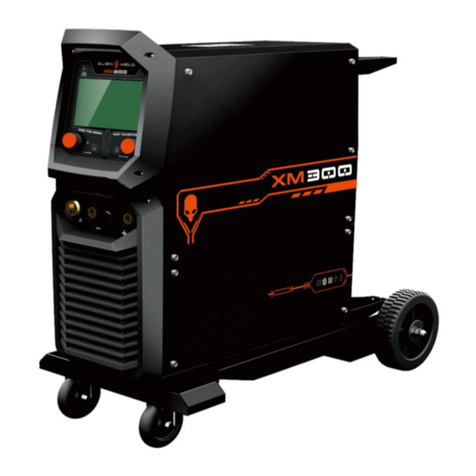
ALIEN WELD XT200 User manual

1
MODEL: xt200
TIG HIGH FREQUENCY / MMA
OPERATORS’ MANUAL
IMPORTANT: Welcome to use the Alienweld XT200 welding machine. Read This Owner'sManual carefully before
attempting to use this equipment. Used correctly, can prolong the service life of the arc welding machine!

CONTENT
1. SAFETY ....................................................................................................................................................................................... 1
1.1 SIGNAL EXPLANATION...................................................................................................................................................................... 1
1.2 ARC WELDING DAMAGE............................................................................................................................................................... 1
1.3 INSTALLATION, OPERATION AND MAINTANCE NOTICES.............................................................................................. 4
1.4 THE KNOWLEDGE OF ELECTRIC AND MAGNETIC FIELDS ...................................................................................................... 5
2. ARC WELDING MACHINE INTRODUCTION..........................................................................................................................6
2.1 DEVICE BRIEF INTRODUCTION........................................................................................................................................................6
2.2 WORKING PRINCIPLE.......................................................................................................................................................................7
2.3 VOLT-AMPERE CHARACTERISTIC................................................................................................................................................7
3. INSTALLATION AND ADJUSTMENT..................................................................................................................................... 8
3.1 PARAMETERS .................................................................................................................................................................................... 8
3.2 DUTY CYCLE & OVER HEAT............................................................................................................................................................10
3.3 EQUIPMENT CONNECTION(TIG/MMA).................................................................................................................................11
4. OPERATION INTRODUCTION................................................................................................................................................13
4.1 LAYOUT FOR THE FRONT PANEL..............................................................................................¡Error! Marcador no definido.
4.2 WELDING PARAMETERS...............................................................................................................................................................15
4.3 OPERATION ENVIRONMENT...........................................................................................................................................................................................17
4.4 WELDING NOTICES.........................................................................................................................................................................18
5. ELECTRICAL PRINCIPLE DRAWING.......................................................................19
6. EXPLOSIVE VIEW.....................................................................................................20

1
1. SAFETY
1.1 Signal Explanation
The above signals mean warning! Notice! Running parts and getting an electric shock or thermal parts will take
damage for your body or others. The corresponding notices are as follows. It is quite a safe operation after taking
several necessary protection measures.
1.2 Arc Welding Damage
⚫The following signals and word explanations are to some damages for your body or others happening on the
welding operation. While seeing these, please remind of yourself or others to be dangerous.
⚫Only ones who are trained professionally can install, debug, operate, maintain and repair the equipment.
⚫During the operation, non-concerned people should be lift, especially for children.
⚫After shutting off the machine power, please maintain and examine the equipment according to because of the DC
voltage existing in the electrolytic capacitors.
ELECTRIC SHOCK CAN KILL!
⚫Never touch electrical parts.
⚫Wear dry, hole-free glovesand clothesto insulate you.
⚫Insulate yourself from workpiece and ground using dry insulation. Make certain the insulation is large enough to
cover your full area of physical contact with workpiece and ground.
⚫Take carefully when using the equipment in small place, falling-off and wet circumstance.
⚫Never shut off the machine power before installation and adjustment.
⚫Ensure to install the equipment correctly and ground the work or metal to be welded to a good electrical (earth)
ground according to the operation manual.
⚫Always confirm that whether the earth wire of equipment case is access to the power control box through the
earth wire of power cable before shutting off the power switch.
⚫Check whether the input cable is damaged or exposed, replace the damaged cable immediately.
⚫Shut off the power when you’re not using the equipment.

2
⚫Don't use the dilapidated, damaged, small sized and bad contact cables.
⚫Don't twine the cableson your body.
⚫If you touch one electrode of the workpiece、ground or equipment, please don’t touch the another electrode.
⚫Keep the equipment in good condition, timely maintain or replace the damaged parts, make regular
maintenance according to the instructions.
⚫If the equipment operates deviate from the ground, please take safety measures.
⚫When the clamp is not used in connection with welding workpiece, proceeding insulation, in order to avoid
contacting with the metal objects.
⚫Don’t connect two or more electrodes or output cables froma single output end of the welding machine.
WELDING SPARKS CAN CAUSE FIRE OR EXPLOSION!
⚫Protect yourself and others, avoid from the sparksand hot metal damage.
⚫Don't welding in the area of combustible materials; the splash spark may cause burning.
⚫Remove the combustible materials within 10 m around the welding arc. If not, use the approved mulch covers
them closely.
⚫Beware of welding sparks and fever material caused by welding, they are easy to fly to neighboring areas
through small sew narrow opening.
⚫Alert to fire, put a fire extinguisher nearby the welding area.
⚫When welding on the ceiling, floor, wallsor isolation thing, alert to cause fire.
⚫Don't weld on the airtight container such as oil tank, the cylinder or pipe, unless take the feasible measures
before.
⚫According to the actual situation, connect the cables to the workpiece as close as possible to the welding area,
in order to avoid the welding current through too long or unknown path, then cause shock and fire.
⚫Don't use arc welding machine for pipeline thaw out.
⚫If you do not use the equipment l, please take down the electrode from the electrode holder or pulled out the
welding cablesform the output end.
⚫Wear no oil protective clothing, such as leather gloves, thick welding clothes, no flanging pants, boots, hats, etc.
⚫Before welding, the present person should hand over all the fuels, such as butane lighter and matches.
FUMES AND GASES CAN BE DANGEROUS!

3
⚫Let your head away from dust, do not inhale the dust.
⚫If indoors, keep good ventilation, or use exhaust device to drive the smoke and gas that produced by welding.
⚫Read relevant safety data material, follow the manufacturer’s introduction and suggestions for metals,
consumables, cloth, clean goods, etc.
⚫When process welding in a narrow area, ensure good ventilation or wear supplied-air respirator, at the
meanwhile, there must have trained person present. The dust and gas produced by welding will reduce the
oxygen content, and cause effect and damage to people's health.
⚫Don't process welding around the field that have skimmed, cleaning or injection work, the heat and radiation
produced by arc reacts with the water vapor in the air may produce the gas with strong toxicity and
stimulating.
⚫Don't process welding on the material surface of electroplating metal, unless the coating has been removed,
welding area is in good ventilation. Wear supplied-air respirator if necessary. Because in welding, the coated
metal will release poisonous gas.
THERMAL COMPONENTS MAY CAUSE SEVERE BURNS!
⚫Don’t touch the thermal components directly by hand.
⚫Use the welding gun or torch to welding after cooling.
ARC RAYS CAN DAMAGE YOUR EYS AND BURN YOUR SKIN!
⚫During welding and watching, wear a helmet with the proper filter and cover plates to protect your face and
eyes from sparks.
⚫Use the glasses with side armor and approved safety glasses under the helmet.
⚫Protect other nearby personnel with suitable, non-flammable screening and /or warn them not to watch the arc
nor expose themselvesto the arc raysor to hot spatter or metal.
⚫Use suitable clothing and spats made from durable flame-resistant material (fur and wool) to protect your skin.

4
1.3 Installation, operation and maintenance notices
FIRE OR EXPLOSION MAY CAUSE DANGEROUS!
⚫Don’t place and install the equipment in the fuel and flammable surface or nearby.
⚫Don't make the power cord overload, ensure that the specifications of power supply system, load rate are not
exceeding the rated value, and operating equipment correctly.
EQUIPMENT SLIPPED OFF MAY CAUSE DANGEROUS!
⚫Through crane hoisting equipment, prohibit to rolling cylinders or other components.
⚫It must have enough carrying of equipment to hoist or support welding equipment.
⚫If using a forklift to hoist the equipment, it must be ensured that the forklift arm is long enough to extend to the
other side of the equipment.
RUNNING PARTS MAY BE DANGEROUS!
⚫Away from the running components, such as the fan, etc.
⚫Far from the equipment extrusion parts, such as the drive wheels, etc.
⚫Ensure that all the clutch window, panel, cover board or protective device of the equipment in a safe place
⚫The protection class of our arc welding machine is IP23S,not suitable for operating in heavy rain.
⚫Excessive noise isharmful to your listening. In the welding process, it can cause noise, if the noise decibels istoo
high, please wear hearing protector.

5
1.4 The knowledge of electric and magnetic fields
Electric current flowing through any conductor causes localized Electric and Magnetic Fields (EMF). The
discussion on the effect of EMF is ongoing all the world. Up to now, no material evidences show that EMF may have
effects on health. However, the research on damage of EMF is still ongoing. Before any conclusion, we should minimize
exposure to EMF as few as possible.
In order to minimize EMF, we should use the following procedures:
Tie the cables together through woven.
All cables should be put away and far from the operator.
Never coil the power cable around your body.
Make sure welding machine and power cable to be far away from the operator as far as possible according to
the actual circumstance.
Connect the work cable to the workpiece asclose as possible to the area being welded.
The people with heart-pacemaker shouldbe away from the welding area.

6
2. ARC WELDING MACHINE INTRODUCTION
This operation manual is suitable for the inverter DC pulsed (non-pulsed) TIG/MMA machine.
2.1 Brief introduction
This series welding machine adopts the latest pulse width modulation (PWM) technology and insulated gate
bipolar transistor (IGBT) inverter technology, which can realize TIG operation and change work frequency to
medium frequency so as to replace the traditional hulking work frequency transformer with the cabinet medium
frequency transformer. Thus, it is characterized with portable, small size, light weight, low consumption and etc.
This series machine hassuch good performance: in TIG mode, Pre flow time(3)start current(4)current up slope
(5)welding current(6)base current(7)pulse frequency(8)Pulse duty factor(12)Down slope time(9)
Crater current(10)post flow time(11)and etc parameters can be adjusted; In MMA mode, arc starting current(14)
arc force(15)and the welding current parameters also can be adjusted separately, the welding mode can select by
“welding mode selective switch”(2)the welding parameters can adjust by ”selection knob”(1).
When adjust the” selection knob” to the corresponding function, the pilot light on, then press the “selection knob”
to confirm, the pilot light is twinkling. Press the “selection knob” again, the output pulsed conditions transform by “ON”
or “OFF”. Pulse selective pilot light is(13),This series machine have intelligence protection function inside, such as
over-voltage、low-voltage、over-current、low-current. When the machine arise the failures above, the alarm pilot
light in the front panel (17)will light,in the meantime, it will cut the output current, play the role of self-protection
and prolong the service life. Both MMA and TIG mode can achieve excellent welding effect.
This series welding machine is suitable for all positions welding for various plates made of stainless steel,
carbon steel, alloyed steel, titanium, etc, which is also applied to pipe installment, mould mend, petrochemical,
architecture decoration, car repair, bicycle, handicraft and common manufacture.
The Welder Characteristics:
IGBT——Insulation Gate Bipolar Transistor;
MMA——Manual Metal Arc welding;
TIG——Tungsten Inert Gas welding;

7
2.2 Working Principle
The working principle of THIS- series welding machines is shown as the following figure. Single phase work
frequency AC 220V or 230V (50 Hz) is rectified into DC (about 300V), then is converted to medium frequency AC (about
40-60KHz) by inverter device (IGBT), after reducing voltage by medium transformer (the main transformer) and
rectifying by medium frequency rectifier (fast recovery diode), and is outputted by inductance filtering. The circuit
adopts current feedback control technology to insure current output stably. Meanwhile, the welding current
parameter can be adjusted continuously and steplessly to meet with the requirements of welding craft.
2.3 Volt-Ampere Characteristic
This series welding machine hasan excellent volt-ampere characteristic, whose graph is shown as
the following figure. The relation between the conventional rated loading voltageU2 the conventional welding
current I2 is as follows:
When I2≤600A,U2=10+0.04 I2(V);When I2>600A,U2=34(V).
63
34
10
0600 I2(A)
U2(V)
Working
point
Volt-ampere characteristic The relation between the
conventional loading
voltage and welding current

8
3. INSTALLATION AND ADJUSTMENT
3.1 Parameters
Type
Parameter
160
180
200
250
Input voltage
1 phase,220~230V±10%,50/60Hz
Rated input current(A)
TIG
MMA
TIG
MMA
TIG
MMA
TIG
MMA
16.4
26.4
21
33.5
26
40.6
28
43
Rated input power(KW)
2.9
4.7
3.7
5.9
4.6
7.2
4.9
7.5
Power factor
0.80
Maximum no-load voltage (V)
62~64
62~64
Welding current range(A)
5~160
5~180
5~200
5~220
Efficiency
≥80%
Duty cycle(40℃,10 min)
160A 40%
180A 30%
200A 25%
220A 25%
100A 100%
Protection class
IP21
Insulation class
F
Dimensions
(L x W x H)(mm)
380X120X220
Weight(Kg)
5.5
6.2

9
Type
Parameter
160
200/250
Input voltage
1 phase,
110V±10%,
50/60Hz
1 phase,
220V±10%,
50/60Hz
1 phase,110V±10%,
50/60Hz
1 phase,220V±10%,
50/60Hz
Rated input current(A)
TIG
MMA
TIG
MMA
TIG
MMA
TIG
MMA
35
45
21
33.5
35
45
25/28
42/48
Rated input power(KWA)
3.9
4.9
4.6
7.2
3.9
4.9
5.5/6.2
9.2/10.5
Power factor
0.80
Maximum no-load voltage (V)
62~64
62~64
Welding current range(A)
5-145
5-160
5-145
5-200/220
Efficiency
≥80%
Duty cycle(40℃,10 min)
145A 100%
160A 40%
145A 100%
200/220A 25%
145A 100%
145A 100%
Protection class
IP21
Insulation class
F
Dimensions
(L x W x H)(mm)
380X120X220
Weight(Kg)
5.5
6.2

10
3.2 Duty cycle and overheat
Duty cycle,also called load duration rate,
use “X” stands for. It’s defined as the
proportion of the time that a machine can
work continuously within a certain time (10
minutes). The rated duty cycle means the
proportion of the time that a machine can
work continuously within 10 minutes when it
outputs the rated welding current.
The relation between the output welding
current” I” and the duty cycle “X”, is shown as the right figure.
If the welder is over-heat, the thermal relay inside will break and input a command signal to circuit board to cut
output welding current and brighten the alarm pilot light. At This time, the machine should be relaxed for 15 minutes
to cool the fan. When operating the machine again, the welding output current or the duty cycle should be reduced.
I(A)
0
100%
25%
XThe relation between TIG 200A welding
current and duty cycle
200100

11
3.3 Equipment Connection
(TIG)
⚫Workpiece is connected to the output positive electrode of welding machine, and welding torch is connected to
the negative electrode, which is called DC POSITIVE CONNECTION; otherwise, that is called DC NEGATIVE
CONNECTION. Generally, it is usually operatedin DC POSITIVE CONNECTION in TIG welding mode.
⚫This arc welding machine is operating with high frequency arc start or LIFT arc starting, when operates in the
nearby to high frequency sensitive equipment, please take LIFT arc starting way.
TIG TORCH CONNECTOR
TIG TORCH SWITCH
CONNECTOR
GAS OUTLET
CONNECTOR
EARTH CLAMP
CONNECTOR
POWER CABLE
POWER SWITCH
GAS OUTLET
CONNECTOR

12
(MMA)
⚫Workpiece is connected to the output negative electrode of welding machine, and welding torch is connected to
the positive electrode, which is called DC NEGATIVE CONNECTION; otherwise, that is called DC POSITIVE
CONNECTION. Generally, it is usually operated in DC NEGATIVE CONNECTION in TIG welding mode.
ELECTRODE
HOLDER
EARTH CLAMP
ELECTRODE
HOLDER
EARTH CLAMP
NEGATIVE CONNECTION
POSITIVE CONNECTION

13
4. OPERATION INTRODUCTION
4.1 Layout for the front panel
1 2 3 4 5 6 7 8 9 10 11 12 13 14 15 16
17 18 19 20 21 22 23
1. Pre flow time 0-1 S
2. Pulse
3. Start current 5-200 A
4. Up slope time 0-5 S
5. Welding current 5-200 A
6. Pulse duty factor 5-100 % (Only pulse machine hasThis function)
7. Pulse frequency 0.5-100 HZ (Only pulse machine hasThis function)
8. Base current 5-200 A (Only pulse machine has This function)
9. Down slope time 0-5 S
10. Arc starting current 1-10
11. Arc force 1-10

14
12. Crater current 5-200 A
13. Post flow time 0.1-10 S
14. Pulse duty factor light % (Only pulse machine has This function)
15. Time unit
16. Frequency unit
17. High frequency TIG
18. LIFT TIG
19. MMA
20. 2T
21. 4T
22. VRD
23. Adjusting knob

15
4.2 Welding Parameters
4.2.1 Joint forms in TIG/MMA
a butt joint b comer joint c lap joint d T joint
4.2.2 The explanation of welding quality
The relation of welding area color & protect effect of stainless steel
Welding area
color
Argent ,
golden
Blue
Red-grey
Grey
Black
Protect effect
Best
Good
Better
Bad
Worst
The relation of welding area color & protect effect of Ti-alloy
Welding area
color
Bright argent
Orange-yellow
Blue-purple
Caesious
white powder of
titanium oxide
Protect effect
Best
Good
Better
Bad
Worst
4.2.3 TIG Parameters Matching
The corresponding relationship between gas nozzle diameter and electrode diameter
Gas nozzle diameter /mm
Electrode diameter /mm
6.4
0.5
8
1.0
9.5
1.6 or 2.4
11.1
3.2
a 对接接头 b 角接接头 c 搭接接头 d T形接头

16
The selective range of Gas nozzle diameter and protective gas flow rate
Welding current
range/A
DC Positive Connection
Alternating Current
Gas nozzle diameter
/mm
Gas flow rate /L·min-1
Gas nozzle diameter
/mm
Gas flow rate /L·min-1
10~100
4~9.5
4~5
8~9.5
6~8
101~150
4~9.5
4~7
9.5~11
7~10
151~200
6~13
6~8
11~13
7~10
201~300
8~13
8~9
13~16
8~15
Tungsten electrode shape and the welding current range (DCEP)
Tungsten electrode
diameter /mm
sharpened of the
electrode diameter
/mm
angle of cone(°)
Background
current/A
Pulse current
1.0
0.125
12
2~15
2~25
1.0
0.25
20
5~30
5~60
1.6
0.5
25
8~50
8~100
1.6
0.8
30
10~70
10~140
2.4
0.8
35
12~90
12~180
2.4
1.1
45
15~150
15~250
3.2
1.1
60
20~200
20~300
TIG of stainless steel (single run welding)
Workpiece
thickness
/mm
Joint form
Tungsten
electrode
diameter/mm
Welding wire
diameter/mm
Argon gas
flow rate/
L·min-1
Welding
current
(DCEP)
Welding
speed
/ cm·min-1
0.8
Butt joint
1.0
1.6
5
20~50
66
1.0
Butt joint
1.6
1.6
5
50~80
56
1.5
Butt joint
1.6
1.6
7
65~105
30
1.5
Corner joint
1.6
1.6
7
75~125
25
2.4
Butt joint
1.6
2.4
7
85~125
30
2.4
Corner joint
1.6
2.4
7
95~135
25
3.2
Butt joint
1.6
2.4
7
100~135
30
3.2
Corner joint
1.6
2.4
7
115~145
25
4.8
Butt joint
2.4
3.2
8
150~225
25
4.8
Corner joint
3.2
3.2
9
175~250
20

17
4.3 Operation Environment
⚫Height above sea level is below 1000m.
⚫Operation temperature range -10℃~+40℃.
⚫Relative humidity is below 90 %(20℃).
⚫Preferably site the machine some angles above the floor level, the maximum angle does not exceed 15°.
⚫Protect the machine against heavy rain or in hot circumstance against direct sunshine.
⚫The content of dust, acid, corrosive gas in the surrounding air or substance can not exceed normal
standard.
⚫Take care that there is sufficient ventilation during welding. There is at least 30cm free distance between
the machine and wall.
Parameters of piping back sealing welding for mild steel(DCEP)
Piping
diameter/m
m
Tungsten
electrode
diameter/mm
Gas nozzle
diameter
/mm
Welding wire
diameter/mm
Welding
current/A
Arc
voltage/V
Argon
flow
rate
/L·min-1
Welding
speed
/cm·min-1
38
2.0
8
2
75~90
11~13
6~8
4~5
42
2.0
8
2
75~95
11~13
6~8
4~5
60
2.0
8
2
75~100
11~13
7~9
4~5
76
2.5
8~10
2.5
80~105
14~16
8~10
4~5
108
2.5
8~10
2.5
90~110
14~16
9~11
5~6
133
2.5
8~10
2.5
90~115
14~16
10~12
5~6
159
2.5
8~10
2.5
95~120
14~16
11~13
5~6
219
2.5
8~10
2.5
100~120
14~16
12~14
5~6
273
2.5
8~10
2.5
110~125
14~16
12~14
5~6
325
2.5
8~10
2.5
120~140
14~16
12~14
5~6

18
4.4 Operation Notices
⚫Read §1 carefully before attempting to use thisequipment.
⚫Connect the ground wire with the machine directly.
⚫The input power should be single phrase、50-60Hz、220-230V alternating current(AC).
⚫In case closing the power switch, no-load voltage may be exported. Do not touch the output electrode with
any part of your body.
⚫Before operation, no concerned people should be left. Do not watch the arc in unprotected eyes.
⚫Ensure good ventilation of the machine for arc welding heat dissipation and improve duty ratio.
⚫Turn off the engine when the operation finished economizing energy source.
⚫When power switch shuts off protectively because of failure. Don resolved. Otherwise, the range of
problem will be extended.
⚫If there is any problem and has no the authorized professional maintenance personal of our company,
please contact local our company agent or the branch company!
Table of contents
Other ALIEN WELD Welding System manuals
Popular Welding System manuals by other brands

Kemppi
Kemppi Minarc 150 Service manual

BorMann
BorMann PRO BGB2035 user manual

ESAB
ESAB 350mpi instruction manual

Migatronic
Migatronic AUTOMIG 223i/273i instruction manual

BINZEL-ABICOR
BINZEL-ABICOR ABIPLAS WELD 100 POWDER W operating instructions

Linde
Linde BOC Smootharc Advance MIG 255R operating manual