Quick Reference Guide QRG-02
4S-03
RESET
RESET
Error Message Reason Solution
Too Long Fiber
•
The fiber end-face is placed on the electrode
centerline, or beyond it
•
The cleave length (bare fiber part) is too long
•
Dust or dirt is on the objective lens
Press , and set the fiber end-face between the
electrode centerline and the V-groove edge.
Confirm the placement of the stripped fiber end on the fiber
cleaver. Check the cleave length.
Execute [Dust Check]. Clean the lens when dust or dirt exists.
Too Dusty Fiber
•
Dust or dirt is on the fiber surface
•
Dust or dirt is on the objective lens.
•
[Cleaning Fuse] time is too short or “OFF”.
•
Splicing fibers with unresolvable core positions using
the SM or DS modes
•
[Align] is set to “Core” when splicing fibers with unresolvable
core positions when using other splice modes
•
[Focus] is incorrectly set when using other
splice modes.
Completely prepare the fiber again (strip, clean and cleave).
Execute the [Dust Check]. Clean the lens if dust or dirt exists.
Set the [Cleaning Fuse] time to “150ms.” When splicing carbon
coated fibers, set to “200ms.”
Use the MM mode to splice fibers with unresolvable core
positions (i.e. MM fiber).
Set [Align] to “Clad” to splice these fibers (i.e. MM fiber).
Set [Focus] to “Edge” to splice fibers with unresolvable core
positions (i.e. MM fiber). To splice distinct core fibers, “Auto”
or the correct focus value should be entered.
ZL/ZR Motor
Overrun
•
The fiber is set too far back and does not reach
the splice point
•
The cleave length (bare fiber part) is too short.
•
Splicing loose buffer tube fiber without protrusion engaged
Press , re-position the fiber again with the end-face
closer to the electrodes.
Confirm the placement of the stripped fiber end on the fiber
cleaver. Check the cleave length.
Flip the protrusion switch so it engages the loose buffer tube fiber.
Large Cleave
Angle
•
Bad fiber end-face
•
[Cleave Limit] was changed to a low cleave angle.
Check the condition of the fiber cleaver. If the blade is worn,
rotate the blade to a new position.
Load the default cleave angle value from the splice mode database.
Cleave
Shape NG
•
Bad fiber end-face Clean and check the condition of the fiber cleaver.
If the blade is worn, rotate the blade to a new position.
High Estimated
Loss
•
Dust or dirt is on the fiber surface
•
Bad fiber end-face
•
Improper splice mode selected
•
•
•
•
•
•
•
•
•
•
•
•
•
•
•
•
•
•
•
•
Unstable fusing discharge
Completely prepare the fiber again (strip, clean and cleave).
*This table only shows a few possible errors. Refer to the instruction manual for a more comprehensive list.
Check the condition of the fiber cleaver. If the blade is worn,
rotate the blade to a new position.
Select proper splice mode
Electrodes might be worn. Perform [Electrode Stabilization] or
replace electrodes.
Fujikura Ltd.
1-5-1, Kiba, Koto-ku, Tokyo 135-8512, Japan
General inquiries : +81-3-5606-1164
Service & support : +81-3-5606-1534
Fujikura Asia Ltd. 438A Alexandra Road,Block A Alexandra Technopark #08-03, Singapore 119967
General inquiries, service & support : +65-6-278-8955 https://www.fujikura.com.sg
Fujikura Europe Ltd.
C51 Barwell Business Park, Leatherhead Road, Chessington, Surrey, KT9 2NY, UK
General inquiries : +44-20-8240-2000
Service & support : +44-20-8240-2020 https://www.fujikura.co.uk
AFL
260, Parkway East, Duncan, SC29334, USA
General inquiries : +1-800-235-3423
Service & support : +1-800-866-3602 https://www.aglobal.com
Fujikura (CHINA) Co., Ltd 7thFloor, Shanghai Hang Seng Bank Tower, 1000 Lujiazui Ring Road, Pudong New Area, Shanghai 200120, CHINA
General inquiries, service & support : +86-21-6841-3636 http://www.fujikura.com.cn
Authorized Splicer Distributor
Contact Addresses
Solutions for Common Splicer Errors
https://www.fujikura.com
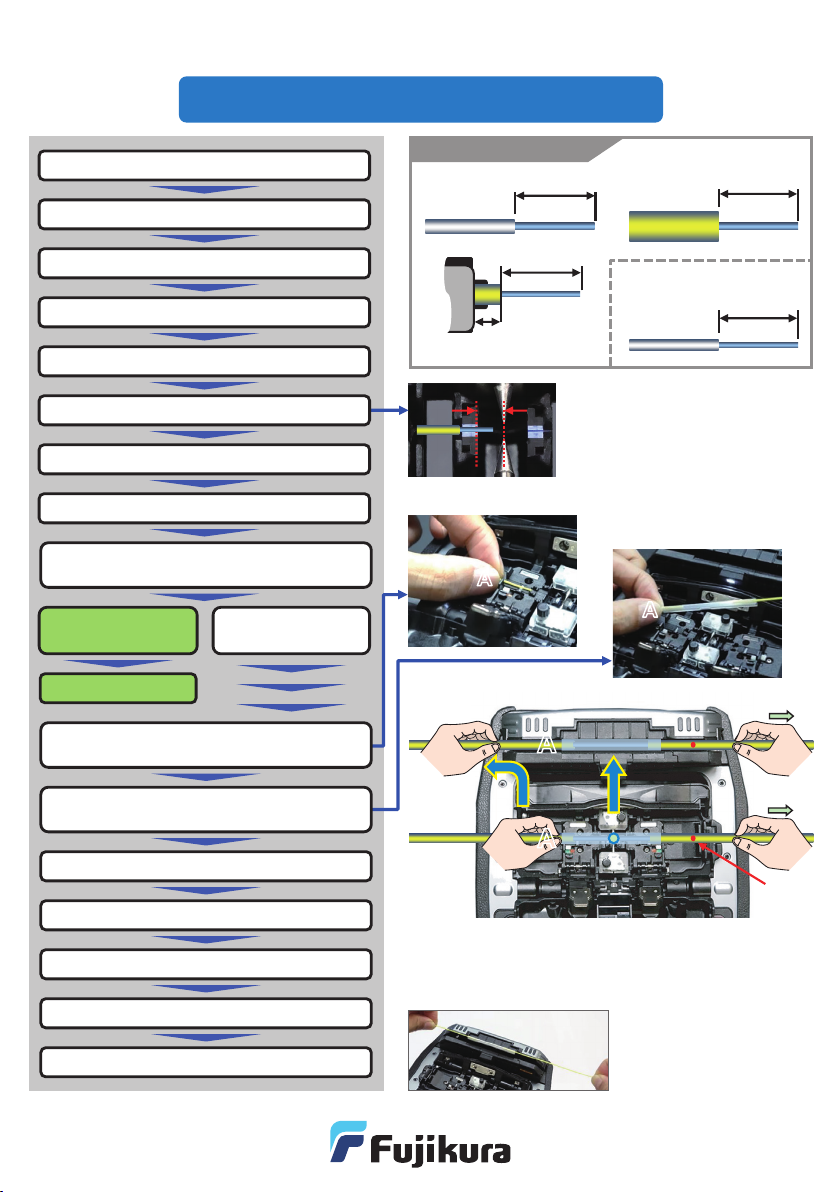
Quick Reference Guide QRG-02
S-03 1
LED
Tools for Splicing Operation
Fusion Splicer
Core Alignment
Consumables for
cleaning
•Cotton
•Cotton swab
•Alcohol
Single Fiber
Stripper
Optical Fiber
Cleaver Protection sleeve
The following items are standard tools for optical fiber splicing.
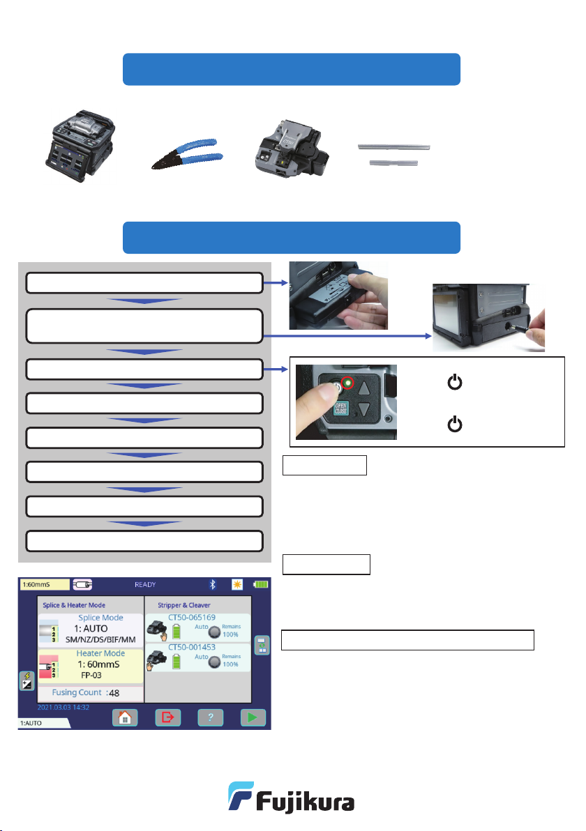
Setup & Preparation Before Splicing
Turning ON
Press key until green LED
turns on.
Turning OFF
Press
turns on.
Install battery pack or DC adaptor
Plug AC adaptor into the DC adaptor.
*No need when using battery pack.
Turn splicer ON.
Confirm Heater Mode
Check Wireless Communication status
Clean before splicing
Setup & Preparation completed
Confirm Splice Mode
•Select “G652/SM AUTO” to splice standard SM
•Select “AUTO” mode to splice unknown fiber types.
However, splice time might be longer.
•“G652/SM FAST” will shorten the splice time. However,
periodic Fusing Power Calibrations are neccesary.
•Select the adequate heater mode according to the sleeve.
The [READY] screen shows the current heater mode.
•When using a protection sleeve which is not made by Fujikura,
please set parameters based on the specific sleeve.
•Splicr can connect to the CT50 cleaver and RS02/03 ribbon
stripper.
•When wireless comunication is established, the splicer
monitors the conditon of these tools. If the splicer sees that the
tool has an issue, it alerts the operator with an on-screen alarm.
•After initial pairing, the devices are always paired.
Communication between splicer, cleaver and stripper resumes
automatically even after power cycling.
•Refer to the setting guide “SG-02” or instruction manual for
wireless communication function details.
Basic operations can be performed from the
touch screen after the power is turned on.
*
Splice Mode
Heater Mode
Wireless communication with accessories
key until red LED
fibers (ITU-T G.652).