DR-235TMkIIT
Service
Manual
CONTENTS
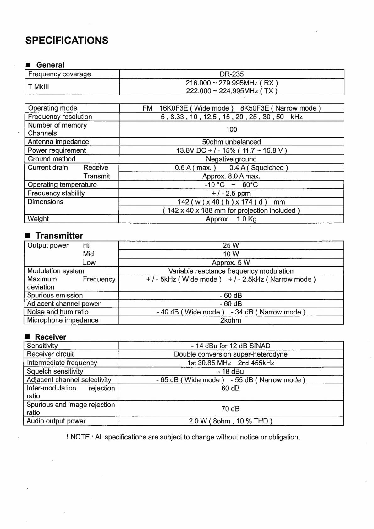
SPECIFICATIONS
PARTS
LIST
GING
RA
re
cadvcned
cs
cee
sad
si
wana
eeeamtoeneunreosaecees
2
CPO
UAE
ciccrcaccadaviehareseedineyteuseed
21,22
TRANSMIT
T
ER:
ccdiccsscscc.cesestewabreaddamees
sates
2
DARIN
NE
auictacctactercacetedesn
tage
nhedes
22-25
RECEIVE
Riscse2.dscaceratconssoce
races
2
Mechanical
Parts...............cccceceeeeeeees
25
Packing
Parts.........ccccsssccesseseeneenecnens
25
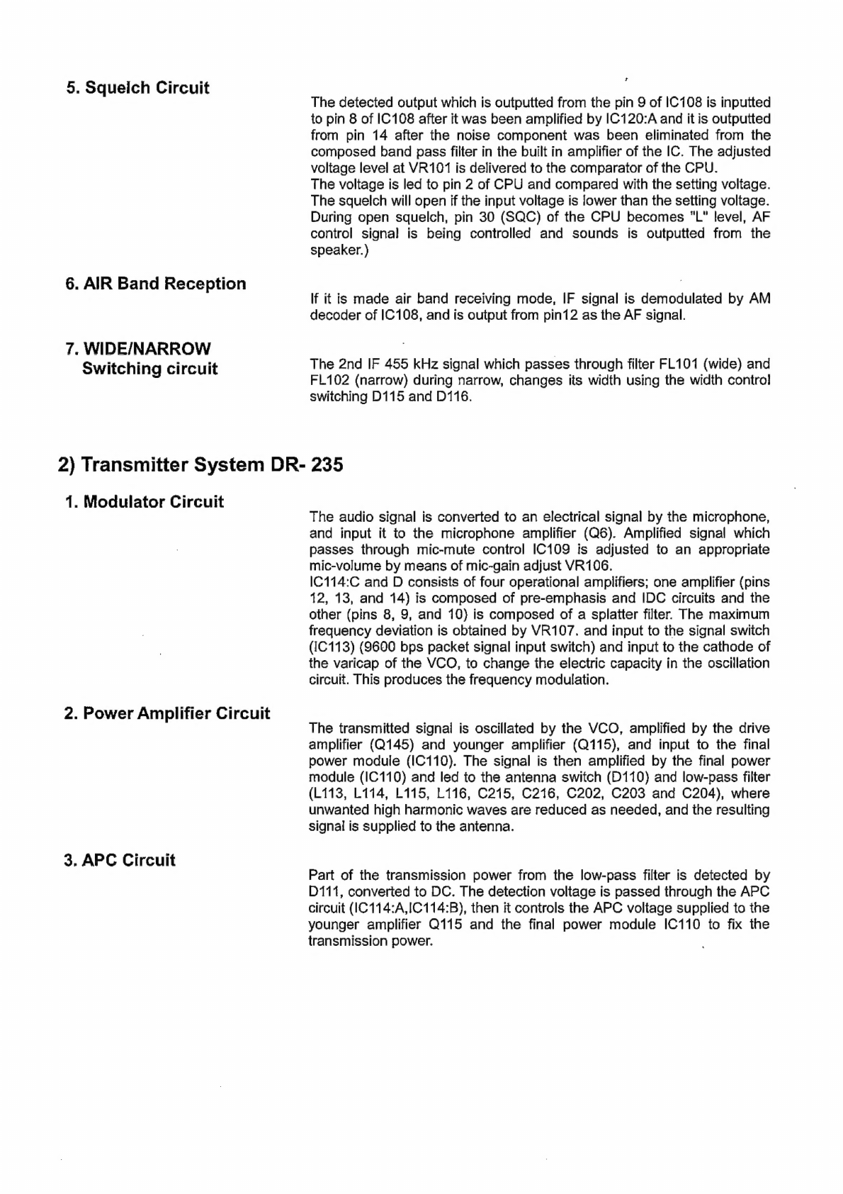
CIRCUIT
DISCRIPTION
ACCESSORIES
oy
seieswestcnutiaseueteiotenes
25
1)
Receiver
System
DR-235.............ccceeseeeeens
3,4
ACCESSORIES
(SCREW
SET)...........
25
2)
Transmitter
System
DR-235............0cceeeeees
4
TING
(dG)
oan
cau
eieeavaireaineesoninevaass
26
3)
PLL
Synthesizer
Circuit
DR-235................0.
5
TNC
(EJ41U)
Packing
Parts................
27
4)
CPU
and
Peripheral
Circuit........................
5,6
-
5)
Power
Supply
Circuit.......00.....000.:cccce
eee
6
DR-235
ADJUSTMENT
6)
M38268MCAO75GP
(XA1130)..........0....0..
7-9
1)
Adjustment
Spot................ccccee
eee
ee
eee
28
2)
VCO
and
RX
Adjustment
Specification...
29
SEMICONDUCTOR
DATA
3)
TX
Adjustment
Specification...............
30
1)
NJM7808FA
(XA0102)...........ccceceeeeceseeeeees
10
4)
RX
Test
Specification...........
eee.
31
2)
TC4S66F
(XA0115)..........cccseccecceesserecceeees
10
5)
TX
Test
Specification..............ccccceees
32
3)
AN8010M
(XA0119).............ccccecscscesessseers
10
4)
TC4W53FU(XA0348).....6...cccceeceeeeeeeeeeees
10
PC
BOARD
VIEW
5)
TA31136FN
(XA0404)...0.
0
cece
eee
ee
eee
11
1}
CPU
Unit
Side
A
DR-235
(UP0579)......
33
6)
LA4425A
(XA0410)........
cee
ces
cece
e
cee
ee
eee
eees
11
2)
CPU
Unit
Side
B
DR-235
(UP0579)......
33
7)
BR24L32FJ
(XAQ604Z).........
00.
cccec
cee
eee
scene
11
3)
MAIN
Unit
Side
A
DR-235
(UP0579).....
34
8)
L88MSOS5TLL
(XA0675).............
cc
ccec
ees
ee
eens
12
4)
MAIN
Unit
Side
B
DR-235
(UP0579)....
34
9)
S-816A50AMC
(XAQ9Q25).......000ccceseee
cesses
12
5)
TNC
Unit
Side
A(UP0402)
(option)......
35
10)
LM2904PWR
(XA1103)...........ccececeece
eee
eeees
12
6)
TNC
Unit
Side
B
(UP0402)
(option)......
35
14)
LM2902PWR
(XA1106).............e
cece
ee
ee
ee
eens
12
12)
MB15E07SR
(XA1107).......0....ccecee
eee
eee
eeeee
13.
SCHEMATIC
DIAGRAM
13)
S-80845CLNB
(XA1120)...........ccceccecneeeeens
14
1)
CPU
Unit
DR-235.............
cee
cece
eee
eee
36
14)
BU4052BCFV
(XA1229)........
cece
eseecavenens
14
2)
MAIN
Unit
DR-235.....0..0...
eee
cece
eee
es
37
45)
-S=AVAO
(KA
T2380
Msi
cectcwadwigiesaisetouces
ness
15
3)
TNC
Unit
(option)..................
cee
38
16}
Transistor,
Diode
and
LED
Outline
Drawing...
16
17)
LCD
Connection
(TTR3626UPFDHN)..........
17
BLOCK
DIAGRAM
BY
DR
20565
Baste
crake
nee
39
EXPLODED
VIEW
1)
LCDASSEMbDIY..............cccccceccesensceseeeeeees
18
2)
Top
and
Front
View...............c.cccceseeseee
eens
19
SO)
BOUGHT
VIOW:
cvisicticsscn
ais:
seeds
seccdcecatuesevaees
20
ALINCO,
INC.