Alinco DR-135TMkIII User manual

Rhein Tech Laboratories, Inc. Client: Alinco, Inc.
360 Herndon Parkway Model: DR-235TMkIII
Suite 1400 Standards: FCC 15.121
Herndon, VA 20170 & IC RSS-215
http://www.rheintech.com Report: 2006179
Page 23 of 41
Appendix J: Manual
Please see the following pages.


1
Contents
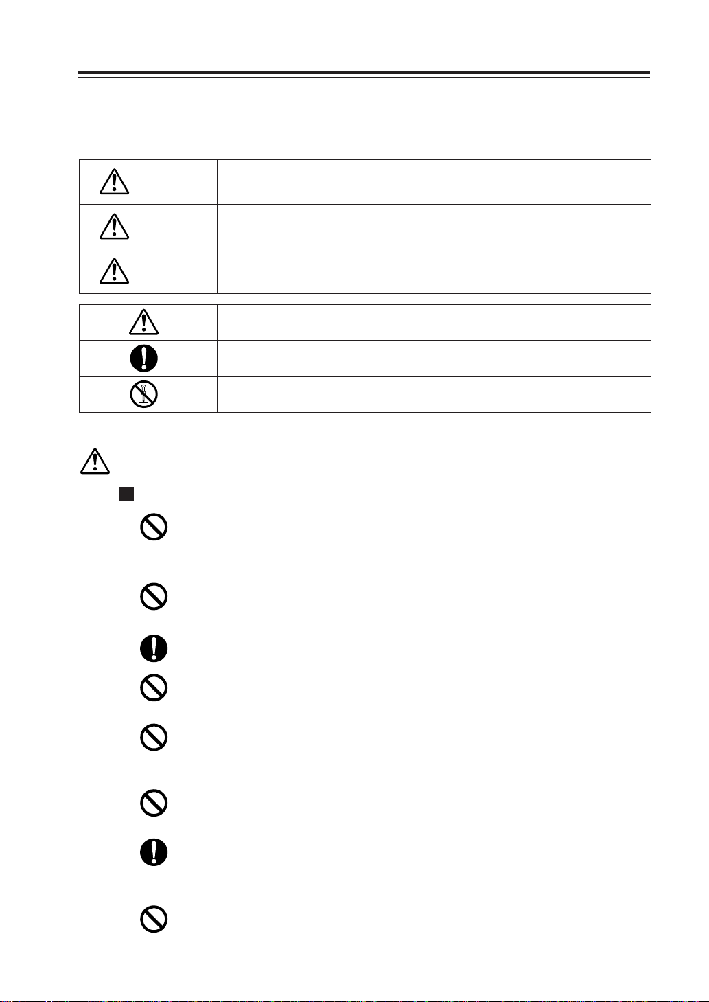
Warning ............................................................................... 3
Before operating the transceiver...................................... 7
Introduction ........................................................................ 8
1. New and Innovative Features ........................................ 9
2. Standard Accessories.................................................. 10
3. Initial Installation .......................................................... 11
For a base station set up ..................................................................... 11
For a mobile station set up .................................................................. 12
External power supply control & Power lamp functions....................... 13
Power supply voltage display function................................................. 13
4. Part Names and Functions .......................................... 14
Front Panel .......................................................................................... 14
Rear Panel........................................................................................... 15
Display ................................................................................................. 16
Microphone .......................................................................................... 17
5. Basic Operations.......................................................... 18
Turning the unit on and off ................................................................... 18
Audio Volume level setting .................................................................. 18
Squelch level setting............................................................................ 18
VFO mode ........................................................................................... 19
[Change frequency by the channel step] ................................ 19
[Change frequency by 1 MHz step] ........................................ 19
Changing the channel step .................................................................. 20
REPEATER (DUPLEX) Operation ....................................................... 20
CTCSS / DCS setting .......................................................................... 21
Memory Mode...................................................................................... 22
[Memory programming]........................................................... 22
[Programmable data in the memory channel] ......................... 26
CALL mode .......................................................................................... 24
To receive signals ................................................................................ 24
To transmit ........................................................................................... 25
6. Parameter Setting Mode .............................................. 26
Channel Step setting ........................................................................... 27
Scan Type............................................................................................ 27
Beep Sound ......................................................................................... 27
Time-Out-Timer.................................................................................... 28
TOT Penalty......................................................................................... 28
APO - Auto Power OFF ....................................................................... 29
Tone-Burst-Frequency ......................................................................... 29
Busy-Channel-Lock-Out ...................................................................... 29
Theft Alarm .......................................................................................... 29

2
Contents
Alphanumeric Tag ................................................................................ 30
Dimmer ................................................................................................ 30
7. Advanced Operations .................................................. 31
SCANNING FUNCTION ...................................................................... 31
[VFO Scan] ............................................................................. 31
[Memory scan] ........................................................................ 31
• Program scan ....................................................................... 32
• Tone Scan ............................................................................. 32
• DCS scan ............................................................................. 33
KEY-LOCK FUNCTION ....................................................................... 33
TONE BURST...................................................................................... 33
Digital voice communication ................................................................ 34
WIDE / NARROW (Reduction of the Mic Gain/Deviation) ................... 34
AUTO-DIALER..................................................................................... 35
THEFT ALARM .................................................................................... 36
AM Mode Reception (DR235TMk only)............................................. 37
CABLE CLONE ................................................................................... 38
8. PACKET OPERATION ................................................... 39
[To operate packet using EJ-41U]........................................... 39
[To operate packet using an external TNC]............................. 41
[To operate APRS®] ................................................................ 42
[SET UP] ................................................................................. 43
[APRS Operation] ................................................................... 43
9. Remote Control Operation .......................................... 44
[List of Remote Control Keys] ................................................ 44
[Entering a frequency directly] ................................................ 45
[Entry method depending on tuning step] ............................... 45
10. Maintenance / Reference ........................................... 46
Reset ................................................................................................... 46
Trouble Shooting ................................................................................. 47
11. Optional accessories ................................................. 48
12. Specifications ............................................................. 49
Appendix........................................................................... 50
TNC Commands List ........................................................................... 50

3
Warning
To prevent any hazard during operation of Alinco's radio product, in this manual and on the product you
may find symbols shown below. Please read and understand the meanings of these symbols before
starting to use the product.
Do not drive while handling the radio for your safety. It is recommended that you
check local traffic regulations regarding the use of radio equipment while driving.
Some countries prohibit the operation of transceiver while driving.
Do not use this product in close proximity to other electronics devices, especially
medical ones. It may cause interference to those devices.
Keep the radio out of the reach of children.
In case a liquid leaks from the product, do not touch it. It may damage your skin.
Rinse with plenty of cold water if the liquid contacted your skin.
The manufacturer declines any responsibilities against loss of life and/or property due
to a failure of this product when used to perform important tasks like life-guarding,
surveillance, and rescue.
Never operate this product in facilities where radio products are prohibited for use
such as aboard aircraft, in airports, in ports, within or near the operating area of
business wireless stations or their relay stations.
Use of this product may be prohibited or illegal outside of your country. Be informed
in advance when you travel.
Do not use multiple radios in very close proximity. It may cause interference and/or
damage to the product(s).
Danger This symbol is intended to alert the user to an immediate danger that may
cause loss of life and property if the user disregards the warning.
This symbol is intended to alert the user to a possible hazard that may
cause loss of life and property if the user disregards the warning.
This symbol is intended to alert the user a possible hazard that may cause
loss of property or injure the user if the warning is disregarded.
Alert
Caution
Alert symbol. An explanation is given.
Warning symbol. An explanation is given.
Instruction symbol. An explanation is given.
Alert
Environment and condition of use:

4
Warning
Do not open the unit without permission or instruction from the manufacturer.
Unauthorized modification or repair may result in electric shock, fire and/or
malfunction.
Do not operate this product in a wet place such as shower room. It may result in
electric shock, fire and/or malfunction.
Be sure to reduce the audio output level to minimum before using an earphone or a
headset. Excessive audio may damage hearing.
Do not place the product in a container carrying conductive materials, such as water or
metal in close proximity to the product. A short-circuit to the product may result in
electric shock, fire and/or malfunction.
Do not touch the heatsink (on/around the unit mostly found on mobile-base units) as it
may become very hot during/after the operation that may risk burn your skin.
Handling this product:
The manufacturer declines any responsibilities against loss of life and property due to
a failure of this product when used with or as a part of a device made by third parties.
Use of third party accessory may result in damage to this product. It will void our
warranty for repair.
Risk of explosion if battery is replaced with an incorrect type.
Dispose of, or recycle used batteries according to your local regulations.
Do not handle a power-supply with a wet hand. It may result in electric shock.
Do not connect cables in reverse polarity. It may result in electric shock, fire and/or
malfunction.
Do not plug multiple devices including the power-supply into a single wall outlet. It
may result in overheating and/or fire.
About power-supply:
Securely plug the power-supply to the wall outlet. Insecure installation may
result in short-circuit, electronic shock and/or fire.
Use only appropriate, reliable power supply of correct voltage and capacity.
Do not plug the power-supply into the wall socket if the contacts are dirty. Short-
circuiting and/or overheating may result in fire, electric shock and/or damage to the
product.
Do not modify or remove fuse-assembly from the DC-cable. It may result in fire,
electric shock and/or damage to the product.

5
Warning
Do not use the cable at any other than the specified ones. It may result in electric
shock, fire and/or malfunction.
Do not handle cigar-cable with a wet hand. It may result in electric shock.
Cigar-lighter cable (for optional Igunition-key ON/OFF operation):
In case of the following situation(s), please turn off the product, switch off the source of
power, then remove or unplug the power-cord. Please contact your local dealer of this
product for service and assistance. Do not use the product until the trouble is resolved. Do
not try to troubleshoot the problem by yourself.
• When a strange sound, smoke and or strange odor comes out of the product.
• When the product is dropped or the case is broken or cracked.
• When a liquid penetrated inside.
• When a power-cord ( including DC-cables, AC-cables and adapters) is damaged.
In case of emergency:
For your safety, turn off then remove all related AC-lines to the product and its
accessories from the wall outlet if a thunderstorm is likely.
Turn off the unit, remove the mobile antenna from its base and keep it in the vehicle if
a thunderstorm is likely.
Please read cautions regarding the lightning-protection on page 7 also.
Do not open the unit and its accessories. Please consult with your local dealer of this
product for service and assistance.
Maintenance
Do not use the product in proximity to a TV or a radio. It may cause interference or
receive interference.
Do not install in a humid, dusty or insufficiently ventilated place. It may result in
electric shock, fire and/or malfunction.
Do not install in an unstable or vibrating position. It may result in electric shock, fire
and/or malfunction when/if the product falls to the ground.
Do not install the product in proximity to a source of heat and humidity such as a
heater or a stove. Avoid placing the unit in direct sunlight.
Do not modify, dismantle, incinerate, or immerse the batteries.
Please check your local regulations for details on recycling option or disposal of the
batteries in your area.
CAUTION
Environment and condition of use:

6
Warning
About power-supply
Use only reliable power supply of specific DC output range and be mindful of the
polarity of the cables and DC jack.
Always turn off the power supply when connecting or disconnecting the cables.
European users: When a transceiver is powered from an external DC power source
(adapter, power supply, cigar-plug etc), make sure that this power supply has approval
to the level of IEC/EN 60950-1.
When using an external antenna, make sure that the antenna ground is not common
with the ground of the power supply.
Use a clean, dry cloth to wipe off dirt and condensation from the surface of the
product. Never use thinner or benzene for cleaning.
Turn off and remove the power-source (AC cable, DC cable, battery, cigar-cable,
charger adapter etc) from the product when the product is not in use for extended
period of time or in case of maintenance.
Never pull the cord alone when you unplug AC cable from the wall outlet.
Do not connect devices other than specified ones to the jacks and ports on the product.
It may result in damage to the devices.
About transceiver

7
Before operating the transceiver
Notice to California resident users
The product that comes with this manual is free from dangerous material such as lead
and cadmium as per RoHS order of EU.
The transceiver has no protection against lightning.
The user is responsible for providing adequate protection if he uses the device at
home and installs the antenna outdoor. Be aware that any outdoor antenna creates a
direct path for lighting current (more than 10kA) to the transceiver. This path exists
whether the device is turned ON or OFF.
Any vehicle does not present a safe environment during lightning. This environment
becomes much moe dangerous if an outdoor antenna is installed on the car. Move the
antenna and its cable into the car at the first sight of forthcoming thunderstorm and
lightning.
Attention
• Do not remove the case or touch the interior components.
Tampering can cause equipment trouble.
•Do not use or keep the transceiver where it is exposed to direct sunlight, dusty
places, or near sources of heat.
•Keep the transceiver away from TV's or other equipment
when it interferes with reception.
•When transmitting for long periods of time at high power,
the transceiver might overheat.
•Turn the power off immediately if the transceiver emits
smoke or strange odors. Ensure the transceiver is safe,
then bring it to the nearest Alinco service center.
•An operator's license is required for this device.

8
Introduction
Thank you very much for purchasing this excellent Alinco transceiver. Our products
are ranked among the finest in the world. This radio has been manufactured with state
of the art technology and it has been tested carefully at our factory. It is designed to
operate to your satisfaction for many years under normal use.
PLEASE READ THIS MANUAL COMPLETELY TO LEARN ALL THE
FUNCTIONS THE PRODUCT OFFERS. WE MADE EVERY ATTEMPT TO
WRITE THIS MANUAL TO BE AS COMPREHENSIVE AND EASY TO
UNDERSTAND AS POSSIBLE. IT IS IMPORTANT TO NOTE THAT SOME OF
THE OPERATIONS MAY BE EXPLAINED IN RELATION TO INFORMATION IN
PREVIOUS CHAPTERS. BY READING JUST ONE PART OF THE MANUAL,
YOU RISK NOT UNDERSTANDING THE COMPLETE EXPLANATION OF THE
FUNCTION.

9
1. New and Innovative Features
Your new radio features some of the most advanced functions and reliable engineering
available anywhere. The ALINCO design philosophy is focused on developing innova-
tive usable features, including the following:
•Three different styles of display are available on a large LCD panel including fre-
quency, channel number or 7 digit alphanumeric label.
The dimmer (bright/dim) makes it easier to read the display at night. (T/E models only)
•Simple, clean layout of keys and knobs ensure convenient operation.
•High-quality materials are used throughout the product and a huge heat sink around the
chassis ensures stable and durable operation.
•Conventional or narrow FM mode can be selected.
•AM Air-band reception capability. (available on DR135TMk / 235TMk only)
•100 fully programmable memory channels with alphanumeric memory channel labels.
•ADATA port is located on the front panel for easy access to external accessory connec-
tions. A DSUB9 port is available on the rear to connect a PC for 1200/9600bps packet
operation. (T/E models only)
•CTCSS, DCS and 4 different Tone-Bursts are standard for selective calling and re-
peater access worldwide.
•The Theft Alarm feature gives an extra measure of security for mobile installation.
• The transceiver has a cable clone capability.
•The optional EJ-41U board is available for data communications such as APRS®or
packet, without an external TNC. (T/E models only)
DR-135/235/435MkIIIseries / feature comparison chart
Feature
DR-135TMkIII
DR-235TMkIII
DR-435TMkIII
DR-135/435EMkIII
DR-135FXE
DR-435FXE
Microphone
EMS-57 DTMF
EMS-57 DTMF
EMS-57 DTMF
EMS-53 Plain
EMS-53 Plain
EMS-53 Plain
TX frequency
USA Amateur
USA Amateur
USA Amateur
European Amateur
European Amateur
European Amateur
RX frequency*
136-174MHz + airband in AM
216-280MHz (include AM)
350-511.995MHz
European Amateur
European Amateur
European Amateur
Freq. Stability
+/-2.5ppm
+/-2.5ppm
+/-2.5ppm
+/-2.5ppm
+/-5ppm
+/-2.5ppm
DATA port(DSUB9)
Standard
Standard
Standard
Standard
N/A
N/A
Feature TNC/Packet
operation Digital Voice
Modem Car-key ON/OFF port LCD
brightness DC voltage
display
DR-135/435TMkIII
DR-235TMkIII
DR-135/435EMkIII
DR-135/435FXE
Optional EJ-41U
Optional EJ-41U
Optional EJ-41U
N/A
Optional EJ-47U
Optional EJ-47U
Optional EJ-47U
N/A
Standard
Standard
Standard
N/A
Bright/Dim
Bright/Dim
Bright/Dim
N/A
Standard
Standard
Standard
N/A
* The specifications on page49 are valid only within the amateur radio frequencies.

Tapping screws
(M5*20mm) 4pcs. (AJ0003)
Black screws (M4*8mm)
4pcs. (AE0012)
Screws (M5*20mm)
4pcs. (AA0013)
Hexagonal nut (M5) 4pcs.
(AN0002) Small (spanner) wrench.
(FM0079)
Washer (AZ0010)
S-washer (AZ0009)
Spare fuses (a pair)
2pcs. (EF0005)
(15A)
10
2. Standard Accessories
Carefully unpack to make sure the following items are found in the package in addition to this manual:
•Transceiver
•Mobile mounting bracket. (FM0078Z)
•DC power cable with fuse holder (UA0038)
•Alarm cable A (with wire) (UX1259)
(T/E models only)
•
Alarm cable B (extension use) (UX1260)
(T/E models only)
•Theft Alarm stickers 2pcs. (PR0454)
(T/E models only)
•Instruction manual (PS0513B)
•Hardware kit for bracket
•Microphone EMS-53 or EMS-57 (with
DTMF keypad)
The standard accessories may vary slightly depending on the version you have purchased. Please contact
your local authorized Alinco dealer should you have any questions. ALINCO and authorized dealers are
not responsible for any typographical errors there may be in this manual. Standard accessories may
change without notice.
Warranty Policy:
Please refer to any enclosed warranty information or contact your authorized Alinco dealer / distributor
for the warranty policy before purchase.

11
3. Initial Installation
* When a transceiver is powered from an external DC power source (adapter, power supply, cigar-
plug etc), make sure that this power supply has approval to the level of IEC/EN 60950-1.
Antenna
External speaker
(if used)
Microphone
rear panel
(T/E models only)
For a base station set up
The Transceiver requires a 12-13.8VDC negative grounded power source.
Use a regulated power supply capable of providing continuous current of 12A or more.
Power supplies that do not meet those specifications may cause malfunction and/or damage to the
radio and will void the warranty. Alinco offers excellent communication-grade power supplies as
optional accessories. Please contact your local authorized Alinco dealer.
DC
power supply
*
DC power cable
Black lead
Red lead
1
2
CAUTION: The body (heatsink) of this product may become very hot during/after the operation.
Never touch the unit until it cools down.
Connect the microphone to the front panel of the transceiver.
Connect antenna port to a 50 ohm antenna that is tuned to the band, using good quality 50 ohm
coaxial cable.

12
3. Initial Installation
For a mobile station set up
Location
The transceiver may be installed in any position in your car, where the controls and microphone are easily accessible and it
does not interfere with the safe operation of the vehicle or the performance of the set. If your vehicle is equipped with air
bags, be certain your radio will not interfere with their deployment. If you are uncertain about where to mount the unit,
contact your vehicle's manufacturer. While installing the unit in less ventilated place, please be aware that DC cables never
touch the heatsink of the unit. The heatsink may become excessively hot if proper ventilation is not availble while transmit-
ting at, or similar to 100% duty-cycle, therefore there is risk of melting insulation of the DC cables and the consequent
short-circuiting of them.
Installing a Mobile Antenna
Use a 50 ohm coaxial cable to connect the antenna. Mobile antennas require an appropriate mount-
ing base for proper installation and operation. For more information, see the documentation for
your antenna.
Installing theTransceiver
See the figure on the below.
Screw-fixed
base
Magnet base
Car body
Washer (M5)
Tapping screw
(M5 x 20 mm)
Mounting bracket
CAUTION: After installing your antenna, ensure that you have the best possible SWR reading.
High RF environments can cause severe damage to your unit. Ensure that you are not
in a high RF environment when operating the transceiver.
CAUTION: RF Hazard Warning
The electro-magnetic (radio Frequency) exposure level of this device may exceed the
European standards of the hazard level when transmitting at the high-power setting
while connected to a unity gain antenna at a distance of 63cm or less from the opera-
tor. Furthermore, the hazardous RF exposure level depends on the conditions of the
combination of the antenna gain, distance from the operator, output setting and instal-
lation environment, therefore the operator may be exposed to stronger RF even at a
distance of more than 63cm. For safety purpose, it is recommended that the antenna
be installed outside of,and as far as possible from, the operator's area. Avoid using an
excessively high-gained antenna in case the distance between the operator and the
antenna is very limited. Always use the minimum necessary output power for commu-
nications.

13
3. Initial Installation
External power supply control & power lamp functions
Be sure the vehicle has a negative-ground, 12VDC electric system before installation. Connect the
provided DC cable directly to the battery as shown below to minimize any possible ignition noise.
Be sure the vehicle has a large capacity battery as the use of the transceiver may overload the
electric system of the vehicle.
If the ignition-key on/off feature is desired (optional feature), use the optional EDC-37 (For direct
connection to the circuit on the vehicle) or EDC-36 (for a Cigar-Plug connection) cable. Connect
one of the cables between the ACC terminal or a Cigar-Plug that operates with the vehicle ignition
or ACC switch on the vehicle and EXT POWER jack on the rear side of the unit. (Note: In many
cars, the cigar-lighter plug is always powered. If this is the case, you cannot use it for the ignition
key on/off function.) If this option is selected, the unit can be turned on/off either manually or
automatically in accordance with the ignition key position:
1. When the ignition key is turned toACC or ON (Start) position with the radio turned
off, the power switch illuminates. The illumination will be turned off when the igni-
tion key is turned to the off position. To turn on the unit, press the power switch
manually while it is illuminated (while ignition key is at ACC or ON position).
2. When the ignition key is turned toACC or ON position with the radio's power switch
on, the unit turns on automatically and the power switch will be lit. Turn the ignition
key to OFF position or manually turn the power switch off to shut down the radio.
The power consumption when using the additional cable is 5mA.
For operation without this option, use the power switch to turn the unit on/off.
Power supply voltage display function
After connecting the transceiver to the power supply, the supply voltage can be confirmed by
pressing the SQL key together with the FUNC key. The supply voltage to the transceiver is then
seen on the display.
The transceiver will return to its normal operation when the power is switched OFF.
The display immediately changes as the voltage supply changes.
It also displays voltage during transmission. (T/E models only)
IMPORTANT:
The range of the displayed voltage is only from 7V - 16VDC. Because the displayed value
is approximate, please use a voltmeter when a more precise reading is desired.
DC cable
Battery
Cigar-Plug connection
ACC terminal
Ext. Power jack

14
4. Part Names and Functions
Front Panel
10
12
4 5 67893
11
2
1
•Primary Functions
No.
KeyFunction
1PWR Power turns ON / OFF whenever the key is pressed.
2Volume knob Adjusts the AF audio level.
3Dial
Changes the frequency, memory channel and scan direction.
4 FUNC/SET Sets the function mode to access additional settings.
5V/M/MW Switches between VFO mode and memory mode.
6MHZ/SHIFT Changes the frequency in 1 MHz steps.
7
TS/DCS/LOCK
Sets the tone squelch and DCS setting.
8CALL/H/L Switches to CALL mode.
9SQL/D Sets the squelch level
10
DATA Terminal
Used in clone and theft alarm functions.
11
TX Light indicator
Lights during transmission.
12
Mic. Connector
Connection port for supplied microphone.
•Functions which can be activated while F appears, after
pressing the FUCN Key.
No.
KeyFunction
4FUNC/SET
Confirms selection of other functions and exits the function mode.
5V/M/MW Programs the data in to memory channel.
6MHZ/SHIFT Sets the shift direction and the offset frequency.
7
TSDCS/LOCK
Sets the key lock function.
8CALL/H/L Switches between HI, MID, and LOW power transmission.
9SQL/D Accesses the packet communication mode. (T/E models only)
AM reception(DR-235TMk only)

15
4. Part Name of Functions
Rear Panel
3
21 4
No.
KeyFunction
1Ext. Power jack Terminal for connecting optional EDC-37 for
use with ignition key on/off function. (T/E
models only)
2External Speaker Port For optional external speaker
3DSUB-9 Connector Terminal where external TNC may be con-
nected for packet use. With optional EJ-41U,
connects internal TNC to the computer. (T/E
models only)
4Antenna Connector Connection for 50 ohm coaxial cable and
antenna.
•
Functions that can be activated while pressing the FUNC Key
No.
KeyFunction
1PWR Reset to factory default settings.
5V/M/MW Erase the memory.
6MHZ/SHIFT Switches to wide / narrow mode.
7
TSDCS/LOCK
Sets the auto dialer.
8CALL/H/L Accesses the clone function mode.
9SQL/D Accesses the power supply voltage indication mode. (T/E
models only)
• Functions that require continuous pressing to be activated.
No.
KeyFunction
4 FUNC/SET When pressed for 2 seconds, accesses the set mode.
6MHZ/SHIFT When pressed, within 1 second the scan start.
9SQL/D
When pressed, within 1 second the monitor function is on.

16
4. Part Names and Functions
Display
10
11
12131416 15171819
8
3
9
1
2
4
5 6 7
No.
KeyFunction
1SQL Appears when setting the squelch level.
2MAppears when in memory mode.
3Indicates the memory channel number in memory mode.
4
.Decimal point
Appears when setting the theft alarm function.
5
.Decimal point
Appears when setting the skip level.
6
.Decimal point
Indicates the decimal point of frequency and the scanning function.
7Indicates the frequency or memory name.
8Appears when a signal is being received.
9S-meter
Indicates the relative signal strength level of transmission / reception.
10 Appears when in packet mode and digital voice mode.
11 Appears when setting the key lock.
12 DCS Appears when setting the DCS.
13 Appears when setting the tone squelch.
14 +- Appears when setting the shift.
15 A Appears during AM reception.(135TMk /235TMk only)
16 Nar Appears when in narrow band reception mode.
17 Lo Appears when transmission power is set to LOW.
18 Mi Appears when transmission power is set to MID.
19 Appears when FUNC Key is pressed.

17
4. Part Name of Functions
Microphone
Mic. Connector Diagram (While looking in the front view of the con-
nector)
17
26
345
8
PTT
MIC MIC GND
Remote control
DC 5V
DOWN
GND
UP
T version E version
No.
KeyFunction
1UP
Increase the frequency, memory channel number, or setting value.
2DOWN
Decrease the frequency, memory channel number, or setting value.
3PTT Press the PTT(Push-To-Talk)key to transmit.
4DTMF DTMF tone keys
DTMF / REMOTE
5
Switch
6Lock Switch Locks out the UP and DOWN keys.
7MIC Speak here during transmission.
Set to DTMF when you don’t want to operate remote con-
trol functions. So that DTMF keys do not function except
during transmit to send DTMF codes manually.
This manual suits for next models
6
Table of contents
Other Alinco Transceiver manuals

Alinco
Alinco DX-70 User manual

Alinco
Alinco DR-140T User manual

Alinco
Alinco DR-150T User manual

Alinco
Alinco DR-135 User manual

Alinco
Alinco DX-10 User manual

Alinco
Alinco DR-M03SX User manual

Alinco
Alinco DJ-CRX5 User manual

Alinco
Alinco DJ-580T User manual

Alinco
Alinco DJ-FX446 User manual

Alinco
Alinco DJ-191 User manual

Alinco
Alinco DX-70T User manual

Alinco
Alinco DJ-V5T/E User manual

Alinco
Alinco DJ-580T User manual

Alinco
Alinco DR-610T User manual

Alinco
Alinco DJ-G7 User manual

Alinco
Alinco DR-112E User manual

Alinco
Alinco DJ-S11 User manual

Alinco
Alinco DR-510T User manual

Alinco
Alinco DX-77T User manual

Alinco
Alinco DJ-162TD User manual