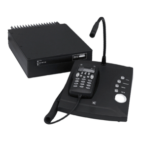
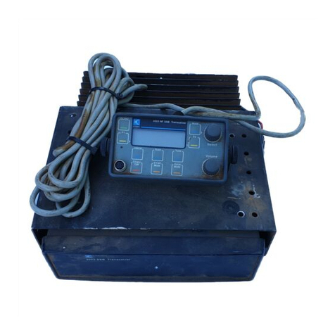
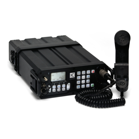
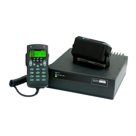
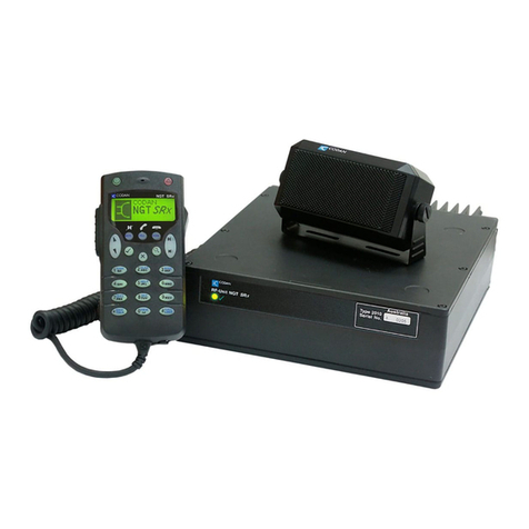
Codan 8525B Series Operating manual

HF SSB Transceiver
8525B/8528 series
Technical Service Manual
Volume 1
1989 Codan Pty Ltd.
ACN 007 590 605
Order code 15-02036
Issue 6, November 1995

Head Office
Codan Pty Ltd
ACN 007 590 605
81 Graves Street
Newton
South Australia 5074
International +61 8 8305 0311
Facsimile +61 8 8305 0411
Marketing Offices
Codan (U.K.) Ltd
Gostrey House
Union Road
Farnham, Surrey GU9 7PT
United Kingdom
International +44 1252 717 272
Facsimile +44 1252 717 337
Telex 858355
Codan Pty Ltd
Suite 11A, 2 Hardy Street
South Perth
Western Australia 6151
International +61 8 9368 5282
Facsimile +61 8 9368 5283

Publication No: 15-02036 Issue 6
Table of Contents
1 General Information
1.1 Introduction ........................................................................................................1-1
1.2 Specifications .....................................................................................................1-2
1.2.1 General ............................................................................................1-2
1.2.2 Receiver...........................................................................................1-4
1.2.3 Transmitter......................................................................................1-6
1.2.4 Rear Panel Connectors ....................................................................1-7
1.2.5 Front Panel Connector...................................................................1-10
1.3 Options and Accessories ..................................................................................1-11
1.3.1 Options..........................................................................................1-11
1.3.2 Accessories....................................................................................1-12
1.4 Abbreviations ...................................................................................................1-13
1.5 Circuit Reference Designations........................................................................1-20
1.6 Units.................................................................................................................1-21
1.7 Unit Multipliers................................................................................................1-21
2 Block Diagram
3 Brief Description
3.1 General ...............................................................................................................3-1
3.2 Receive...............................................................................................................3-1
3.3 Transmit .............................................................................................................3-2
3.4 Synthesizers........................................................................................................3-2
3.5 Display, Control and Switching .........................................................................3-3
3.6 External Power Amplifiers.................................................................................3-3

ii Table of Contents 8525B/8528 Technical Service Manual
Issue 6 Publication No: 15-02036
4 Technical Description
4.1 Control and Supply Voltages..............................................................................4-1
4.1.1 Supply Voltages ..............................................................................4-1
4.1.2 Power and Control Lines.................................................................4-2
4.1.3 Overvoltage and Reverse Voltage Protection..................................4-2
4.1.4 Transceiver Power On/Off ..............................................................4-2
4.1 5 High Power Transceiver Protection and Power On/Off..................4-3
4.2 Receiver..............................................................................................................4-4
4.2.1 Input Filters .....................................................................................4-4
4.2.2 Mixers, First IF Amplifiers and Filters ...........................................4-4
4.2.3 Noise Blanker..................................................................................4-5
4.2.4 IF Crystal Filter and Amplifier........................................................4-5
4.2.5 Demodulator....................................................................................4-5
4.2.6 Audio Mute .....................................................................................4-6
4.2.7 Volume Control and Audio Amplifier............................................4-6
4.3 Transmitter Exciter.............................................................................................4-7
4.3.1 Microphone Amplifier.....................................................................4-7
4.3.2 Modulator........................................................................................4-7
4.3.3 Crystal Filter....................................................................................4-8
4.3.4 Mixers, IF Filters and IF Amplifier.................................................4-8
4.4 Local Oscillators.................................................................................................4-9
4.4.1 Voltage Controlled Oscillators (VCO)............................................4-9
4.4.2 Phase/Frequency Detectors and Dividers........................................4-9
4.4.3 Lock Signals..................................................................................4-10
4.4.4 Loading of Frequency Data to Synthesizers..................................4-10
4.4.5 1650/1647kHz Local Oscillators...................................................4-11
4.4.6 Clarifier .........................................................................................4-11

8525B/8528 Technical Service Manual Table of Contents iii
Publication No: 15-02036 Issue 6
4.5 Microprocessor Controller PCB (04-02451 & 04-03031)................................4-12
4.5.1 Microcontroller Bus ......................................................................4-12
4.5.2 Internal I2C Bus.............................................................................4-13
4.5.3 External Bus..................................................................................4-14
4.5.4 Reset and Watchdog Circuit..........................................................4-14
4.5.5 RS-232 Port (ALE Option Only)...................................................4-14
4.6 Motherboard and Chassis (02-02453)..............................................................4-15
4.6.1 Power Supplies..............................................................................4-15
4.6.2 Antenna Control Facility...............................................................4-15
4.6.3 Extended or Remote Control—Option R......................................4-15
4.6.4 External Microphone Audio Clamp..............................................4-16
4.6.5 Additional Audio Facilities—Option RC......................................4-16
4.6.6 Headphone Output—Option PH ...................................................4-16
4.6.7 CW Facility—Option M................................................................4-16
4.6.8 External Selective Call or RTTY—Option PS..............................4-16
4.6.9 AGC Dump Circuit .......................................................................4-17
4.7 8525B Front Panels and Control Head.............................................................4-17
4.7.1 Display PCB..................................................................................4-17
4.7.2 Switch Matrix................................................................................4-18
4.7.3 Digiswitches..................................................................................4-18
4.7.4 Microphone Amplifier and Interface.............................................4-18
4.8 8528 Front Panel and Control Head.................................................................4-19
4.8.1 Display PCB, LCD........................................................................4-19
4.8.2 Indicator and Display Dimming....................................................4-20
4.8.3 Links..............................................................................................4-20
4.8.4 Switch Matrix................................................................................4-21
4.8.5 Microphone Amplifier and Interface.............................................4-21
4.8.6 8532 Display Head........................................................................4-21

iv Table of Contents 8525B/8528 Technical Service Manual
Issue 6 Publication No: 15-02036
4.9 PA and Filters (04-02452)................................................................................4-24
4.9.1 Introduction...................................................................................4-24
4.9.2 PTT Control...................................................................................4-24
4.9.3 Gain Control Stage........................................................................4-24
4.9.4 Pre-Driver Stages ..........................................................................4-24
4.9.5 Driver Stage...................................................................................4-25
4.9.6 Output Stage and Bias Regulator ..................................................4-25
4.9.7 Output Filters and Control.............................................................4-25
4.9.8 ALC Control..................................................................................4-26
4.9.9 Transmit Indicator.........................................................................4-27
4.10 PA Exciter Interface.........................................................................................4-27
4.10.1 Introduction...................................................................................4-27
4.10.2 Control Lines.................................................................................4-27
4.10.3 Power On/Off................................................................................4-27
4.10.4 PTT Circuit....................................................................................4-27
4.10.5 Transmit Amplifier........................................................................4-28
4.10.6 Receive Circuit..............................................................................4-28
4.10.7 Antenna Control............................................................................4-28
4.10.8 PA Unit..........................................................................................4-28
4.11 Selective Calling (04-02250)............................................................................4-29
4.11.1 Selective Calling ...........................................................................4-29
4.11.2 Selective Call Detection (04-02250).............................................4-30
4.12 Two-Tone Calling ............................................................................................4-31
4.12.1 Two-Tone Calling.........................................................................4-31
4.12.2 Two-Tone Detection......................................................................4-31
4.13 Option PS—External Signalling Interface .......................................................4-33
4.13.1 External Selective Calling.............................................................4-33
4.13.2 Selective Call Scanning.................................................................4-34
4.13.3 RTTY—ARQ mode......................................................................4-34
8525B/8528 Technical Service Manual Table of Contents v
Publication No: 15-02036 Issue 6
4.14 Options.............................................................................................................4-36
4.14.1 F—Fan Assembly..........................................................................4-36
4.14.2 LU—Switched LSB Operation......................................................4-36
4.14.3 L—Lower Sideband Operation .....................................................4-37
4.14.4 M—CW Facility............................................................................4-37
4.14.5 PH—Headphone Output ...............................................................4-37
4.14.6 R—Extended/Remote Control Interface.......................................4-37
4.14.7 AD—Antenna Driver....................................................................4-37
5 Operating Instructions
6 Maintenance
6.1 General ...............................................................................................................6-1
6.1.1 CMOS Devices................................................................................6-1
6.1.2 Circuit Boards .................................................................................6-1
6.1.3 Transmitter Precautions...................................................................6-3
6.1.4 Probe Precautions............................................................................6-3
6.1.5 Surface Mounted Components........................................................6-3
6.2 Fault Diagnosis...................................................................................................6-4
6.2.1 General ............................................................................................6-4
6.2.2 Voltage Measurement......................................................................6-5
6.2.3 Front Panel Controls........................................................................6-6
6.2.4 Logic Levels....................................................................................6-7
6.2.5 No Reception...................................................................................6-7
6.2.6 No Transmission .............................................................................6-8
6.2.7 Unlocked Synthesizer......................................................................6-8
6.2.8 Typical PA Voltages........................................................................6-8

vi Table of Contents 8525B/8528 Technical Service Manual
Issue 6 Publication No: 15-02036
6.3 Dismantling and Re-assembly............................................................................6-9
6.3.1 General ............................................................................................6-9
6.3.2 Top and Bottom Covers ..................................................................6-9
6.3.3 Circuit Board Removal....................................................................6-9
6.3.4 PA and Filter Assembly ................................................................6-10
6.3.5 Replacement of PA Transistors.....................................................6-11
6.3.6 Replacement of Escutcheon or Switch Substrate..........................6-12
7 Adjustments
7.1 Introduction ........................................................................................................7-1
7.2 Channel Addition (EPROM Replacement)........................................................7-1
7.2.1 Channel Addition, Programming P Channels (8528)......................7-2
7.3 Preset Adjustments.............................................................................................7-5
7.3.1 Test Equipment Required................................................................7-5
7.3.2 Voltage Regulators..........................................................................7-6
7.3.3 Crystal Oven....................................................................................7-6
7.3.4 VCO Adjustments (RF Mixer and Dual Synthesizer PCB)............7-6
7.3.5 45MHz IF Alignment—Receive .....................................................7-7
7.3.6 1650kHz IF Alignment....................................................................7-7
7.3.7 45MHz IF Alignment—Transmit....................................................7-7
7.3.8 Highpass Filters...............................................................................7-9
7.3.9 Noise Limiter.................................................................................7-10
7.3.10 Frequency Adjustment (USB).......................................................7-10
7.3.11 Frequency Adjustment (LSB)........................................................7-10
7.3.12 Mute Adjustments.........................................................................7-11
7.3.13 PA Adjustments.............................................................................7-11
7.3.14 Output Power.................................................................................7-11
7.3.15 Options SD, SDE and SDEM........................................................7-13
7.3.16 Option TD .....................................................................................7-13

8525B/8528 Technical Service Manual Table of Contents vii
Publication No: 15-02036 Issue 6
7.3.17 Selective Call Code Settings (8525B)...........................................7-14
7.3.18 Message Length Setting ................................................................7-15
7.3.19 Selective Call Code Settings (8528)..............................................7-15
7.4 Receiver Performance Checks..........................................................................7-16
7.4.1 Sensitivity and Signal + Noise to Noise Ratio..............................7-16
7.4.2 AGC Check...................................................................................7-16
7.4.3 Audio Output.................................................................................7-16
7.4.4 Selectivity (USB Operation)..........................................................7-16
7.4.5 Clarifier Operation ........................................................................7-16
7.4.6 Noise Limiter Operation................................................................7-16
7.5 Transmitter Performance Checks.....................................................................7-17
7.5.1 Frequency......................................................................................7-17
7.5.2 Clarifier .........................................................................................7-17
7.5.3 ALC...............................................................................................7-17
7.5.4 Power Output and Intermodulation Distortion..............................7-17
7.6 Emergency Call Frequencies............................................................................7-18
8 Parts List
8.1 General Information ...........................................................................................8-1
8.1.1 Ordering Information.......................................................................8-1
8.1.2 Component Substitution..................................................................8-2
8.2 Parts List.............................................................................................................8-3
9 Diagrams

viii Table of Contents 8525B/8528 Technical Service Manual
Issue 6 Publication No: 15-02036

8525B/8528 Technical Service Manual 1-1
Publication No: 15-02036 Issue 6
1 General Information
1.1 Introduction
The Type 8525B Series and 8528 Series transceivers feature synthesized
frequency generation and have sealed membrane controls. The two series
differ only in control and display facilities. All differences are in the front
panel and the controlling EPROM. All transceiver functions are controlled
by a central microprocessor, enabling facilities such as clarifier, emergency
call, etc to be included as standard fit.
The 8525B comprises two versions: one for front panel control and one for
extended control. The extended control transceiver has a blank front panel
and is connected by up to 100 metres of cable to an 8530 control head. The
control head may also be used with the front control version allowing for
both local and extended control. Channel capacity of the 8525B is 99 single
or two-frequency simplex channels in EPROM, and channel display is by a
two-digit LED whose brightness is controlled by ambient illumination.
The 8528 series comprises two basic models: the land-based 8528 and the
marine 8528S. Two versions of each model are available: one for front
control and one for extended control. The extended control transceiver has a
blank front panel and is connected by up to 100 metres of cable to an 8532
or 8531S control head. The control head may also be used with the front
control version allowing for both local and extended control.
Channel capacity of the 8528 is 501 single or two frequency simplex
channels in EPROM and 99 channels in EEPROM. Transmit frequencies
may be front-panel entered by a qualified technician or where permitted, by
the operator. Receive frequencies may be entered by the operator.
The 8528 series has a twenty-digit liquid crystal display showing the
transmit and receive frequencies and channel number, or selective call send
and receive identification. Selective call addresses may be entered by
keypads on the 8528.
For transmission power in excess of 100W, the internal PA in the 8528S is
replaced by a PA driver and an external HF4000 series PA is used. The
external PAs are covered in a separate Technical Service Manual.

1-2 General Information 8525B/8528 Technical Service Manual
Issue 6 Publication No: 15-02036
1.2 Specifications
Specification figures will normally be exceeded by production equipment.
Where relevant, acceptance limits are given in parentheses. All
measurements are made at 13.6V DC, 50Ωsource and load, and 25°C
ambient temperature (unless otherwise specified).
1.2.1 General
Specifications
cover 8525B series; 8528 series including
8528S and H versions. (H transmission
specifications included in a separate
Technical Service Manual (code 2037),
covering the 4402 and 4404 PA units).
Frequency Range Transmit: 2 to 24MHz
Receive: 0.25 to 30MHz
Frequency
Generation All frequencies generated by synthesizer.
Channel Capacity 8525B: 99 single or two-frequency
simplex channels with 10Hz resolution
controlled by plug-in EPROM
8528: single or two-frequency simplex
channels with 10Hz resolution controlled
by plug-in EPROM and 99 EEPROM
controlled channels with 100Hz
resolution.The total number of channels
will depend on the version of 8528 series
to a maximum of 600.
Receive frequencies of the EEPROM—
controlled channels can be entered from
the front panel by the operator.
Transmit frequencies of the EEPROM—
controlled channels can be entered from
the front panel by qualified technical
personnel or (where authorised) by the
operator.
Operating Modes Land: Single sideband (J3E) USB, with
LSB (Option L) or switched sideband
(Option LU) available as options.
Marine: Single sideband (J3E) USB.
LSB may be programmed for specific
frequencies (requires Option L). On
2182kHz J3E or H3E USB selectable.
Frequency
Stability USB: ±2(3)ppm –30°C to +60°C
LSB: ±2(3)ppm ± 20Hz −30°C to +60°C
Long term ageing 1ppm per year.

8525B/8528 Technical Service Manual General Information 1-3
Publication No: 15-02036 Issue 6
Oven warm-up
time 1 minute.
Controls Sealed membrane switches.
Indicators Refer to illustrations for details.
8525B: All indicators except Tx
automatically dimmed for low ambient
light levels.
8528: All indicators except Tx may be
manually dimmed by front panel controls
if required.
Transmit/Receive
Switching Approximately 20ms using the Option
PS connection. Transmit/receive
frequencies may be separated by up to
1MHz.
Connectors RF—UHF connector
Extended/Local control (Option R)
required for Control Head operation or
remote control.
Antenna control
Extension Loudspeaker
External Selective Call (Option PS)
External Alarm (for Options SDE and
SDEM) and/or unswitched battery for
remote control (Option PP)
Note: Options PS and PP are mutually
exclusive.
RF Input/Output
Impedance 50 ohms nominal.
Supply Voltage 12V DC nominal, negative earth. Normal
operating range 10.5 to 15V DC.
Maximum operating range 9 to 16V DC.
Overvoltage
Protection Shutdown at 16V DC (nominal) for
duration of overvoltage.
Supply Current 8525B: Receive, no signal 400–550mA
8528: Receive, no signal, display
illumination on: 400mA; off: 340mA
Transmit: see section 1.2.3
Environmental Ambient
Temperature Relative Humidity
–30°C to +30°C 95%
+30°C to +60°C from 95% at +30°C
to 30% at +60°C
Derate upper ambient temperature by
1°C per 330m above sea level.

1-4 General Information 8525B/8528 Technical Service Manual
Issue 6 Publication No: 15-02036
Cooling Convection or fan (Option F).
Size and weight Transceiver only:
250mm W x 78mm H x 350mm D;
3.41kg
With mounting cradle:
270mm W x 90mm H x 350mm D;
3.92kg
8530 Control Head:
180mm W x 65mm H x 70mm D
With mounting bracket:
190mm W x 78mm H x 70mm D; 700g
8531 Control Head:
248mm W x 78mm H x 70mm D
With mounting bracket: 252mm W x
92mm H x 70mm D; 900g
Note: Depth measurements (D) include
rear connectors/cables.
Finish Case: Silver-grey
Panel surround and heat sink: Matt black
Panel overlay: Lexan—Matt black
Painted surfaces are scratch-resistant
textured polyester powdercoat.
1.2.2 Receiver
Type Dual conversion superheterodyne.
IF Frequencies 45MHz, 1650kHz.
Sensitivity 0.25 to 0.5MHz:
0.5 to 2MHz:
2 to 28MHz:
28 to 30MHz:
Not specified
Approximately 8µV PD
0.25(0.35)µV PD [–119(–
116)dBm] for 10dB
SINAD with greater than
50mW audio output.
0.5µV PD
Input Protection Will withstand 50V rms RF from a 50Ω
source.
Selectivity Greater than 70(65)dB at –1kHz and
+4.2kHz ref SCF USB.
Pass band –6(–8)dB 300 – 2800Hz.
Ripple 1.5(3)dB pp 500 – 2500Hz.

8525B/8528 Technical Service Manual General Information 1-5
Publication No: 15-02036 Issue 6
Desensitisation 10dB SINAD reduced to 7dB SINAD.
–1 and +4.4kHz ref SCF (USB)
62(55)dB.
±10kHz 85(80)dB.
±50kHz 100(95)dB.
Image Rejection Better than 90(80)dB
Spurious
Responses Better than 90(70)dB.
Self generated signals >0.25µV PD;
6.6MHz, 9.998MHz, 13.2MHz,
19.8MHz, 26.4MHz.
Cross Modulation A signal 90(85)dB above a signal
producing 10dB SINAD, modulated 30%
and removed at least 20kHz from the
wanted signal will produce an increase in
receiver noise of less than 3dB.
Blocking As for desensitisation.
Intermodulation To produce a third order intermodulation
product equivalent to a wanted signal
producing 10dB SINAD, two unwanted
signals greater than 30kHz removed
from the wanted signal must have a level
greater than 85(80)dB above the wanted
signal. Third order intercept +10(7)dBm,
not affected by AGC.
AGC Less than 6dB variation in output level
for input variations between 1.5(2.5)µV
and 100mV PD. Fast attack, slow
release.
AF Response –1 typ(–3)dB 300 to 2800Hz.
AF Power and
Distortion 2.5W into 8 ohms: 5% THD
5W into 4 ohms: 5% THD
8W into 2 ohms: 5% THD
Clarifier Land: Nominal ±0.001%
Marine: ±180Hz
Clarifier is automatically reset to
mid-range with channel change.
Inband IMD Better than 25dB IMD with two 50mV
PD RF inputs.
Signal to noise vs
Input Level 5µV PD: 34dB S/N
50µV PD: 53dB S/N
500µV PD: 60dB S/N

1-6 General Information 8525B/8528 Technical Service Manual
Issue 6 Publication No: 15-02036
1.2.3 Transmitter
Power Output
Land 100W PEP at 2MHz falling linearly with
frequency to 90W PEP at 24MHz ±0.5dB.
Marine 125W PEP at 2MHz falling linearly with
frequency to 90W PEP at 24MHz ±1dB.
CW or single tone: approximately 60%
of PEP with average PEP control.
Duty Cycle 100% normal speech over full
temperature range.
100% ARQ up to 30°C.
25% continuous data mode (5 minutes
on maximum) at ambient temperature up
to
30°C.
100% all modes up to maximum ambient
of 45°C with Option F.
Supply Current Output power 100/125W
2-tone or CW: 9 to 12A
Average speech: 6A for battery life
calculations.
Protection Safe under all load conditions by limiting
reflected power to 6W and limiting PA
transistor collector voltage swing.
Thermal protection against excessive
heatsink temperature.
AF Response Overall response of microphone and
transmitter rises approximately
6dB/octave 300 – 2800Hz.
Electrical input −6(−8)dB,
300 – 2800Hz.
Ripple 1.5(3)dB pp, 500 – 2500Hz.
Spurious &
Harmonic
Emissions
Better than 60(48)dB below PEP.
Carrier
Suppression 60(50)dB below PEP.
Unwanted
Sideband 50(45)dB below PEP (400Hz)
70(65)dB below PEP (1kHz)
Intermodulation
Distortion 2-tone
Test
100W: 32(26)dB below each tone
38(32)dB below PEP
125W: 30(26)dB below each tone
36(32)dB below PEP

8525B/8528 Technical Service Manual General Information 1-7
Publication No: 15-02036 Issue 6
ALC A 10dB increase in input level above
compression threshold produces less
than 0.5dB increase in power output.
Maximum ALC range greater than 30dB.
ALC attack time approximately 1ms.
Residual Noise 65(55)dB below PEP in 3kHz channel.
Transmitter Noise
Floor Transmitter noise output below cut-off
frequency of harmonic filter in 3kHz
bandwidth typically −67dBm.
Microphone Dynamic type with push-to-talk switch
fitted in case.
1.2.4 Rear Panel Connectors
The following tables show the pin connections, functions, and signal levels
for the rear connectors.
Antenna Select Facility (15-way, D-type Socket)
Pin Number Function Signal Level
1 Channel Number Bit
3Logic (Open Collector)
2 Channel Number Bit
4Logic (Open Collector)
3N/C
4 TUNE IN/OUT 5V Logic (Active Low)
5 SCAN (Active
Antenna) Logic (Open Collector)
6 & 7 N/C
8 PTT out +10V (1kΩsource)
9 Channel Number Bit
1Logic (Open Collector)
10 Channel Number Bit
2Logic (Open Collector)
11 TUNED IN 5V Logic (Active Low)
12 & 13 A rail + Battery supply out
14 & 15 0V Ground
N/C = Not Connected
All channel number bits active high. (Pull-up resistors required).

1-8 General Information 8525B/8528 Technical Service Manual
Issue 6 Publication No: 15-02036
Option R (15-way, D-type Plug)
Pin Number Function Signal Level
1 Loudspeaker Ref Spec
2 Remote PTT 0 Volts = PTT
3 Receiver Audio
Output Special *
4 Power On Momentary 0V for
Power ON
5 Data 5 Volt Logic
6 Data Line Enable 5 Volt Logic
7 Clock 5 Volt Logic
8 Transmit Lamp Modulated by Tx
output
9 & 10 0V Ground
11 Transmit Audio I/P Nom. 1.5Vpp (8kΩ
input impedance)
12 Receiver
Demodulator O/P Nom. 1.5Vpp (1kΩ
output impedance)
(Min. load 5kΩ)
13 Receiver Audio I/P Special*
14 Interrupt 5 Volt Logic
15 A rail + Battery supply out
* Special: adjusted to suit attached equipment

8525B/8528 Technical Service Manual General Information 1-9
Publication No: 15-02036 Issue 6
Option PS
Note: Option PS cannot be fitted with internal option SDE or SDEM.
Pin Number Function Signal Level
1 0V Ground
2 Rx FSK Tones
Output Nom. 1.5Vpp (From
2k ohms)
3 FSK Tx Tones Input 3Vpp (22k ohm Input
Impedance)
4 Quiet Line +10V (ON) or
floating (OFF)
5 Alarm Tones I/P 3Vpp into 100K ohms
6 PTT Input: 0V = PTT
7 Scan +10V output in scan
8 A rail + Battery supply out
Options SDE, SDEM (External Alarm) and PP (Supply for remote
control)
Note: Options SDE or SDEM cannot be fitted with Option PS.
Pin Number Function Signal Level
1 Unswitched Supply Battery +ve (PP only)
2 & 3 External Alarm Contacts rated at 50V
1A DC. Closed when
external alarm
required.
4 Unswitched Supply Ground (PP only)

1-10 General Information 8525B/8528 Technical Service Manual
Issue 6 Publication No: 15-02036
1.2.5 Front Panel Connector
Microphone Connector
Pin Number Function
1 PTT ground
2 PTT active low
3 Microphone input
4 Microphone
ground
5 Speaker
connection*
6 Audio output
7 Audio output
*Linked to pin 7 for front panel speaker operation.
Other manuals for 8525B Series
1
This manual suits for next models
1
Table of contents
Other Codan Transceiver manuals

Codan
Codan HF2000 User manual

Codan
Codan 5700 series User manual

Codan
Codan 2110 series User manual

Codan
Codan 9313 Service manual

Codan
Codan 8528 Series User manual

Codan
Codan 8525 Owner's manual

Codan
Codan HF SSB User manual

Codan
Codan X-2 User manual

Codan
Codan 2110 series User manual

Codan
Codan Envoy User manual

Codan
Codan Envoy 2220 User manual

Codan
Codan 9360 Operating manual

Codan
Codan 9390 User manual

Codan
Codan 5705 User manual

Codan
Codan 8525 Owner's manual

Codan
Codan 9480 Service manual

Codan
Codan NGT 2010 RF Operating manual

Codan
Codan SRx User manual

Codan
Codan Cascade User manual

Codan
Codan 6900 Series User manual