Alinco DR-510T User manual

ALINCa
i
i
ii
i i
iiii
ii
i
iiiii
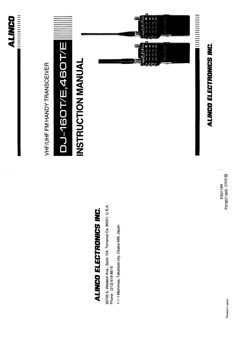
VHF/UHF
DUAL
BAND
FM
TRANSCEIVER
INSTRUCTION
MANUAL
DR-510E
ALINCO
ELECTROMICS
INC.

TABLE
OF
CONTENTS
Introduction
pg.
2
Accessories
pg.
2
Specifications
pg.
3
Operation
pg.
4
Control
Functions
pg.
4
Function
Operation
pg.8
Scan
pg.
10
Priorlty
Scan
pg.
11
Tone
Frequency
Seiection
pg.
12
Tone
Squelch
(CTGSS)
pg.
13
Repeater
Operation
pg.
13
Reverse
Function
pg.
13
Transmission
pg.
14
Installation
pg.
15
INTRODUCTION
Congratulation,
now
you
are
the
owner
of
one
of
our
many
"ALINCO"
products.
Your
DR-510T/E
has
been
manufactured
and
tested
very
carefully
at
the
factory
and
will
give
you
satisfactory
Operation
for
many
years.
ACCESSORIES
Carefully
unpack
your
transceiver
and
you
will
find
the
following
accessories
included
with
the
transceiver.
•Microphone
xl
•D.C.
Power
Cord
xl
•Spacefuse(ISA)
x2
•Installinganglejoint
xl
•M5x20
mm
Screw
x4
•M5x20
mm
Mounting
Screw
x4
•MS
Nut
x4
•MSFIatWasher
x4
•MS
Spring
Washer
x4
•ScrewsforBracket
x4
•M4x14
mm
Screw
x4
•Rubber
Support
x2
-2-

SPECiFICATIONS
■
General
Frequency
Coverage
144.0~148.0MH2(DR-510T)
440.0-450.0
MHz
144.0-146.0
MHz
(DR-510E)
430.0-440.0
MHz
Antenna
Impedance
50
ohms
unbalanced
Power
Supply
Requirement
13.8
Volts
D.C.
Current
Drain
all
3.8
V
—
Receiving
Squelched:
does
not
exceed
500
mA
Transmitting
High:
45
W
approx.
9.5
A
at
VHF
35
W
approx.
10
A
at
UHF
Lew:
5
W
approx.
4
A
at
VHF
5
W
approx.
4
A
at
UHF
Dimension
140
mm
(W)
x
50
mm
(H)
x205
mm
(D)
(5y2"x2"x8yi6")
Weight
Approx.
1.7
kgs.
(3.75
ibs.)
■
Transmitter
Output
Power
High;
45
Watts
at
VHF,
35
Watts
at
UHF
Low;
Approx.
5
Watts
at
both
bands
Emission
Mode
16F3
Modulation
System
Variable
Reactance
F.M.
Max.
Frequency
Deviation
..
±5
kHz
Spurious
Emission
More
than
60
dB
below
carrier
Microphone
Electret
Condenser
Microphone
Operating
Mode
Simplex
Duplex:
±600
kHz
from
receive
frequency
at
VHF
:
±5,1.6,7.6
MHz
from
receive
frequency
at
UHF
(Odd
Offsets
programmable)
DTMF
Encoder
Built-In
■
Recelver
Receiving
System
Superhetrodyne,
dual
conversion
Modulation
Acceptance
—
16F3
Intermediate
Frequency
Ist
10.7
MHz
2nd
455
kHz
at
VHF
Ist
30.825
MHz
2nd
455
kHz
at
UHF
Sensitivity
12
dB
SINAD
less
than
0.16
pV
Selectivity
More
than
±6
kHz
at
-6
dB
Less
than
±
12
kHz
at
-60
dB
Audio
Power
Output
More
than
1.5
Watts
(8
ohms-10%
Distortion)
Speaker
Impedance
8
ohms
-
3
-

OPERATIONI
CONTROL
FUNCTIONS
O
Front
Panel
O
0
0
o
VOl_
SOL.
o
m]
O
0
©
O
<P
0
O
Main
Dia!
Main
dial
Is
used
to
select
the
transmit/recelve
frequency,
Mem
ory
Channel,
Frequency
Step,
Tone
Frequency,
and
Offset
Frequency.
0
Display
Panel
The
LCD
displays
Operation
in-
formation
such
as
transmit/receive
frequencies,
memory
Channel
In
formation,
Offset,
tone
frequency
etc.
See
page
6
for
additional
in-
formation.
O
VOL
(Volume)
Control
Tum
the
control
clockwise
to
in-
crease
the
volume,
and
turn
it
counterclockwise
to
decrease
the
volume.
O
SQL
(Squelch)
Control
THE
SQL
control
Is
used
to
ellmln-
ate
nolse
during
no
Signal
periods.
Normally
this
control
Is
adjusted
clockwise
until
the
noise
just
dls-
appears,
and
the
BUSY
Indicator
goes
off.
(Threshold
level)
0
H/L
(High/Low)
Switch
ThIs
Switch
Is
used
to
select
the
desired
transmitter
Output
power
level.
O
Power
Switch
Press
to
turn
on.
Press
again
to
turn
off.
Function
Keys
(7
through
15)
NOTE:
Commands
underlined
Indi-
cated
In
Blue
on
transcelver
keys.
O
F
(Function)
Key
ThIs
Is
used
to
access
secondary
Controlling
function
labeied
in
blue.
i.e.
MW,
BAND
CH.SP,
LOCK,
BEEP,
SKIP,
and
CALL
W.
See
Function
Operation
pages
8-10.
MW
is
used
with
the
F
key
to
störe
data
in
memory.
See
Memory
Pages
9-10.
-
4
-

O
MHz
key
The
MHz
key
is
used
to
change
the
frequency
up
or
down
in
one
MHz
Steps.
Press
the
MHz
key,
and
the
decimal
point
and
kHz
digits
will
disappear
from
the
display.
The
frequency
in
MHz
will
be
changed
by
rotating
the
main
dial
or
pressing
the
UP/DOWN
buttons
on
the
microphone.
Press
the
MHz
key
again
or
the
PTT
Switch
to
retum
the
display
to
the
complete
frequency
readout.
BAND
is
used
with
the
F
key
to
select
VHP
or
UHF
band.
See
page
8.
o
VFO/M
(VFO/MEMORY)
key
VFO/M
is
used
to
select
VFO
or
Memory
mode.
Press
the
VFO/M
key
to
alternate
between
VFO
and
the
Memory
Channel
mode.
CH.SP
is
used
with
the
F
key
to
select
frequency
steps
for
program-
ming
and
scanning.
See
page
8.
(D
REV
(Reverse)
key
REV
is
used
to
invert
the
TX
and
RX
frequency
in
Repeater
mode.
LOCK
is
used
with
the
F
key
to
disable
the
Function
keys.
See
page
8.
(DSHIFTkey
The
SHIFT
key
is
used
to
select
the
desired
transmitter
offset
during
re
peater
or
Cross
Band
Operation.
When
the
key
is
pressed,
the
offset
mode
cycles
from
-
to
-h
to
Dual
to
Simplex.
(D
TONE
key
(DR-510E:
CTCSSkey)
The
TONE
key
is
used
to:
A.
Activate
the
Tone
frequency
selection
process.
See
page
12.
B.
Enable/Disable
the
Encode/
Decode
functions.
See
page
12.
The
BEEP
key
is
used
with
the
F
key
to
Enable/Disable
the
function
confirmation
tone.
See
page
8.
(E)
PRI
(Priority)
key
The
PRI
key
is
used
to
control
Priority
function.
See
pages
11-12.
(D
SCAN
key
The
SCAN
key
is
used
to
activate
the
frequency
scan
and
memory
Scan
functions.
See
pages
10-11.
The
SKIP
key
is
used
with
the
F
key
to
skip
busy
memory
frequencies
when
scanning.
See
page
8.
(DCALLkey
(DR-51OE:
Tone
Burst
key)
The
CALL
key
is
used
to
bring
Memory
Channel
"C"
to
the
display.
See
page
9.
The
CALL
W
is
used
to
enter
a
frequency
into
memory
Channel
"C".
See
page
9.
0
Microphone
Connector
Plug
the
microphone
into
this
jack.
DC5V
NC(|>
@UP
<DDWN
GND
(MIC)
®GND
-
5
-

UHF
Display
0
O
0
O
ri
n
_
uu
m8
000©
REV
+
-
OUAL
ENG
DEC
PRt
rCAUT
«J
33
n
ri
„
^
[Jn3TcgJ=fscW=,.yOViR
-0
T
0
O
REV
(Reverse)
Indicator
Tums
on
when
the
reverse
function
has
been
selected.
©
Shift
and
Dual
Indicators
"+"
or
indicator
turns
on
during
repeater
offset
operations.
See
page
13.
"DUAL"
indicator
tums
on
during
Dual
Operation.
See
page
14.
0
ENG
(Encoder)
indicator
Turns
on
to
indicate
that
ENCOD-
ING
TONE
function
is
active.
O
DEC
(Decoder)
indicator
Tums
on
to
indicate
ttie
DECODER
(CTCSS)
function
is
active.
0
PRI
(Priority)
Indicator
Turns
on
to
indicate
the
PRIORITY
function
is
active.
O
CALL
Indicator
Tums
on
to
indicate
the
CALL
func
tion
is
active.
O
Frequency
display
Displays
the
transmit/receive
fre
quency,
Frequency
Step,
or
Tone
Frequency.
O
Decimal
point
indicator
Separates
the
MHz,
and
kHz.
Flashes
in
Scan
mode.
Disappears
in
Memory
skip
mode.
©
BUSY
indicator
On
whenever
the
squelch
is
open
or
Signal
is
received.
©
S/RF
Meter
This
meter
indicates
the
relative
receive
input
Signal
strength
and
relative
transmitter
RF
Output.
©
ON
AIR
Indicator
Tums
on
during
transmit
opera
tions.
©
M
(Memory)
indicator
Turns
on
whenever
the
transceiver
is
in
the
Memory
mode.
Flashes
to
indicate
programming
in
process.
©
Memory
Channel
Number
display
Indicates
the
selected
memory
Channel
Number.
-6-

REAR
PANEL
O
Antenna
Connector
Used
to
connect
the
antenna
to
the
set.
Use
a
PL259
antenna-plug
with
50
Ohms
impedance.
©
Power
Connector
Connect
the
supplied
power
cable
to
this
connector.
O
External
Speaker
Jack
When
an
external
Speaker
(Imp.:
8
Ohms)
is
used,
connect
it
to
this
jack.
-
7
-

FUNCTION
Operation
Whenever
the
F
key
is
pressed,
the
"M"
indicator
will
flash.
You
must
com-
plete
Ihe
desired
programming
within
5
seconds,
or
the
"M"
indicator
will
turn
off
or
stop
flashing.
In
that
case,
you
must
press
the
F
key
again.
The
F
key
is
used
with
secondary
functions
printed
in
blue
on
the
trans-
ceiver
function
keys.
1.
VHF/UHF
Band
Selection
To
select
the
desired
band,
press
the
F
key
and
then
the
BAND
key.
Each
time
you
press
the
keys,
VHF
and
UHF
will
be
selected
alternate-
ly-
2.
Frequency
Step
Selection
The
frequency
Step
can
be
selected
by
using
the
following
procedure:
A.
Press
the
VFO/M
key
to
select
the
VFO
mode.
B.
Press
the
F
key
and
then
the
CH.SP
key.
C.
Select
the
desirea
frequency
Step
using
the
Main
Dial
or
the
microphone
UP/DOWN
but-
tons.
The
example
below
Shows
the
order,
in
which
the
Main
Dial
(or
UP/DOWN
but-
tons)
will
increase
or
decrease
the
spacing.
^
5
kHz
^
25
kHz
20
kHz
10
kHz
12.5
kHz
■15
kHz
D.
Press
the
F
key
again
or
PTT
Switch
to
return
to
VFO
mode.
3.
Key
Lock
A.
Press
the
F
key,
and
then
press
the
Lock
key
again.
B.
The
"L"
indicator
will
replace
the
Memory
number
shown
on
right
side
of
display.
C.
Stops
all
function
keys
except
the
PTT
Switch.
D.
To
cancel
this
function,
press
the
F
key
and
the
LOCK
key
again.
4.
BEEPON/OFF
A.
Press
the
F
key,
and
then
press
the
BEEP
key.
B.
Repeating
this
procedure,
beep
will
turn
ON
and
OFF
alter-
nately.
5.
Memory
Sklp
The
Memory
Channel
Skip
function
allows
you
to
temporarily
skip
un-
wanted
Memory
Channels
during
Memory
Channel
Scanning.
A.
Press
the
VFO/M
key
to
select
the
Memory
Channel
mode.
B.
Select
the
Memory
Channel
that
you
want
to
skip
using
the
Main
Dial
or
the
microphone
UP/DOWN
buttons.
Press
F
key,
and
then
press
the
SKIP
key.
The
decimal
point
between
MHz
and
kHz
will
dis-
appear
from
the
display.
C.
A
frequency
in
memory
without
the
decimal
point
will
be
skip-
ped
when
scanning
memories.
D.
To
cancel
Memory
Channel
Skip,
press
the
F
key
and
the
SKIP
key
again.
-
8
-

6.
CALL
Channel
Entry
(DR-510Tonly)
A.
Selecl
VFO
mode
by
pressing
the
VFO/M
key.
B.
Selecl
the
desired
operaling
band
and
frequency.
C.
Press
the
F
key,
and
then
press
the
CALL
W.
D.
When
the
CALL
W
is
pressed,
the
frequency
shown
on
the
LCD
will
be
stored
inte
memory
"C".
E.
Whenever
CALL
is
pressed,
Memory
"C"
will
come
to
the
dispiay.
F.
To
Change
from
CALL
mode
back
to
VFO
or
Memory,
press
the
VFO/M
key.
7.
MEMORY
A
lithium
battery
is
instaiied
to
retain
memory
in
the
transceiver.
Turning
off
the
POWER
switch,
disconnecting
power
cable,
or
a
power
failure
will
not
erase
mem
ory.
The
battery
should
fast
for
approximately
5
years.
•MIcroprocessor
Initiallzatlon
When
you
want
to
erase
all
pro-
grammed
data,
or
if
the
dispiay
should
Show
erroneous
Informa
tion,
you
should
reset
(initialize)
the
microprocessor
using
the
foi-
lowlng
procedure:
1.
Press
and
hold
the
F
key
and
the
VFO/M
key
at
same
time,
and
turn
off
the
POWER
switch.
New
turn
the
POWER
switch
on
again,
while
still
holding
buttons
depressed.
2.
Release
the
buttons—Factory
Programming
is
now
in
place.
•Memory
Channel
This
transceiver
has
14
memory
Channels
(1-9,
A-E).
In
additlon
to
serving
as
normal
memory
Channels,
some
serve
a
dual
pur-
pose.
The
functions
of
the
Mem
ory
Channels
A-D
are
described
below.
A.
Memory
Channels
A
and
B
are
used
to
störe
the
Frequen
cy
iimits
for
the
Program
Scan
Function.
For
additionai
in-
formation,
see
VHF
or
UHF
Band
Scan
on
page
11.
B.
Memory
Channel
C
is
used
to
Store
the
CALL
Channel
fre
quency.
C.
Memory
Channel
D
is
used
to
Store
the
transmit
frequency
used
for
odd
offset
Operation.
•Memory
Channel
Contents
Each
Memory
Channel
is
capable
of
sloring;
Frequency
SHIFT
Status
(Offset)
TONE
Status,
(Encode,
Decode,
and
Frequency)
Receive
Frequency
for
Dual
band
Operation.
See
page
14.
•Memory
Entry
1.
Press
the
VFO/M
key
to
select
the
VFO
mode.
2.
Select
the
desired
operating
frequency.
3.
Activate
sub
audible
tone
if
it
is
required.
4.
Press
the
F
key.
The
"M"
indicator
will
flash.
-
9
-

Select
the
desired
Memory
Channel
using
the
Main
Dia!
or
the
microphone
UP/DOWN
buttons.
Press
the
MW
key
during
the
"M"
Indicator
is
flashing.
If
the
"flashing
stops
betöre
the
MW
key
is
pressed,
you
must
press
F
key
again
in
Order
to
complete
the
desired
function.
■
SCAN
The
following
scan
options
are
avail-
able:
Program
Scan
(Limited
Frequency
Coverage
in
one
band
only)
Memory
Scan
VHF
or
UHF
Band
scan
A.
Programmable
Scan
The
scan
frequency
is
determined
by
the
frequencies
stored
in
Mem
ory
Channels
A
and
B.
The
frequency
stored
in
Memory
Channel
A
and
B
must
be
different
frequencies.
Betöre
pressing
the
SCAN
key,
adjust
the
SQL
control
to
the
threshold
level.
1.
Determine
the
desired
scan
fre
quency
ränge
and
enter
the
fre
quencies
into
Memory
Channel
A
and
B.
2.
Press
the
VFO/M
key
to
select
the
VFO
mode,
and
also
select
the
band
of
the
stored
frequen
cies.
3.
Press
the
SCAN
key
to
intitate
scan.
4.
To
clear
scanning,
press
the
SCAN
key
or
the
microphone
P.T.T.
Switch.
B.
Memory
Scan
1.
Press
the
VFO/M
key
to
select
the
Memory
Channel
mode.
2.
Betöre
pressing
the
SCAN
key,
adjust
the
SQL
control
to
the
threshold
level.
3.
Press
the
SCAN
key
to
initiate
scan.
4.
To
clear
scanning,
press
the
SCAN
key
or
the
microphone
P.T.T.
switch.
-10-

VHP
or
UHF
Band
Scan
This
Scan
will
cover
the
entlre
tun-
ing
ränge
of
VHP
or
UHF.
1.
Press
the
VFO/M
key
to
select
the
VFO
mode,
then
select
the
band,
VHF
or
UHF.
2.
Store
the
same
frequency
Into
Memory
Channels
A
and
8.
3.
Betöre
pressing
the
SCAN
key,
adjust
the
SQL
control
to
the
threshold
level.
4.
Press
the
SCAN
key
to
Initiate
Scan.
5.
To
clear
scanning,
press
the
SCAN
key
or
the
microphone
P.T.T.
Switch.
•The
transceiver
will
stop
on
a
busy
Channel
until
the
Signal
drops.
After
a
Short
delay
the
scan
will
resume.
•If
you
want
to
resume
scanning
when
the
transceiver
stops
on
a
busy
Channel,
rotate
the
Main
Dial
or
press
the
microphone
UP/
DOWN
buttons.
■
PRIORITYSCAN
The
following
Priority
Scan
options
are
available:
Memory
Priority
Scan
VFO
Priority
Scan
CALL
Priority
Scan
A.
Memory
Priority
Scan
1.
Store
the
desired
priority
fre
quency
into
any
Memory.
2.
Select
VFO
mode,
and
dial
up
the
frequency
you
want
to
oper-
ate
on.
3.
Press
the
PRI
key
to
initiate
Memory
Priority
Scan.
The
transceiver
will
scan
the
Priority
in
Memory
for
1
second
out
of
6
seconds
and
the
VFO
frequency
for
the
remaining
5
seconds.
4.
When
a
Signal
is
present
on
the
Priority
Memory
Channel,
press
the
PRI
key,
and
then
press
the
VFO/M
key.
The
Priority
scan
will
stop
and
the
Memory
Chan
nel
will
come
to
the
display.
B.
VFO
Priority
Scan
This
function
is
the
reverse
of
Mem
ory
Priority
Scan.
1.
Select
VFO
mode,
and
dial
up
the
frequency
to
be
scanned.
2.
Select
the
desired
Memory
you
want
to
operate
on.
3.
Press
the
PRI
key
to
initiate
VFO
Priority
Scan.
4.
To
cancel
this
scan,
press
the
PRI
key
again.
-11-

C.
CALL
PRIORITY
SCAN
1.
Store
the
desired
frequency
for
Operation
in
Memory
Channel
"C".
2.
Press
the
CALL
key
and
then
the
PRI
key.
3.
The
tranceiver
will
scan
the
VFO
for
1
second
and
the
CALL
Channel
for
5
seconds
alter-
nately.
TONE
FREQUENCY
SELECTION
To
select
a
Tone
(CTCSS)
Frequen
cy,
press
the
VFO/M
key
and
select
the
VFO
mode,
then
press
the
TONE
key.
The
display
will
indicate
a
Tone
Frequency
in
Hz.
Select
the
desired
Tone
Frequency
using
the
microphone
UP/DOWN
buttons
or
the
Main
Dial.
There
are
37
CTCSS
Tone
Fre-
quencies
available
as
shown
below.
Press
any
key
or
the
microphone
PTT
Switch
to
retum
to
the
receiver
frequency
display.
The
subaudible
tone
will
be
transmitted
whenever
the
PTT
switch
is
depressed.
Subaudible
Tone
Chart
Hz
Hz
Hz
Hz
Hz
Hz
67.0
85.4
107.2
131.8
162.2
203.5
71.9
88.5
110.9
136.5
167.9
210.7
74.4
91.5
114.8
141.3
173.8
218.1
77.0
94.8
118.8
146.2
179.9
225.7
79.7
100.0 123.0
151.4
186.2
233.6
82.5
103.5
127.3
156.7
192.8
241.8
250.3
-12-

■
TONE
SQUELCH
(CTCSS)
This
function
allows
you
to
remain
squelched
until
the
proper
Tone
Fre-
quency
is
received.
If
you
are
on
a
busy
frequency,
this
can
be
quite
an
ald.
1.
Press
the
TONE
key.
The
"ENG"
will
appear
on
the
display
panel.
Press
the
TONE
key
again.
The
"DEC"
will
appear
next
to
the
"ENG".
2.
Your
radio
will
now
remain
squel
ched
until
the
proper
code
is
re
ceived.
You
should
ensure
all
stations,
you
wish
to
communicate
with,
use
the
same
Tone
Frequency.
3.
To
release
the
Tone
Squelch
func
tion
(Normal
noise
activate
squelch),
press
the
TONE
key
again.
The
"ENG"
and
"DEG"
will
disappear
from
the
display.
(DR-510E:
Option)
■
REPEATER
Operation
All
amateur
radio
repeaters
utilize
a
separate
receiver
and
transmitter
sec-
tion.
The
receiver
frequency
may
be
either
above
or
below
the
transmitter
frequency.
This
transceiver
allows
you
to
störe
the
frequency.
offset
frequency
(0.6,
1.6,5.0
and
7.6
MHz.)
and
offset
direc-
tion
in
Memory
Ghannel
(1-9
and
A-E).
To
select
the
desired
transmitter
offset
direction,
press
the
SHIFT
key.
Each
time
you
press
the
key,
the
radio
will
advance
from
one
offset
to
the
other,
i.e.
to
"+"
to
"Dual".
To
select
the
desired
transmitter
offset,
press
the
SHIFT
key,
and
then
rotate
the
Main
Dial
or
depress
UP/DOWN
button
on
the
microphone.
Each
time
you
rotate
or
depress
these
controls,
the
radio
will
advance
through
the
following
steps:
"0"
to
"0.6"
to
"1.6"
to
"5"
to
"7.6"
in
MHz.
After
the
offset
has
been
stored,
press
any
key,
except
the
SHIFT
key,
or
depress
the
PTT
switch.
The
normal
display
will
return.
■
REVERSE
Function
The
REV
key
has
been
provided
to
allow
you
to
reverse
the
transmit
and
receive
frequencies.
To
use
the
Re
verse
function,
press
the
REV
key.
The
REV
indicator
will
light
in
the
display
to
remind
you
that
you
are
working
a
reverse
repeater
pair.
To
return
to
normal
Operation,
press
the
REV
key
again.
-13-

TRANSMISSION
Caution
1.
Ensure
that
an
antenna
with
a
low
Standing
wave
ratio
(SWR)
is
attached
to
the
antenna
connector
before
attempting
to
transmit.
Fail-
ure
to
provide
proper
terminatlon
may
result
in
damage
to
the
final
ampiifier
section.
2.
Always
check
to
ensure
the
fre-
quency
is
clear
before
transmitting.
A.
Simplex
Operation
1/2
Dupiex
(Repeater)
Operation
1.
Select
the
desired
band
(VHF,
UHF).
2.
Select
the
desired
operating
fre-
quency
using
any
of
the
methods
described
above.
3.
Press
the
microphone
PTT
switch.
The
ON
AIR
indicator
will
light.
4.
Speak
into
the
microphone.
The
recommended
distance
to
the
mi
crophone
is
2
inches
(5
cm).
Talking
too
far
away
may
result
in
reports
of
weak
audio.
5.
Release
the
microphone
PTT
switch
to
return
to
the
receive
mode.
The
ON
AIR
indicator
should
go
out.
B.
Duai
Operation
(Fuii
Dupiex)
1.
Select
the
desired
transmit
fre-
quency.
2.
Press
the
F
key
and
select
the
Memory
"d".
3.
Press
the
F
key
and
the
MW
key
to
Store
the
transmit
frequency
into
the
Memory
"d".
4.
Press
the
F
key
and
the
BAND
key
to
change
to
other
band.
5.
Select
the
receive
freqency
by
the
usual
means.
6.
Press
the
SHIFT
key
to
select
the
DUAL
on
the
display.
7.
Key
the
PTT
switch
and
you
will
transmit
on
one
band
while
simul-
taneously
receive
the
other
band—
Füll
Dupiex
Cross
Band.
-14-

INSTALLATION
■
MOBILE
INSTALLATION
1.
Location
The
transceiver
may
be
instalied
in
any
position
in
your
car,
where
the
controis
and
microphone
are
easily
accessible
and
safe
Operation
of
the
vehicie
or
the
Performance
of
the
set
will
not
be
interfered
with.
Refer
to
the
diagrams
for
installation
of
the
Mounting
Bracket:
Car
body
Mounting
screw/washer
Mounting
screw/ring
Power
Requlrements
The
transceiver
can
be
operated
from
any
regulated
12
or
13.8
V
negative
ground
source.
For
mobile
use,
power
connections
should
be
made
directiy
to
the
bat-
tery
to
minimize
the
possible
ignition
noise
pickup.
P
DG
lead
Coaxial
cable
■
BASE
STATION
INSTALLATION
For
fixed
base
Operation,
a
13.8
V
D.O.
Power
Supply
capable
of
providi'ng
at
least
15
A
continuously
is
required.
Connect
the
red
lead
of
the
power
cable
to
the
Positive
(+)
terminal,
and
the
black
lead
to
the
Negative
(-)
terminal
of
the
D.O.
Power
Supply.
-15-

ALUmO
ELECTROMICS
IND.
20705
S.
Western
Ave.,
Suite
104,
Torrance
Ca.
90501,
U.S.A.
Phone;
(213)618-8616
1-1-1
Mishimae,
Takatsuki
cIty,
Osaka
569.
Japan
PS0105
F0289G0-2000<S)
Other manuals for DR-510T
4
This manual suits for next models
1
Table of contents
Other Alinco Transceiver manuals

Alinco
Alinco DJ-A11 User manual

Alinco
Alinco DJ-G5T/E User manual

Alinco
Alinco DR-570T User manual

Alinco
Alinco DJ-162TD User manual

Alinco
Alinco F1-T Guide

Alinco
Alinco DR-CS25 User manual

Alinco
Alinco DX-10 User manual

Alinco
Alinco DR-130T User manual

Alinco
Alinco DX-801 User manual

Alinco
Alinco DR-570T/E User manual

Alinco
Alinco DJ-500T User manual

Alinco
Alinco DX-701 User manual
Alinco
Alinco DR-M06T Guide

Alinco
Alinco DR-M03 User manual

Alinco
Alinco DX-SR8 User manual

Alinco
Alinco DJ-180T User manual

Alinco
Alinco DJ-F1T User manual

Alinco
Alinco DJ-AXD4 User manual

Alinco
Alinco DJ-195 User manual

Alinco
Alinco DJ-V5T/E User manual