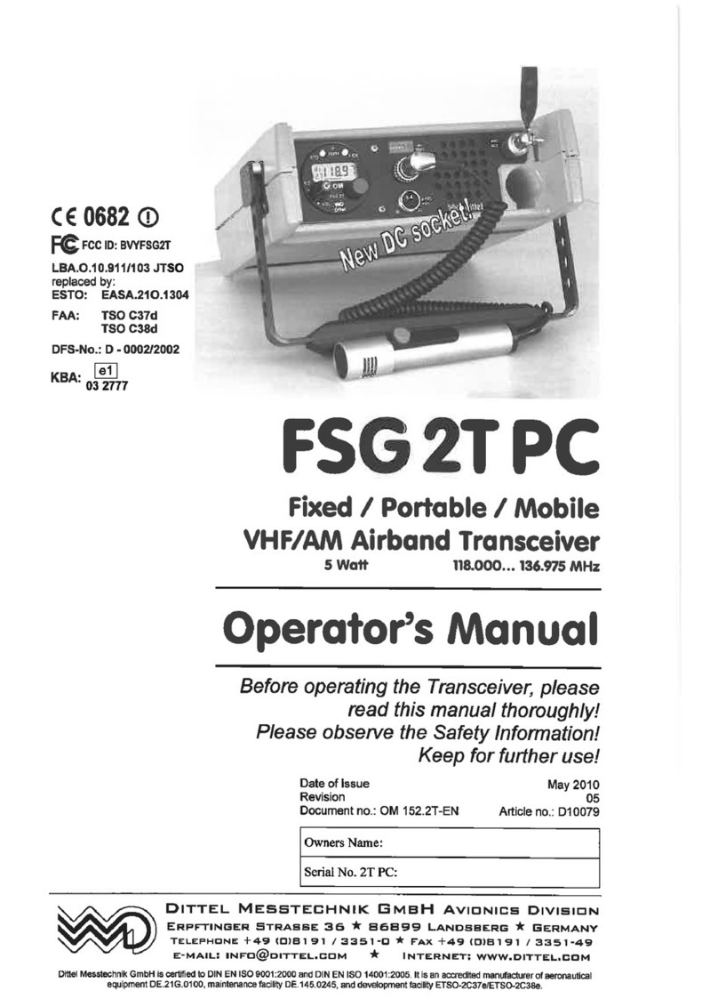
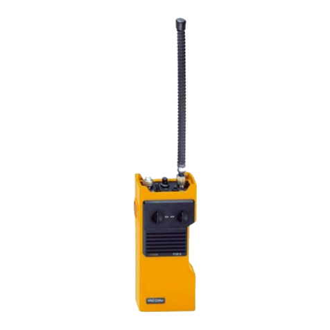
Dittel 7016 User manual

FSG 7016
WATER- and DUSTPROOF
HANDHELD UHF/AM
TRANSCEIVER
incl. VOX FUNCTION
Operator's Manual
applies for FSG 7016, article no F10165
Before operating the Transceiver, please
read this manual thoroughly!
Please observe the Safety Information!
Keep for future use!
Document No. OM 030/1.00-E
Article No. D10011
Revision No. 7
Date of Issue November 2009
Dittel Messtechnik GmbH Avionics Division
Erpftinger Straße 36 86899 Landsberg Germany
Telephone +49 (0)8191 / 3351-0 Fax +49 (0)8191 / 3351-49
Dittel Messtechnik GmbH is certified to DIN EN ISO 9001:2000 and DIN EN ISO 14001:2005. It is an accredited manufacturer of aeronautical
equipment DE.21G.0100, maintenance facility DE.145.0245, and development facility ETSO-2C37e/ETSO-2C38e.

FSG 7016
Operator’s Manual
2 D10011 November 2009
Warranty - Copyright - Service
Warranty
The details and data in this operator's manual correspond to the respective
state of technology on the day of printing. We reserve our right to change
without prior notice due to new technological design or corresponding new
production technology.
Dittel Messtechnik GmbH takes no guarantee for these documents with
respect to application and interpretation.
Dittel Messtechnik GmbH ("Warrantor") warrants to the purchaser of new radio
equipment of the warrantor's manufacture that such equipment shall be free
from defects in material and workmanship from the date of delivery.
Equipment and accessory items not manufactured by the Warrantor carry the
standard warranty of the manufacturer thereof.
This warranty does not cover equipment which has been
1. damaged or not maintained as reasonable and necessary,
2. modified in any way,
3. improperly installed,
4. repaired by someone other than the warrantor or an authorised
warranty avionics workshop, or
5. used in a manner or purpose for which the equipment was not
intended.
This warranty shall not extend to incidental or consequential damages arising
from operation of the equipment or from any claimed breach of this warranty.
Copyright 2009 Dittel Messtechnik GmbH
All rights reserved. This document contains proprietary information and such
information may not be disclosed to others for any purpose nor used for
manufacturing purposes without prior written permission of the manufacturer
Dittel Messtechnik GmbH, 86899 Landsberg, Germany.
In this document no mention is made of patents, trademark rights, or other
proprietary rights which may attach to certain words or entries. The absence of
such mention, however, in no way implies that the words or entries in question
are exempt from such rights.
Service Information
Should any unusual problem arise or further information be desired, please
contact your nearest DITTEL representative or the Dittel Messtechnik GmbH,
Avionics Department, Erpftinger Strasse 36, 86899 Landsberg, Germany.
The information in this Operator's Manual does not profess to include all the details of design,
production, or variation of the equipment, or to cover all the possible contingencies which may
arise during operation or maintenance. We welcome your comments concerning this Manual.
Although every effort has been made to keep it free of errors, some may occur. When reporting
a specific problem, please describe it briefly and include the Operator's Manual article number,
paragraph or figure number, and the page number.
Send your comments to Publications Department
Dittel Messtechnik GmbH
Erpftinger Strasse 36
86899 Landsberg am Lech
Germany
Subject to technical changes Printed in Germany

FSG 7016
Operator’s Manual
November 2009 D10011 3
Table of Contents
Paragraph Page
Warranty - Copyright - Service ........................................................................................................ 2
Table of Contents................................................................................................................................... 3
Abbreviations and Acronyms ............................................................................................................4
SAFETY INFORMATION.......................................................................................................................... 5
Section 1, General Description.......................................................................................................... 7
1.1 Introduction..................................................................................................................... 7
1.2 Equipment Description ................................................................................................... 7
1.2.1 Sophisticated Programming ....................................................................................... 7
1.2.2 Modes of Operation.................................................................................................... 8
1.3 License Requirement ..................................................................................................... 9
1.4 Equipment Supplied ....................................................................................................... 9
1.5 Optional Equipment / Spares ......................................................................................... 9
Section 2, Charging and Battery Test ........................................................................................... 11
2.1 Battery Information ....................................................................................................... 11
2.2 Battery Replacement.................................................................................................... 11
2.3 Recharging the Battery using DL-5A/7016 Drop-in Charger......................................... 12
2.4 Battery Test .................................................................................................................. 13
Section 3, Windows Programming using Programming Software V2.0 ..........................15
3.1 Introduction................................................................................................................... 15
3.2 Hard- and Software Requirements............................................................................... 15
3.3 Installation Procedure................................................................................................... 15
3.4 Control Window Command Information Instruction...................................................... 17
3.5 Edit individual settings temporarily ............................................................................... 18
3.6 Programming the new Setting(s).................................................................................. 18
3.7 Finishing the Reprogramming ...................................................................................... 18
Section 4, Operating Instructions...................................................................................................19
4.1 Introduction................................................................................................................... 19
4.2 Operator's Switches, Controls and Indicators .............................................................. 19
4.3 Preparation for Use ...................................................................................................... 22
4.4 Operation in the Receive (Listen) Mode....................................................................... 23
4.5 Operation in the Transmit (Talk) Mode......................................................................... 24
4.6 Matching an External Microphone................................................................................ 25
4.7 Operation using a Headset or Helmet .......................................................................... 26
4.8 Voice Controlled Transmit Operation (VOX) ................................................................ 27
4.9 Switching OFF.............................................................................................................. 27
4.10 Siting ............................................................................................................................ 28
4.11 Functional Checks........................................................................................................ 28
Section 5, Technical Summary of Transceiver FSG 7016 .......................................................29
5.1 Leading Particulars....................................................................................................... 29
5.2 Transmitter Characteristics: ......................................................................................... 29
5.3 Receiver Characteristics: ............................................................................................. 30
5.4 Physical and Environmental Data: ............................................................................... 30
Certificates ...........................................................................................................................................31

FSG 7016
Operator’s Manual
4 D10011 November 2009
Abbreviations and Acronyms
A/C Aircraft
A/N Article Number (Dittel
Messtechnik GmbH)
AGC Automatic Gain Control
Ah Ampere hour
AM Amplitude Modulation
ANT Antenna
Ass'y Assembly
AWG American Wire Gauge
ccw Counterclockwise (turn left ↺)
CH Channel
cont'd Continued
CTS Ready-to-Transmit
cw Clockwise (turn right ↻)
dB Decibel
dia. Diameter
EMF Electromotive Force (voltage of
an open circuit)
F/CH Frequency/Channel
FL Flight Level
g Acceleration due to gravity
GHz Gigahertz (1,000,000,000 Hz)
GND Ground
HI High Power
Hz Hertz
IF Intermediate Frequency
kHz Kilohertz (1,000 Hz)
LCD Liquid Crystal Display
LED Light Emitting Diode
LO Low Power
LOS Line-Of-Sight
m Modulation
mA Milliamperes (1/1000 A)
MD Mode
MHz Megahertz (1,000,000 Hz)
MIC Microphone
ms Millisecond (1/1000 sec)
mW Milliwatt (10-3 W)
NM Nautical miles (1.852 km)
nW Nanowatt (10-9 W)
PEP Peak Envelope Power
PLL Phase-Locked Loop
ppm Parts per million
PTT Push-To-Talk
pW Picowatt (10-12 W)
PWR Power
RF Radio Frequency
rms Effective value
(root mean square)
RTS Invitation to send
RX Receive
RxD Receive data
S+N/N Signal-to-Noise Ratio
SINAD Ratio: Signal noise distortion
noise distortion
++
+
SPKR Loudspeaker
SQ Squelch
STBY Standby
STO Store
SWR Standing-Wave Ratio
TOT Time-Out-Timer
TX Transmit
TxD Transmit data
UHF Ultra-High Frequency
VCO Voltage-Controlled Oscillator
Vdc Volts, direct current
VHF Very-High Frequency
VOL Volume
VSWR Voltage Standing-Wave Ratio
W Watt
Ohm
°C Degrees Centigrade
°F Degrees Fahrenheit

FSG 7016
Operator’s Manual
November 2009 5
SAFETY INFORMATION
Every radio, when transmitting, radiates energy into the atmosphere that may, under certain
conditions, cause the generation of sparks. All users of our UHF/AM Transceiver FSG 7016
should be aware of the following warning:
+++ Do not operate this radio in an explosive atmosphere +++
(gas, petroleum fuels, solvents, dust, etc.)!
During normal use, the radio will subject you to radio energy substantially below the level where
any kind of harm is reported.
TO ENSURE PERSONAL SAFETY, please observe the following simple rules:
•Only persons entitled may operate the UHF/AM Transceiver FSG 7016!
•DO NOT transmit when the helical antenna is very close to, or touching, exposed parts of the
body, especially the face and eyes.
•DO NOT transmit in closed vehicles, aircraft or inside buildings with the helical antenna! This
may trigger the airbag, cause malfunction of the avionics or confuse other electronic
equipment! Always operate the radio on a suitable outside / external antenna! Assure
appropriate lightning protection where an elevated outdoor antenna is used.
•DO NOT transmit on a busy channel!
•DO NOT press and hold the transmit (PTT) key when not actually desiring to transmit.
•DO NOT allow children to play with any radio equipment containing a transmitter.
•DO NOT operate the radio whilst driving. It should also be noticed that the use of a hand held
microphone while driving could constitute an offence under the Road Traffic Regulations in
certain countries.
•Always turn OFF the radio when replacing the battery pack.
•The UHF/AM Transceiver FSG 7016 may be used exclusively for communication on the
UHF/AM airband frequencies.
•Unauthorised modifications and changes of the system are forbidden!
•When replacing defective parts use only original parts or parts recommended by the
manufacturer.
•In order to prevent corrosion, the radio should be rinsed with tap-water after use in sea-
water. Wipe dry using a clean, lint-free cloth.
Nickel-metal hydride Batteries Handling Precaution
•Never dispose Ni-MH batteries in a fire or expose to high temperatures.
•Do not connect the positive (+) and negative (-) terminals of Ni-MH batteries together with
electrically conductive material, including lead wires.
•Do not transport or store Ni-MH batteries with their uncovered terminals.
•Do not strike or drop Ni-MH batteries. Sharp impacts or concussion to batteries may result in
leakage, heat generation and bursting.
•Never disassemble, modify or reconstruct Ni-MH battery packs.
•Ni-MH batteries contain a strong colourless alkali liquid. The alkali is extremely corrosive and
will cause skin damage. If any liquid from a Ni-MH battery comes in contact with a user's
eyes, they should immediately flush their eyes with clean water enough and consult a doctor.
The strong alkali can damage eyes and lead to permanent loss of eyesight.
Ni-MH
This radio contains a Ni-MH battery!
•DO NOT dispose worn out Ni-MH batteries with domestic waste.
•Consumers are obliged by law to return Ni-MH batteries at the end of their
service lives to the public collecting points set up for this purpose or point of
sale.

FSG 7016
Operator’s Manual
6 D10011 November 2009
THIS PAGE
INTENTIONALLY
LEFT BLANK

FSG 7016
1 General Description
November 2009 7
Section 1 General Description
1.1 Introduction
This Operator's Manual contains information relative to the physical, mechanical
and electrical characteristics of the Dittel Messtechnik GmbH FSG 7016 handheld
water- and dustproof UHF/AM Communications Transceiver with VOX controlled
transmit.
This excellent transceiver system FSG 7016, article no F10165, manufactured by
Dittel Messtechnik GmbH, 86899 Landsberg am Lech, Germany, is a
microprocessor controlled, high performance, 16-channels pre-set, handheld
UHF/AM air band transceiver, complete with rechargeable, snap-on battery pack,
helical antenna and removable, adjustable carrying strap on the radio's rear side.
Every unit leaves our factory only after extensive tests.
1.2 Equipment Description
This light weight, small size, splash and dust proof transceiver offers universal
operation on up to 16 fixed, software pre-programmed channels at 25 kHz spacing
out of 7,000 channels within the full UHF/AM 225.000 MHz to 399.975 MHz
frequency range. The rechargeable 1,500 mAh high capacity Ni-MH battery,
together with three programmable RF output levels plus 'receive only' mode on any
channel, allow very flexible operations.
The operating mode is Simplex, i.e. transmitting or receiving only in turns.
Excellent collocation characteristics - especially the very high receiver sensitivity -
allow universal, flexible and reliable line of sight voice radio communications also in
difficult environment. Due to a built-in voice controlled communication function
(VOX) -transmitting without pressing any PTT key - both hands get therefore free
for other jobs. Very long battery operating times are available for independent hand
portable, body worn, and mobile use, and even for long distance fixed base
operations, where a wide band roof top external antenna (antistatic grounded) is
used.
Battery replacement or discharge does not result in loss of memory information.
A comprehensive manually or automatically activated acoustic and LED battery
status control, besides the high level transmit side tone, gives the operator easy to
understand battery status information, most useful at difficult missions. This is
especially helpful in extreme operating conditions, e.g. as helicopter winch men or
for parachute missions.
The audio volume is adjustable in seven steps to control receive, transmit side
tone, and battery status/warning beep tones.
External microphone sensitivity can be easily set in seven steps.
Both - the built-in microphone and internal loudspeaker - are switched OFF, when
an external microphone is connected to the multifunction 10-pole accessory socket.
Together with a wide range of accessories, this high performance light weight
handy UHF/AM radio is especially suitable for reliable use also under extremely
difficult environmental operating conditions.
1.2.1 Sophisticated Programming
Easy interfacing through the 10-pole accessory socket, using a special DITTEL
adapter cable to any standard Personal Computer running WINDOWS 98, NT,
2000 or XP, allows simple and quick control, selection, and reprogramming on any
of the 16 memory channels. Any combination of frequency and / or RF output
power selection / programming is possible.

FSG 7016
1 General Description
8 D10011 November 2009
1.2.2 Modes of Operation
The transceiver may be operated in two main modes - transmit or receive - as
selected by the transmit (PTT) key or an external microphone of the transceiver:
TRANSMIT MODE (STANDARD) - When the built-in or accessory PTT key is
pressed and held, the transceiver will operate in the transmit mode.
TRANSMIT MODE (VOX operation) - When talking into an external microphone
(e.g. throat microphone), the transceiver will operate in the transmit mode.
Transmission is monitored by a sidetone signal applied to the phone.
The 'TX BATT' LED will light red, indicating that the transmitter is activated. A five
minute transmit time out timer is used to limit the duration of calls and to guard
against accidental PTT locking on the transmitter and tying up the radio system.
Transmission will occur on one of the 16 pre-programmed channel frequencies
(any frequency out of 7,000 channels) with an pre-programmed output power level,
determined by the setting of the 'CH' switch.
RECEIVE MODE - When the built-in or accessory PTT key is released, or during
VOX-Mode talking into the external microphone stops, the transceiver will operate
in the receive mode. The 'TX BATT' red LED will go OFF, indicating that the
transmitter is de-activated. Reception on one of the 16 pre-programmed channel
frequencies, as selected by the 'CH' switch, will occur. The setting of the 'VOL'
control determines the audio level produced from the internal loudspeaker and/or
the external headphone. When the 'VOL' control is adjusted in the clockwise
direction, the audio level will increase.
IMPORTANT!
•For VOX or other operating conditions, an external helmet or
headset microphone have to be connected to the 'EXT' accessory
socket of the transceiver.
•In this case, either the built-in PTT key, the PTT key of an external
equipment, or the voice level (VOX) operates the transceiver.
•When the connector of an external microphone or headset
microphone is connected to the transceiver 'EXT' accessory socket,
the FSG 7016 loudspeaker and microphone are disabled and the
'VOL' control will adjust the audio level applied to the external
speaker or headphone, as applicable.
•When operating the FSG 7016 together with a speaker/microphone
A/N F10168, the FSG 7016 speaker is disabled during receive. When
pressing the PTT key at the speaker/microphone, the FSG 7016
microphone will be disabled!
•Connection of only a headphone (without microphone) does not
disable the FSG 7016 built-in microphone and loudspeaker.

FSG 7016
1 General Description
November 2009 9
1.3 License Requirement
IMPORTANT!
•This UHF/AM equipment always requires an individual operating
license. Depending on national regulations, such license must be
applied for at appropriate National Authorities, using suitable
application forms.
•Your DITTEL representative can assist you in filing the appropriate
documents and will program each radio with your authorised
frequencies, operating modes TX/RX or RX only, for each of the 16
channels.
1.4 Equipment Supplied
UHF/AM hand-held airband Transceiver FSG 7016, 16 pre-
programmed channels (factory pre-set or on customer's order)
out of 7,000 channels (E58154); including one 1.5 Ah battery
pack (E58155), helical antenna (E55275), hand-holder (E55383)
and Operator's Manual, ready for use.
Article Number
F10165
1.5 Optional Equipment / Spares
Various audio, control, antenna, and charger accessories allow mobile flight co-
ordination and many other demanding applications, besides even specialised
operations, like airfield, Search And Rescue, parachute, helicopter winch man, fire
fighting, Naval air and/or Army air mission use, etc.
10-pole accessory connector, twist lock, sealed,
to connect customer’s accessories to FSG 7016,......................................F10172
Spare wideband helical antenna, 225 … 400 MHz,
high omni-directional efficiency, TNC connector ..................................... E55275
TNC antenna coaxial cable connector, solder type ................................. E08976
DL-5A/7016 drop-in automatic 10 hr. automatic desktop Ni-MH charger,
115/230 VAC, temperature controlled, autoswitching to trickle rate.........F10167
Spare Ni-MH battery 12 Vdc/1,500 mAh, protected, sealed.................... E58155
Hand-holder complete, with adjustable strap, hook and loop fastener.... E55383
Spare adjustable strap, black, hook and loop fastener............................ E55997
Speaker/Microphone, fist type, coiled cord, rain proof,
10-pole plug ..............................................................................................F10168
External inline PTT key U-94 A/U, coiled cord, 10-pole plug....................F10170
FSG_PROG control software for PC computer, CD-ROM .......................F10173
Interface cable to PC computer (RS-232) COM1 or COM2,
10-pole to 25-p female, adapter 25-p male/9-p female.............................F10166
Set of Adapters, to perform pressure test ................................................F10187

FSG 7016
1 General Description
10 D10011 November 2009
THIS PAGE
INTENTIONALLY
LEFT BLANK

FSG 7016
2 Charging and Battery Tes
t
November 2009 11
Section 2 Charging and Battery Test
2.1 Battery Information
The snap-on type battery pack of the radio FSG 7016 contains ten top quality
rechargeable Ni-MH batteries with a capacity of 1,500 mAh. They provide sufficient
electrical DC power to supply the radio and other connected special accessory.
To maintain the battery performance and its cycle service life, the following should
be noticed:
•Self-discharge of batteries when not in use (battery pack separated from radio)
is usual and permitted (maximum storage time one year at room temperature).
•When storing the radio without recharging for a period longer than 3 to 4 month,
detach/separate the Ni-MH battery pack from FSG 7016 radio.
•To prevent Ni-MH batteries from losing capacity, they should be fully discharged
and charged cyclically, at least once a month (avoids memory effect).
•Use only DITTEL Ni-MH battery chargers, otherwise you risk to lose the 24
month warranty as well as battery performance/reliability.
2.2 Battery Replacement
CAUTION!
•When removing or replacing the battery pack, the radio must be
turned OFF.
•Hold the radio with one hand and the battery pack with the other. Press the
locking tab
13
on the left side of the transceiver's case. The battery pack swings
open and can be removed.
•To reinstall the battery pack, hold it with the groove (type plate) on the left side.
Hinge battery nose into recess on the right side of radio and give a push until
locking tab will click, locking the battery pack in position. Check for proper seat.
•Rechargeable DITTEL battery packs can be charged separately or while
attached to the radio.
•Periodically check the contacts on the bottom of battery pack for dirt that may
prevent a good electrical contact with the charging base.
•Do not dispose of a battery pack in fire. An explosion may occur.
NEVER throw any worn out batteries into domestic waste.
You must return it for recycling!

FSG 7016
2 Charging and Battery Test
12 D10011 November 2009
2.3 Recharging the Battery using DL-5A/7016 drop-in Charger
1
2
3
The drop-in charger DL-5A/7016 is designed for
connecting to 115 VAC or 230 VAC, 50 to 60 Hz mains.
First of all, check that the charger's operating voltage
is identical with your local mains supply. If required, set
the voltage selector switch 3by means of a suitable
tool to the respective voltage, changing of fuses is not
required. DL-5A/7016 is factory set to 230 VAC!
Plug the mains cable into a suitable wall outlet. The red
pilot lamp 1lights up.
For charging, insert the complete hand-held UHF
Transceiver FSG 7016 or only the removed Ni-MH
battery pack upright into the charging chamber in such
a way, that the recess on the battery case matches with
the nose in the chamber.
If the battery is discharged, the charger switches
immediately to rapid charge (yellow lamp 2lights up).
Rapid charge - yellow pilot lamp 2 lights
The duration of charge depends on the state of the battery and is approx. 8 hours
(for 1.5 Ah battery). When the switch-off voltage is reached the charger switches
automatically to trickle charge. The capacity at the end of rapid charging is about
90% of the full rated capacity.
Trickle charge - yellow pilot lamp 2 goes off
The Ni-MH battery pack is now continuously charged on low current. The full
capacity of the battery is thus guaranteed. Overcharging the battery is not possible
due to automatic and temperature controlled charging function, even if the trickle
charge is maintained over a long period.
Batteries in chargers operating on trickle charge are fully charged.
IMPORTANT!
•With drop-in charger DL-5A/7016 (article no. F10167) 12 Vdc/1.5 Ah
battery packs of the FSG 7016 can be recharged.
•To prevent fire or shock hazard, do not expose the unit to rain or
moisture.
•To avoid electrical shock, do not open the cabinet. Refer repairing to
qualified personnel only.
•The chargers must not be operated on or near heaters or in direct
sunlight.
•Charging should be done within the ambient temperature range of
10°C to +40°C, otherwise the battery may not be fully charged.
•The UHF Transceiver FSG 7016 with attached battery pack may be
operated while being inserted into the drop-in charger, e.g. for
temporary fixed base use.
•If a fully charged battery is removed briefly from the charger and
then reinserted the charging cycle starts again from the beginning:
brief rapid charging (yellow LED lights) followed by trickle charge.
The Ni-MH battery incurs no damage.
•If the battery is flat it is first recharged on trickle charge until its
terminal voltage reaches a certain limit where rapid charging
switches on automatically.

FSG 7016
2 Charging and Battery Tes
t
November 2009 13
2.4 Battery Test
The battery status should be checked repeatedly/frequently after battery
replacement and/or before important missions begin.
IMPORTANT!
•This is the most efficient battery capacity status test
•Do not perform the battery test on a busy channel!
Disconnect charger or remove radio from drop-in charger before testing, if
applicable.
Turn the power ON by rotating the OFF-ON-SQ OFF-VOX knob
1
clockwise from
'OFF' in the 'ON' position.
Press and hold the
smaller side TEST key
9
.
A combination of receiver noise and battery status
tones is audible via the built-in speaker or headphone.
The volume is adjustable with the VOL knob.
Simultaneously the 'TX BATT' LED
2
will flash RED in
the sequence of the battery status tone.
Battery status tone sequences and flashing of the 'TX BATT' LED
2
:
•••••••••
Three-dots sequence
=Battery is fully charged, normal battery status to use
the FSG 7016.
••••••
Two-Dots sequence
=Battery is approximately half charged. Consider to
use another, fully charged battery, or be aware of only
a limited transceiver operating time available.
•••
One-dot sequence
=Battery is discharged. Only short operating time left.
Immediate battery replacement is recommended.
Arrange for battery recharging. If possible, start a com-
plete discharge/charge cycle in order to keep the
battery fully alive for reliable, maximum life time.
NOTICE:
The one-dot sequence in transmit mode starts auto-
matically (without pressing the side TEST key), as a
warning.
____________
Continuous
=In Transmit mode, tone and red LED are 'ON'
continuously. Transmitter is now disabled due to low
supply. Receiving may still be possible but only for a
short while. REPLACE AGAINST A FULLY
CHARGED BATTERY.
____________
Continuous
=In Receive mode, the automatic continuous warning
starts a few minutes before the radio switches OFF
itself automatically due to low battery supply voltage.
Release the side TEST key
9
. Continue to program frequencies and TX power
output of the transceiver FSG 7016.

FSG 7016
2 Charging and Battery Test
14 D10011 November 2009
THIS PAGE
INTENTIONALLY
LEFT BLANK

FSG 7016
3 Programming
November 2009 15
Section 3 Programming using Software V2.0 (A/N F10173)
3.1 Introduction
IMPORTANT!
•Each radio FSG 7016 leaves the factory with frequencies and RF
output power programmed for testing purposes. Therefore it is
absolutely necessary to program your radio first before using.
3.2 Hard- and Software Requirements
To use our FSG7016 Programming Centre Software the following hardware is
required:
•a standard PC with Intel or AMD Processor running WINDOWS 98, NT, 2000 or
XP,
•an available serial port (RS-232),
•a CD-ROM drive,
•Interface cable to PC computer (RS-232), Article No. F10166
•FSG7016 Programming Centre Software, CD-ROM, Article No. F10173
3.3 Installation Procedure
•Create a directory, e.g. C:\programs\fsg7016.
•Unzip the file FSG7016.zip from CD-ROM into this directory (using e.g. WinZip).
•Create a link (contains the associated WD icon) or the desktop.
•Connect DITTEL interface cable F10166 to your computer’s COM port to be
used, and to FSG 7016 10-pole accessory socket.
•Make sure the battery pack of the radio is charged (refer to paragraph 2.4,
Battery Test).
•Switch ON the FSG 7016 radio.
•Double click on "FSG7016.exe", or on the desktop icon to start the program.
Note:
•The program is ex factory pre-set to use COM 1.
•Should COM 2 or COM 3 or COM 4 to be used, this COM 1 pre-setting may be
changed after the initial “No FSG connection” warning window appears:
•Click “OK” to confirm, this will bring-up the next warning window: “No connection
to an FSG 7016; Repeat?”
•To confirm click “Nein/No”. This closes this window.
•Select the new COM port through the menu steps “Settings” and
“Communication”, then select the correct COM port, confirm with “OK”.

FSG 7016
3 Programming
16 D10011 November 2009
Two Window Control Panels
•Monitoring of communications to / from FSG 7016.
•Menu to select “Language”.
•Menu to select Communications COM port Interface.
•Automatic communications failure warning.
•Two headline indications: FSG 7016 Firmware read-out, and setting file name.
•Help: FSG 7016 Firmware version, FSG 7016 Prog control program version.
•Exit the program.
Select operating language
Menu: Settings or Menu: Einstellungen
Select Language or Select Sprache
Select English or Select Deutsch
Note
•Last language setting is used automatically while the program is started again.
LEFT WINDOW RIGHT WINDOW
FSG 7016 Actual Unit Status Automatic Read-out Customised settings area.
Edit individual settings temporarily Create new pre-setting files.
Program present settings into FSG 7016 Use available pre-setting files.

FSG 7016
3 Programming
November 2009 17
3.4 Control Window Command Information Instruction
There are helpful Windows specific information available which are hidden behind
operation-dependent fields:
On the lower status line, two different context information describe the action
needed to perform available functions depending on the field to which the cursor is
positioned.
White field
“Double click opens Single Channel Editing”.
Grey field
“Mouse click opens Single-Channel Editing”, this allows drag and drop of
information associated from any grey CH No. to another grey CH.
Additional Field(s) information
FSG Settings shows FSG 7016 hardware version information / date.
Settings from/into File shows file name from which the setting information is
originated.
Function Control Fields
Reload Settings Starts the unit’s setting readout again.
=> To copy the actual 16 CH information into the “edit” field.
<= To copy all 16 channel pre-determined information towards
FSG 7016.
Program all Performs all 16 channel (re-) programming.
√Performs programming of one individual channel.
Read File Opens an already existing setting file.
Save to File Saves a new or changed setting file.
Select Interface Opens the Menu to determine / change the COM interface
number.
Exit Closes the “FSG Prog” program.

FSG 7016
3 Programming
18 D10011 November 2009
3.5 Edit individual settings temporarily
On the left window (actual status) table, double click into white fields Frequency
or Power of the channel concerned. This opens the Setting window.
•New channel setting(s) will change the actual function of this channel
accordingly, but only temporarily as long as the COM link to the FSG 7016
remains active.
•Any setting change removes the “Programmed” status confirmation mark.
•Dark blue numbers indicate the actual channel setting status.
•Successful communications response from FSG 7016 is required and shown by
bright blue numbers.
•Only allowed frequency steps (±10 MHz, ±1 MHz, ±25 kHz), and RF power
levels / Mode (3 = 1 Watt, 2 = 0.4 Watt, 1 = 0.1 Watt, 0 = Receive only) may be
entered.
•“OK” confirms this channel setting change, but only temporarily.
3.6 Programming the new Setting(s)
Click to “Program all”. The windows “Programming … “ appears to show the
programming status activity bar, followed by the window “All channels programmed
successfully”.
3.7 Finishing the Reprogramming
To check all actual unit entries; verify this by clicking onto “Reload Settings”. Then
verify all settings.
“Exit” closes the program.
•Switch OFF the FSG 7016.
•Disconnect the programming cable from FSG 7016 (and PC if required).

FSG 7016
4 Operation
November 2009 19
Section 4 Operating Instructions
4.1 Introduction
This section contains a functional description of each switch, control, indicator and
connector located on the top panel of the UHF/AM transceiver FSG 7016, together
with the transmit key and TEST key on the left side, and operating instructions.
4.2 Operator's Switches, Controls and Indicators
A view of the transceiver FSG 7016 is given on the last page of this Manual. Please
fold out the back flap when reading the operating instructions. Each number of a
control, switch, etc. corresponds to the number of the control, switch, etc. given
below.
: A four-position rotary switch which controls the
application of the 12 Vdc battery power, the Squelch,
and the voice activated transmission function (VOX).
OFF : Radio is turned OFF, 12 Vdc supply of
connected accessory is switched OFF.
ON : Radio is switched ON, Squelch is ON,
12 Vdc supply of connected accessory is
switched ON. No RX noise is audible.
SQ OFF : Radio is switched ON, Squelch is OFF,
12 Vdc supply of connected accessory is
switched ON. RX noise is audible.
1
MODE SWITCH
SQ OFF
VOX
ON
OFF
VOX : Radio is switched ON, Squelch is ON,
12 Vdc supply of connected accessory is
switched ON. Voice activated transmission
circuit (VOX) is active.
2
TX BATT LED
Indicator
:•A red LED which is ON when the built-in or
accessory Push-To-Talk (PTT) key is depressed,
and the transceiver is operated in the transmit
mode. When the PTT key is released, the TX red
LED goes OFF, and the transceiver is operated in
the receive mode.
•A red LED which is ON when the radio is operated
in VOX Mode, the operator is talking into an
external microphone, the mike sensitivity is adjusted
correctly, and the transceiver is operating in the
transmit mode. When the operator stops talking, the
TX red LED goes OFF, and the transceiver is
operated in the receive mode.
•A red LED which is flashing in a certain sequence
when side TEST key
9
is depressed (refer to
paragraph 2.4).
•A red LED which is ON when either PTT key is
pressed or voice activated transmission takes
place; and starts flashing in the battery status
sequence during that period, when the side TEST
key is pressed simultaneously.

FSG 7016
4 Operation
20 D10011 November 2009
3
ANTENNA SOCKET : TNC screw type, 50 Ohms. To connect mobile UHF
helical antenna or any grounded 50 ΩUHF antenna
with TNC cable connector.
4
VOLUME CONTROL
: A seven-step potentiometer, which is active when the
transceiver is operated in the
•Receive Mode, determines the audio level applied
to the internal speaker. When audio accessory is
connected at the 'EXT' connector, the VOL control
determines the audio level applied to the external
loudspeaker or headphone, as appropriate.
•The internal speaker is only disabled, when an
external microphone is connected.
•Transmit Mode, determines the side tone audio
level applied only to an external headset.
•Battery Test Mode, determines the audio level of
the test tone sequence applied to the internal
speaker or an external headset, as appropriate.
•Without connected external microphone neither the
transmit side tone nor the battery status tone are
audible in the headphone.
5
CHANNEL SWITCH
: A 16-position rotary switch which is used in both the
transmit and receive modes to determine which one of
the 16 pre-selected channels is in use.
6
EXTERNAL MICRO-
PHONE SENSITIVITY
:
A seven-position rotary switch which is used to adjust
the modulation audio level of an external microphone
in steps of 4 dB. This allows perfect matching of
variable microphone output factors, resulting from
•Type and brand of the microphone, and distance
between microphone and the operator’s lips.
LIPS MUST ALMOST TOUCH THE
MICROPHONE!
•Speech volume/loudness of the operator,
depending on:
−Environmental noise level (Helicopter/Jet)
−Actual mission details
In the fully clockwise position, a whisper operation is
possible, when a suitable microphone is used.
7
EXTERNAL ACCES-
SORY CONNECTOR
:
A 10-pole, sealed, twist-lock connector which is used
to connect various equipment like headset, throat
microphone, helmet, etc., and to reprogram and
control the transceiver via an interface cable from your
PC computer.
This manual suits for next models
1
Table of contents
Other Dittel Transceiver manuals
Popular Transceiver manuals by other brands
NXP Semiconductors
NXP Semiconductors freescale semiconductor MC13211 Reference manual
Eddystone
Eddystone Orion 5700 Series Installation notes
Vertex Standard
Vertex Standard VX-160U Service manual
Primex
Primex OneVue TX400 install guide
EVERSPRING
EVERSPRING AN186 user manual

Audio Technica
Audio Technica System 10 PRO Installation and operation

RELM
RELM RH250 Service manual
Technisonic Industries Limited
Technisonic Industries Limited TiL-91-DE/S Installation and operating instructions
EnGenius
EnGenius DuraFon-UHF-HC user manual

Telex
Telex RadioCom TR-200 operating instructions

PIEPS
PIEPS PRO IPS manual
Vertex Standard
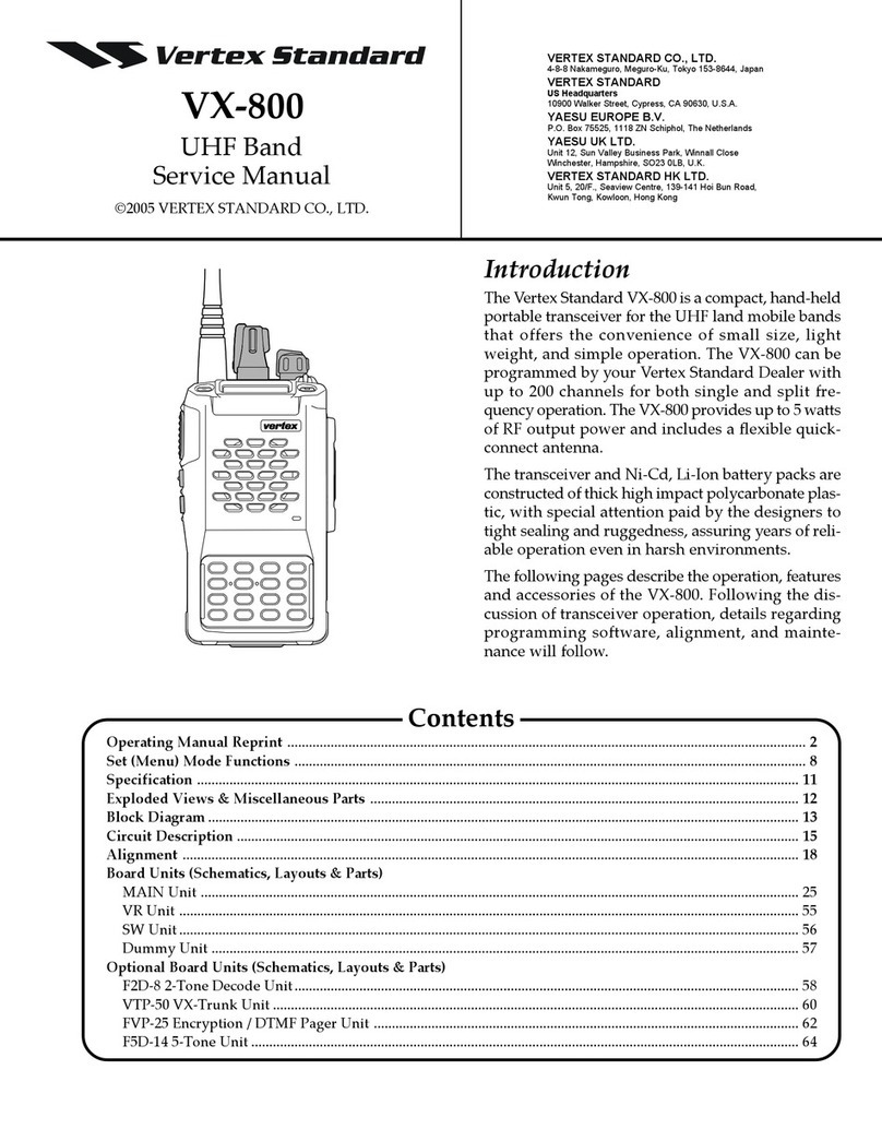
Vertex Standard VX-800 Service manual
