Alitronika DVS AT88IP User manual

Digital Video Interfacing Products
AT88IP
TS-over-IP
Receiver/Converter/Recorder
DVB-T2/T/C to DVB-ASI & IP Converter
Pro-MPEG Code Of Practice #3(COP3) FEC
Standard Features Application
DVB-T2/T/C to IP & DVB-ASI Receiver, Recorder Converter.
-Receives DVB-T2/T/C TS & converts into ASI & IP in real time.
-Records TS using Free application DVSStationIP.
-Web based Software as well as DVSStationIP.
-DVSStationIP runs on Windows XP, Vista, Windows 7.
-Remote Web-based configuration management.
-Remote firmware upgrade.
-Saved configuration settings.
-No re-configuration needed after system reboot.
-An alternative to dedicated satellite links.
-Connects digital video equipment to computer networks.
-Encapsulation of the TS data for Ethernet uses IP and the UDP),
with RTP encapsulation and Pro-MPEG COP3 FEC as an option.
-Dedicated hardware performs the encapsulation,
which maximizes the throughput and minimizes latency.
Targeted for Digital Video Professionals,
Sophisticated End Users and OEMs
the AT88IP is an ideal solution for a
number of applications such as:
-Development Tools.
-DVB to IP Gateway.
-Video on Demand Server.
-Transport Stream Test Generator.
-Studio to Transmitter Links.
-ENG (Electronic News Gathering) Stream
content to and from remote locations.
-ASI input to Cable System.
-Providing an ASI input for decoders,
Multiplexers, Modulators.
Specifications
IP
-IP Maximum rate of up to 214 Mbps per ASI channel.
-Network jitter correction.
-Supports constant bit rate ASI output.
-IP address assignment from DHCP server & static IP.
-IP address also configurable through the web interface.
-Configuration for Time To Live (TTL) for Multicast.
DVB-T2/T/C Input
-RF Tuner Connector: 75 Ohms IEC female Type.
-Loop Through Connector: 75 Ohms IEC male Type.
Input Frequency Range:
-High Band: 434.0 MHz to 858.0 MHz.
-Mid Band: 149.5 MHz to 426.0 MHz.
-Low Band: 50.5 MHz to 142.5 MHz.
-Channel Bandwidth: 6, 7 & 8 MHz.
-RF Sensitivity: -80dBm
-COFDM Spectrum (DVB-T2/T):
2k and 8k carriers non-hierarchical and hierarchical.
-Modulation Modes: DVB-T/T2: QPSK, 16QAM, 64QAM
-Modulation Modes: DVB-C: 64QAM, 128QAM, 256QAM
-Guard Interval Modes: 1/4, 1/8, 1/16, 1/32.
DVB-IP
-Ethernet encapsulation: IEEE 802.2 SNAP, Eth.
-Encapsulation: UDP or RTP
-IP support: IPv4
-IP-address assignment: DHCP link local or static
-Multicast support: IGMPv2
-Date Rate: 100/1000
-GigE port Physical layer: IEEE 802.3a
-GigE port Connector: RJ-45 with LEDs
-FEC: Pro-MPEG Code Of Practice #3(COP3)
-TSoverIP to ASI latency: Less than 1ms
-Jitter tolerance range: 500ms
DVB-ASI
-Port Physical layer: EN50083-9
-Connector: 75 Ohms Mini BNC
-Input Return Loss: >15 dB.
-Input Signal level: 800 mV +/-10%
-Output Signal level: 1.0Vp-p nominal.
-Input/Output Bit Rate: 0 to 214 Mbit/s.
DVB-T2/T/C
-Standards: DVB-T2/T/C.
© 2017 Alitronika DVS AT88IP www.alitronika.com

The block diagram of the AT88IP device.
The external interfaces for the AT88IP are shown. There are two F-Type RF connectors, a Mini
BNC connector for the DVB-ASI output, a RJ45 connector with two LEDs, a Power Supply Inlet and
a Power Switch.
Only the power adaptor supplied by Alitronika with this device should be used. These power
supplies are carefully selected for output voltage, current & power ratings as well as noise level.
Using any other power supplies will affect the performance of the device for sure and may damage
the device’s internal components permanently which is not covered by the warranty.
The three LEDs in front of the unit function as follows:
Top LED -Power
ON = Power is on
OFF = Power is off, No power
Middle LED -Status1
OFF = After power up this LED should be Blinking, if not something is wrong!
ON = When the device has connected correctly with the IP Network.
Bottom LED –Status2
OFF = This LED is off after power up
ON = When the device has SYNC to any incoming and/or out going TS.
1 BLOCK DIAGRAM
2 EXTERNAL INTERFACES
© 2017 Alitronika DVS AT88IP www.alitronika.com

The AT88IP device operates in a stand-alone mode. RF input & IP parameters are set using the Remote Web-based
configuration management application. As such there are no need for any other application software. However
DVSStationIP, the IP version of Alitronika’s DVSStation3/4/IP application software is provided FREE of charge with
these devices. Please follow these steps for problem free operation of the device.
Step 1: Application Software
Download the application software, DVSStationIP, from our website.
Link : www.alitronika.com/downloads.htm
Unzip it & install it on a PC/Laptop.
Step 2: Starting for the first Time
Connect the AT88IP & the PC/laptop to your network DHCP server.
Connect the power adaptor & Power up the AT88IP using the switch on the rear of the unit.
You should see the Power LED is ON and the 2nd LED ( Status1 ) BLINKING.
Start DVSStationIP.
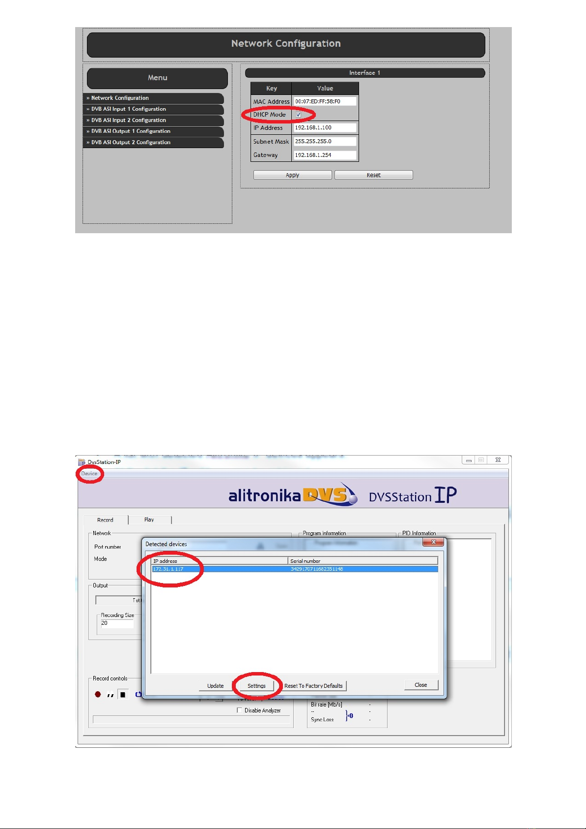
From the top bar, Device, use “Discover“ in order to find the IP address of AT88IP.
Once the device (s) is detected, a pop up screen opens. There are 3 options to be selected:
1-Update –This function is for updating the devices firmware.
2-Settings –Starts the Remote Web-based configuration management application.
3-Reset –This function resets the device to its original factory settings. This function can be
used whenever the user has lost theIP address or password.
3 INSTALLATION
© 2017 Alitronika DVS AT60IP www.alitronika.com

Step 3: Updating the Firmware if needed
If your system is working OK, you do not to update the Firmware, even if newer versions are available.
When you update the firmware you must wait for the process to complete without any interruptions. If the updating
is interrupted, by disconnecting it from the network or powering it down, the device will no longer have a valid firmware
& no longer operates.
© 2017 Alitronika DVS AT88IP
www.alitronika.com

Step 4: Remote Web-based configuration management application
Longin is required in order to enter the web-based application.
© 2017 Alitronika DVS AT88IP www.alitronika.com

Once the configuration management starts the screen below can be seen.
The “Network Configuration” screen is opened by default.
The MAC Address, IP Address, Subnet Mask & the Gateway address can bee seen.
The user can change any of these & then clicking on “APPLY”.
It is assumed the user is familiar with IP terms.
The DHCP Mode could be selected/De-selected.
© 2017 Alitronika DVS AT88IP www.alitronika.com

Step 5: Setting the DVB-T2/T/C De-modulator parameters.
As it can bee seen from the screen shot below, in order for correct operation of the DVB-T2/T/C Receiver/Demodulator
section, a few parameters must be set by the user.
Notice the DVB-T2/T/C input port must first be ENABLED.
Selecting De-modulation mode: The AT88IP has 3 modes, DVB-T2, DVB-T and DVB-C. The user can select any of
these from the top level of Web-based configuration management application.
Once a mode ( T2, T or C ) is selected the following settings can be selected by the user.
1-Demodulator Settings-Here only two parameters need setting, the FREQUENCY & the BANDWIDTH for
DVB-T and only the FREQUENCY settings for DVB-C.
2-IP Encapsulation Settings
3.1-Mode –RTP or UDP
3.2-Packet Number –Transport Packets are converted & send via IP in bursts.
The number of packets per burst could be selected from 1 to 7.
Refer to DVB over IP documents if you wish to know more about this. Also see Appendix1.
3-Pro-MPEG FEC Settings
Again it is assumed the user knows about DVB-over-IP.
It is clear when sending Transport Streams over IP ( or anything over IP ), data could get lost or corrupted.
Forward Error Schemes such as Pro-MPEG Code Of Practice #3(COP3) FEC are used to recover the data.
The user has control over the FEC.
FEC adds additional overhead to the data transfer over IP network.
4.1-Enabling the FEC –User is able to Enable or Disable the FEC function.
It is matter of trade-off between the speed & quality.
We assume the user knows what is the best here.
4.2-Number of Columns & Rows ( L & C ) –Refer to DVB over IP for this. Also see Appendix1.
4.3-Interleaver Mode -Refer to DVB over IP for this. Also see Appendix1.
4-IP Settings –The DVB-T2/T/C Transport Streams are Received, De-modulated & after being processed
according to all of the user selected settings above, it send to IP address. The user has also control over
where the streams are going.
5.1-Target IP Address –Select an IP address for Unicast or select 255.255.255.255 for Multicast.
5.2-Target Port –User can also select the port number.
Notes :
-Click on Apply to save the selected settings on the non-volatile memory of the AT88IP device.
The device will operate with these parameters until the user changes them.
No re-configuration needed after system reboot.
-All modulation parameters related to DVB-T2/T/C RF input and the incoming transport streams are detected
automatically by the integrated TS Analyser. No user inputs are required.
© 2017 Alitronika DVS AT88IP www.alitronika.com

© 2017 Alitronika DVS AT88IP www.alitronika.com
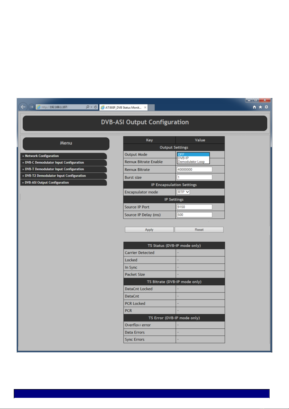
Step 6: Setting the DVB-ASI output parameters.
The DVB-ASI output of AT88IP is completely independent of the DVB-T2/T/C input.
This port is a device on its own.
It could be configured as follows :
1-It could be turned off altogether.
2-It can be used as DVB-T2/T/C to DVB-ASI converter to convert the incoming transport stream to be used for
example as input of a decoder or a modulator. It could be used to monitor the incoming transport stream or any
other function.
3-It could also be used as an independent DVB-ASI output of TS over IP converter.
A completely different transport stream could be ported out of this output.
Another use for it could for example be to port the input DVB-T2/T/C transport stream after some processing
such as Multiplexing, Re-Multiplexing, PID filtering, Trans-coding, Logo inserting.
In such a case the TS enters the system via the IP network, processing is carried out on it & is send out as a
new transport stream via IP network to be used elsewhere is the system.
© 2017 Alitronika DVS AT88IP www.alitronika.com

AT88IP operates as a stand-alone device. DVSStationIP could be used to add even more functions & features to it.
1-Up-dating the firmware
2-Finding the device’s IP address with “Discover” function when not used with a fixed IP address.
3-Recording & monitoring the incoming transport stream.
4-Play back any transport streams
4 APPLICATION SOFTWARE
© 2017 Alitronika DVS AT88IP www.alitronika.com

In order to view the programs any software decoder could be used.
Most of them could be downloaded from the Internet FREE of charge.
One such software is the VideoLan. Use this like to download http://www.videolan.org/.
Once install on your system.
-From “Media” => Open Network Stream
-Type in “rtp://@:9150” for example ( if you are using RTP mode & the Port is 9150 )
-From “Playback”=> Click on “Programs” and select the desired program for the list to view.
5 SOFTWARE DECODERS
© 2017 Alitronika DVS AT88IP www.alitronika.com

© 2017 Alitronika DVS AT88IP www.alitronika.com

Appedix1
DVB-IPI (ETSI TS 102 034) specifies protocols at the IP networking layer (IP Infrastructure) that must
be supported on key system interfaces to deliver DVB services over IP networks.
Below are presented the main points on MPEG2 TS over IP Encapsulation set by DVB-IPI.
All MPEG-2 transport streams shall be encapsulated in RTP (Real-time Transport Protocol) according to
RFC 1889 in conjunction with RFC 2250. Transport service is provided jointly by UDP (checksum and
multiplexing) and RTP (sequencing and time stamping / jitter removing).
RTP always uses an even UDP port number.
-V -Version, 2 bits. This field identifies the version of RTP.
-P -Padding, 1 bit. If the padding bit is set, the packet contains one or more additional padding bytes.
-X -Extension, 1 bit. If set, the fixed header is followed by exactly one header extension.
-CC -CSRC count. The CSRC count contains the number of CSRC identifiers that follow the fixed header.
-M -Marker, 1 bit. The interpretation of the marker is defined by a profile.
-PT -Payload type, 7 bits. Identifies the format of the RTP payload and determines its interpretation by the application.
-Sequence number Sequence number, 16 bits. The sequence number increments by one for each RTP data packet
sent and may be used by the receiver to detect packet loss and to restore packet sequence.
-Timestamp Timestamp, 32 bits. The timestamps reflects the sampling instant of the first byte in the RTP data packet.
-SSRC Synchronization source, 32 bits. Identifies the synchronization source.
-CSRC Contributing source, 0 to 15 items, 32 bits each. An array of 0 to 15
-CSRC elements identifying the contributing sources for the payload contained in this packet.
For most streams, the RTP/UDP/IP overhead of 40 bytes per RTP packet is relatively low (for example 3% with a 1 316
byte payload).
IP packets can carry from 1 to 7 TS packets, knowing that:
–overall size of RTP payload must not exceed the MTU (Maximum Transfer Unit) in order to prevent RTP packets
fragmentation around the network,
–short packets cause a high overhead.
There is no requirement for every RTP packet in a stream to contain the same number of transport
stream packets. The receiver should use the length field in the UDP header to determine the number of
transport stream packets contained in each RTP packet. The time stamp field in RTP header is based on the PCR
values from MPEG-2 with a resolution of 90 KHz.
Streams must include PAT (Program Association Table) & PMT (Program Map Table) –other tables are optional. SI
(Service Information) is intended to be delivered via separate IP streams, in e.g. XML format. RTCP (Real-time
Transport Control Protocol) can be included to periodically inform the sending side about network quality (e.g. lost
packets, delay, jitter, etc.).
The fact is that, at the output of the IP network, delivered Transport Stream must be fully ISO/IEC 13818-1 compliant
(40ms maximum jitter, 1 artifact every hour...).
Forward Error Correction
The Pro-MPEG Forum (association of broadcasters, program-makers, and vendors) approved an open
standard to improve QoS in professional video over IP networks, while keeping interoperability between equipment
manufacturers.
Standard is provided as a set of guidelines and recommendations (Codes of Practice).
Code of Practice #3 describes a Forward Error Correction (FEC) method for protection against errors in delivering
professional MPEG-2 TS data over IP networks. This method implemented in IP adapters, packet errors, out of order
packets, network jitter and delay can be compensated. Such process is done in real-time along with TS over IP
encapsulation.
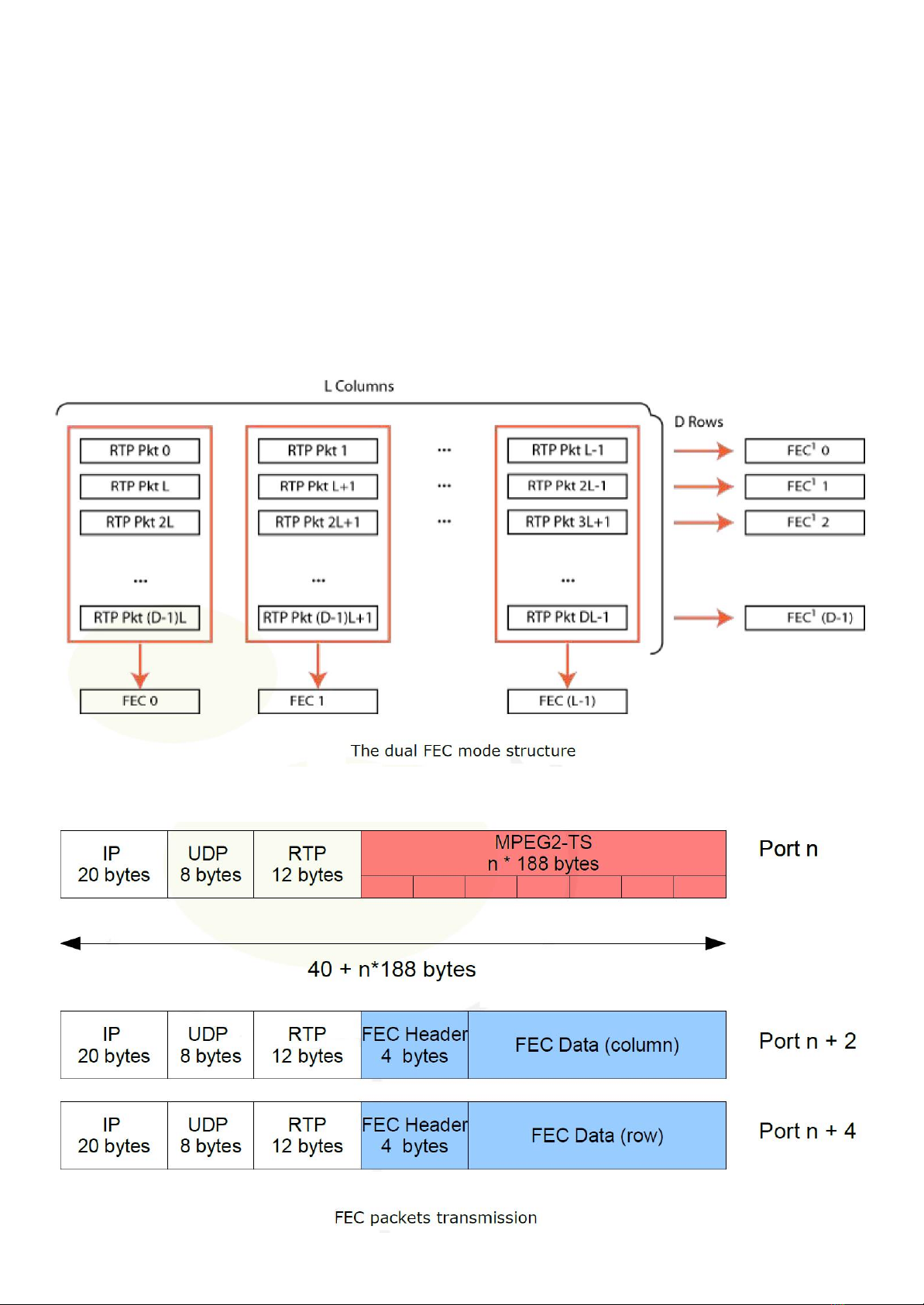
FEC protection data is calculated and embedded in regular RTP packets with a specific payload type, and relies on
simple XOR arithmetic’s (if F=A?B?C, then if only A,B,F are present, C can be recovered with C=A?B?F). A FEC matrix
is generated (cf figure 3) and transmitted on two separate UDP ports, FEC columns on UDP port + 2 and FEC rows on
UDP port + 4.
Appendix2 -Multicast
All Alitronika IP devices have the capability to transmit or receive a transport stream by unicast, multicast
or broadcast. This appendix describes the multicast settings.
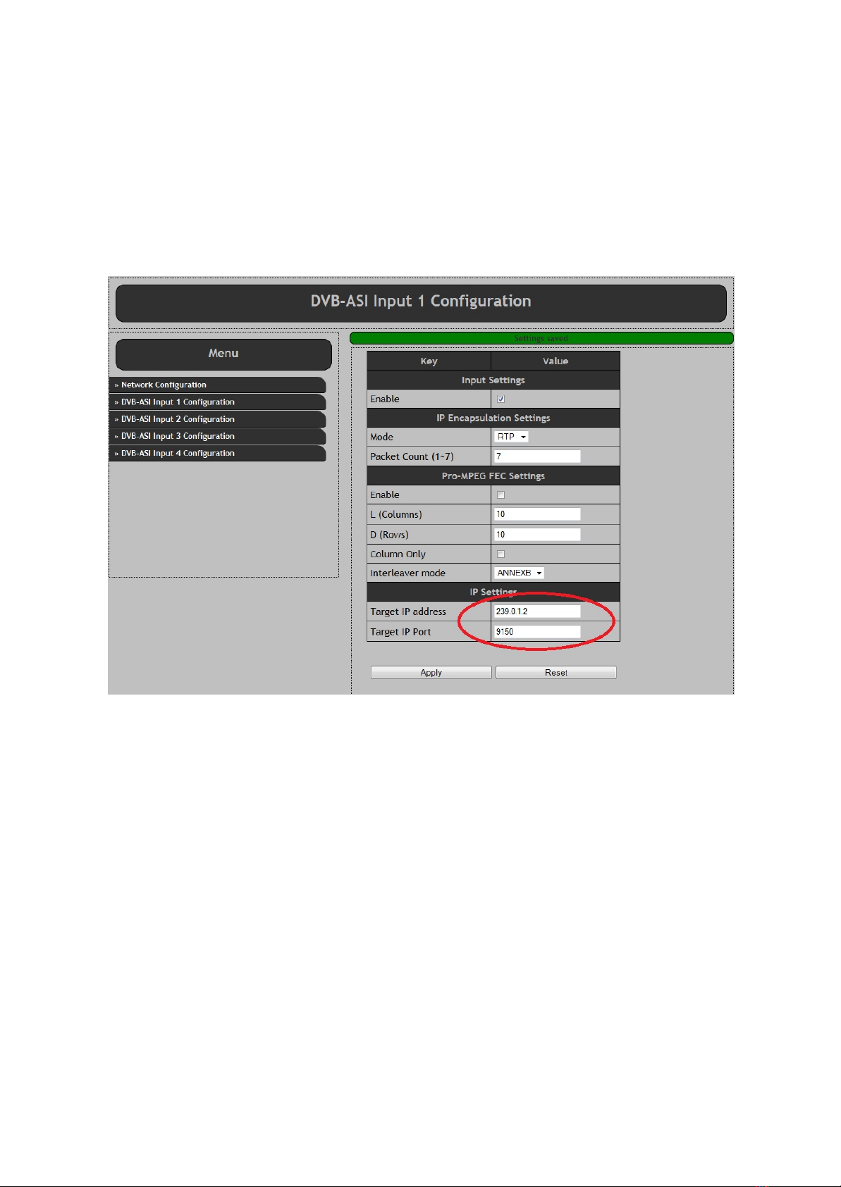
2.1 Multicast Transmit
In order to enable multicast transmit, the target IP address must be set to a value in the multicast range.
The multicast range is from 224.0.0.0 to 239.255.255.255.
Also the target IP port number must be set.
The screen shot below from AT240IP is shown as an example. TheAT88IP has the same settings.
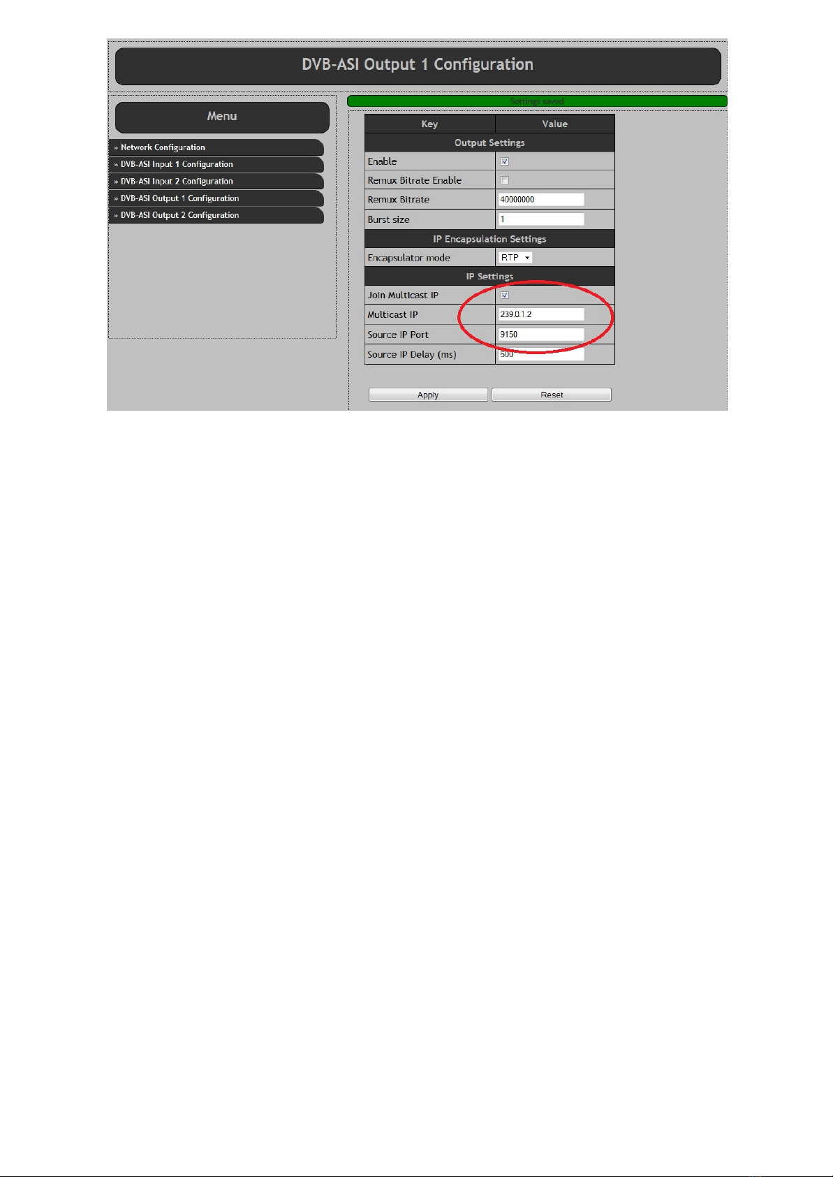
2.2 Multicast Receive
To receive the multicast stream at another device the device must be set up as follows:
-First the multicast IP address must be set.
This needs to be the same as the multicast transmitter IP address.
-Second the port number must be set.
This needs to be the same as the as the multicast transmitter port number.
-Finally the “Join multicast IP” check box must be enabled.
When enabled, the device sends a multicast join group message to the Ethernet network switch. The switch
then enables sending the transport stream to the device.
When the “Join multicast IP” check box is disabled, the device sends a leave multicast group message to
the switch. The switch then disables sending the transport stream to that device.
When the “Join multicast IP” check box is disabled, the “Multicast IP” address is ignored.
2.3 RIGMP Querier
The join and leave multicast group messages belongs to the IGMP protocol. Most switches have a timeout
at the multicast group table. The timeout can be named “Host timeout” or “Aging timeout”.
At the timeout the multicast group is cleared and multicasting stops.
To avoid this the following can be done:
•Increase “Host timeout”/“Aging timeout” value.
•Configure the multicasting manually at the switch.
•Install an IGMP Querier in the network.
•Use the internal IGMP Querier of the switch (if the switch supports this).
2.3 DHCP or Static IP address
All Alitronika IP devices have the option to obtain the IP address by a DHCP server or to set a static IP address.
2.3.1 DHCP
To obtain the IP address by a DHCP server the device must be set as followings:
•Switch on the device.
•Open the devices settings web interface.
•Select the “Network Configuration” page.
•Select the “DHCP Mode” checkbox.
•Press Apply.
•Restart the device.
In DHCP mode the IP address, Subnet Mask and Gateway settings are ignored.
DHCP or static IP address
2.3.2 Discover device
If the device uses DHCP mode, the IP address is unknown. To discover the device, DVSStationIP must be
used.
Use the following procedure to discover the device:
•Switch on the device.
•Open DVSStationIP.
•Click on the “Device” menu item and select the “Discover IP Devices”.
•A list with detected Alitronika IP devices appears.
•The IP address can be retrieved.
•Select the device and press the “Settings” button to open the web interface.

2.3.3 Static IP address
With a static IP address the device always starts with the same IP address.
To use the static IP address the device must be set as follows:
•Switch on the device.
•Open the devices settings web interface.
•Select the “Network Configuration” page.
•Deselect the “DHCP Mode” checkbox.
•Enter a valid address at the “IP Address” field. Please note that the IP address must be in the
same IP range of the local network, else the device could be unreachable.
•Enter a valid address at the “Submask” field.
•Enter a valid address at the “Gateway” field. (Normally the IP address of the modem).
•Press Apply.
•Restart the device.
After restart the device uses the static IP address.

2.4 Recovering from a faulty Static IP address
If a faulty static IP address is set, the device could be unreachable. To recover from this situation,
DVSStationIP must be used.
Use the following procedure to recover the device:
•Switch on the device.
•Open DVSStationIP.
•Once DVSStationIP is active click on the “Device” menu item and select the “Discover IP Devices”.
•A list with detected Alitronika IP devices appears.
•Select the device with the faulty IP address and select the “Restore to Factory Defaults” button.
•The device now restores the default settings with DHCP mode enabled.
•The device restarts automatically.
•Wait until the device re-appears in the device list with a new and correct IP address.

2.5 References (ordered from 'user understandable' to protocol description):
http://www.juniper.net/documentation/en_US/junos12.1/topics/concept/igmp-snooping-multicast-
forwarding.html
https://en.wikipedia.org/wiki/Internet_Group_Management_Protocol
http://wiki.mikrotik.com/wiki/Manual:Multicast_detailed_example
https://tools.ietf.org/html/rfc2236
https://tools.ietf.org/html/rfc3376
2.5 Video Tutorial:
https://www.youtube.com/watch?v=GGqcwdDW1a8 (Cisco Multicast IGMPv2)
2.6 Dumb tool, which can act as IGMP Querier application:
https://code.google.com/p/igmpquery/
Table of contents


