Albatross AlbaCombi User manual


The AlbaCombi has been certified to comply with the European directive for
Electromagnetic Compatibility (EN60945) and is appropriately CE marked. Operation
of the unit should be in conjunction with appropriate CE approved shielded
connectors and cabling used in accordance with the CE directive EN60945. Any EMC
related issues should be reported to Emmi Network S.L. immediately to allow the
company to rectify or resolve EMC related problems in accordance with its obligations
under EN60945.
Product Disposal
Please dispose of this product in accordance with the WEEE Directive. The product should be
taken to a registered establishment for the disposal of electronic

INDEX
1.PRODUCT OVERVIEW.............................................................................................................1
1.1 Specifications ............................................................................................................2
1.2 PGNs Supported ........................................................................................................3
1.3 Din Rail Mounting......................................................................................................4
1.4 NMEA2000 Cable Connection ....................................................................................5
1.5 NMEA2000 Networks ................................................................................................8
1.6 Power Supply input of AlbaCombi..............................................................................9
1.7 NME2000 Minimum Network Requirements .............................................................9
2. Installation & Configuration ..................................................................................................9
2.1 First Start and IP Configuration and AlbaCombi Web-Interface......................................10
2.1.1 For Windows ..........................................................................................................10
2.1.2 For Mac ..................................................................................................................14
3. AlbaCombi Web Interface ...................................................................................................16
3.1 “GENERAL” Option ........................................................................................................16
3.2 “BACKUP” Option..........................................................................................................17
3.3 “CHANNELS” Option......................................................................................................17
3.3.1 RPM Inputs.............................................................................................................18
3.3.2 PTC1000 Input ........................................................................................................20
3.3.3 Voltage or Resistive Inputs......................................................................................22
Calibration Curve Example ..................................................................................................26
3.3.4 Shunt Input.............................................................................................................30
3.3.5 Voltage Inputs ........................................................................................................32
3.4 “OUTPUT” Option..........................................................................................................33
3.5 “N2K” Option ................................................................................................................34
3.5.1 PGN127488 Engine Rapide Update .........................................................................35
3.5.2 PGN127489 Engine Parameter Dynamic .................................................................36
3.5.3 PGN127508 Battery Status......................................................................................37
3.5.4 PGN127505 Fluid Level ...........................................................................................38
3.5.5 PGN130312 Temperature .......................................................................................39
3.5.6 PGN130314 Pressure ..............................................................................................40
Configure AlbaCombi N2K into your Plotter.........................................................................40
3.6 “DISPLAYS” Option ........................................................................................................47
3.7 “FULLVIEW” Option.......................................................................................................49
4. Tacho Inputs .......................................................................................................................51
4.1 Ignition Coil...................................................................................................................51

4.2 Alternator .....................................................................................................................51
4.3 Hall Effect and Electronic Pulse Senders ........................................................................51
5. Sensor 4 to 20mA sensors ...................................................................................................52
6. Hardware Test Mode and Setup mode ................................................................................53
7. Firmware Update ................................................................................................................56
8. Connecting two or more AlbaCombi units ...........................................................................57
9. How to visualize AlbaCombi to your Tablet or Smartphone .................................................57
10. Basic Configurations..........................................................................................................59
11. Troubleshooting................................................................................................................60
12. Company Information .......................................................................................................61

1
1.PRODUCT OVERVIEW
The new AlbaCombi is a second-generation device, built following our successful Alba line of
converters, that translate analogue signals from all over the boat to an NMEA2000 BUS.
The unit has been designed to connect in parallel to an existing gauge, so existing instruments
can still be used.
The AlbaCombi can be used to get engine data, tank levels, alarm status, generic pressure, and
temperature indications from any 4-20mA sensor.
You get twelve 0V to 32V inputs that can be used for anything from reading voltages of batteries
to interfacing with any analogue gauges. Six channels can be configured to measure resistance
from any industry standard engine sensor.
Also, there are two RPM inputs, one PTC temperature input, one shunt and two relay outputs.
All twelve resistance and voltage channels have comprehensive calibration that allow you to
create an 8-point calibration table or select a predefined industry standard calibration table for
most common sensors and gauges.
The AlbaCombi has an Ethernet port that will allow web-based calibration. Just connect your
laptop to the Alba-Combi via Ethernet and you will get to the calibration and testing page. No
calibration tools or special interfaces required. This device is future proof and can be upgraded
in the field via its ethernet port.

2
1.1 Specifications
IMPORTANT: In older versions of AlbaCombi maximum Voltage allowed to power supply the
AlbaCombi was 9-18V DC. If you have any doubts to know which version, do you have, please
contact us

3
1.2 PGNs Supported
The Alba-Combi will convert all those channels to temperature, pressure, voltage, tank levels,
current, engine status, etc. You will be able to use that information to populate all the available
15 NMEA2000 PGNs.
PGN 127488 –Engine Parameters, Rapid Update (2)
PGN 127489 –Engine Parameters, Dynamic (2)
PGN 127493 –Transmission Parameters, Dynamic (2)
PGN 127508 –Battery Status (3)
PGN 127505 –Fluid Level (4)
PGN 130316 –Temperature, Extended Range (4)
PGN 130314 –Pressure (1)
PGN 130576 –Trim Tab Status (1)
Screenshot from web-interface (N2K Option)

4
1.3 Din Rail Mounting
Requirements:
A top hat rail, type EN 50 022 or a G section rail, type EN 50 035.
Mounting using a different rail type or an alternative mounting kit may breach the terms and
conditions of the guarantee.
5
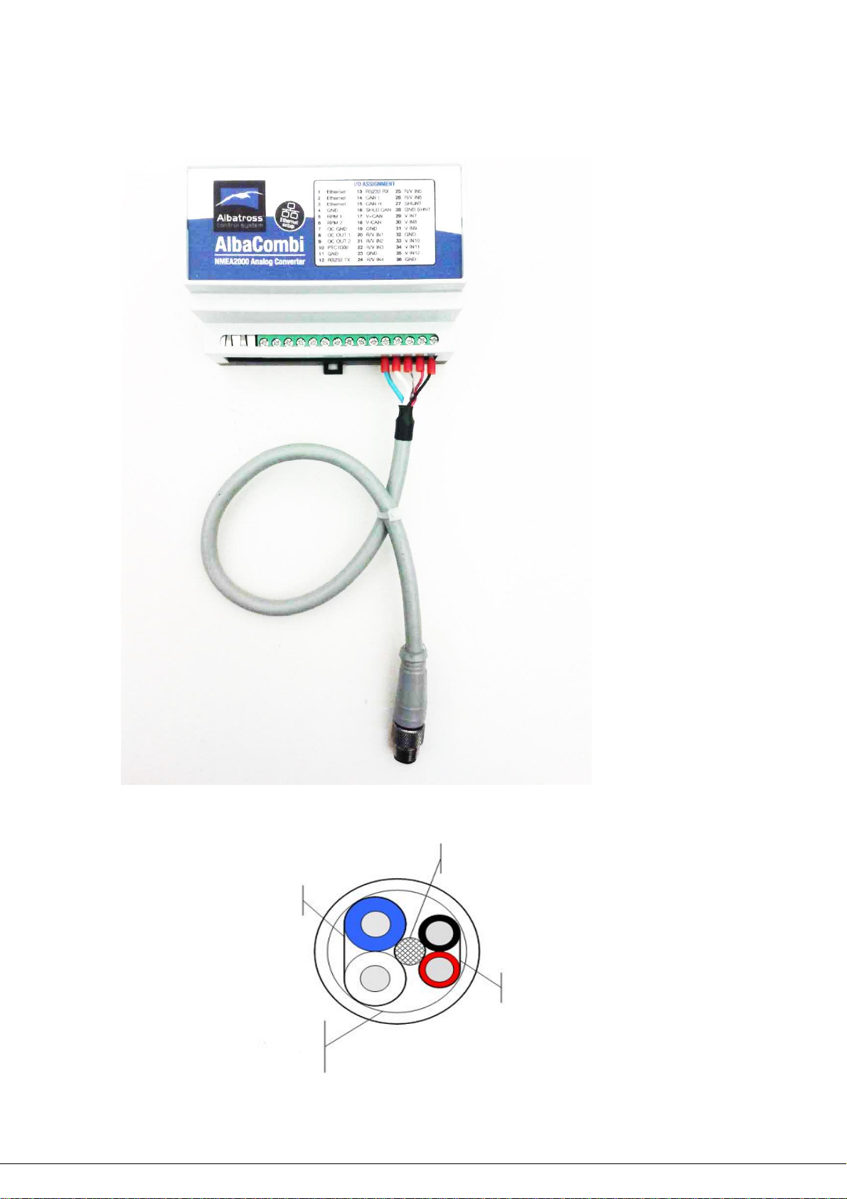
1.4 NMEA2000 Cable Connection
Protective braid
Data:
Blue: NET-H (CAN-H)
White: NET-L (CAN-L)
Feed:
Red: NET-S. Positive Feed +V
Black: NET-C. Common Feed -V
External protective braiding
Normal connection with a NMEA2000 Spur Cable

6
For Raymarine SeatalkNG Network you can use the following:
Connection with a stripped cable SeatalkNG Cable (Raymarine N2K cable).
You can use the SeatalkNG Spur Cable (ref: A06043), sold separately . With you can connect
directly
Other manuals for AlbaCombi
1
Table of contents
Other Albatross Media Converter manuals


