FS MMC-1SC1T-SM User manual

Managed Ethernet
Media Converter
Configuration Guide
Models: MMC-1SC1T-SM/MMC-1F1T
CONFIGURATION GUIDE

MANAGED ETHERNET MEDIA CONVERTER CONFIGURATION GUIDE
www.fs.com
1
Contents
1. Introduction......................................................................................................................................................................................................2
1.1 About the Managed Media Converter...................................................................................................................................................2
1.2 Product Features.................................................................................................................................................................................... 2
2. Media Converter Management...................................................................................................................................................................... 3
2.1 Overview.................................................................................................................................................................................................3
2.2 Management Methods...........................................................................................................................................................................3
2.2.1 Web Management.....................................................................................................................................................................3
2.2.2 SNMP Management.................................................................................................................................................................. 3
2.2.3 Login the Managed Media Converter.......................................................................................................................................4
3. WEB Management............................................................................................................................................................................................5
3.1 Main Menu..............................................................................................................................................................................................5
3.2 System.................................................................................................................................................................................................... 6
3.21 System Information....................................................................................................................................................................6
3.3 Port Management................................................................................................................................................................................ 17
3.3.1 Port Configuration...................................................................................................................................................................17
3.3.2 Port Status............................................................................................................................................................................... 20
3.3.3 Port Statistics........................................................................................................................................................................... 21
3.4 Converter Configuration...................................................................................................................................................................... 22
3.5 VLAN..................................................................................................................................................................................................... 23
3.5.1 VLAN Group.............................................................................................................................................................................25
3.5.2 VLAN per Port Setting............................................................................................................................................................. 27
3.5.3 Q-in-Q VLAN Setting................................................................................................................................................................28
3.6 Quality of Service..................................................................................................................................................................................29
3.7 OAM Setup........................................................................................................................................................................................... 31
3.7.1 Local TS-1000 OAM Setup.......................................................................................................................................................31
3.7.2 Remote TS-1000 OAM Setup...................................................................................................................................................32
3.7.3 TS-1000 Loop Back Test.......................................................................................................................................................... 33
3.7.4 802.3ah Setup..........................................................................................................................................................................35
3.7.5 802.3ah Loop Back Test...........................................................................................................................................................36
3.8 Security................................................................................................................................................................................................. 38
3.9 Logout.................................................................................................................................................................................................. 39

MANAGED ETHERNET MEDIA CONVERTER CONFIGURATION GUIDE
www.fs.com
2
1.
Introduction
1.1
About the Managed Media Converter
The Managed Media Converter provides conversion between 10/100/1000Base-T and 1000Base-X network. There are SC and SFP
connectors with single mode or multimode media types for your needs. Ethernet signal allows two types of segments connecting easily,
efficiently and inexpensively.
The Managed Media Converter is equipped with a remote Web/SNMP interface. With its built-in Web-based management, the Managed
Media Converter offers an easy-to-use, platform-independent management and configuration facility and can be programmed for
advanced management functions. Such as IP address Configuration/DHCP Client function, password setting/firmware upgrade, system
reboot/factory default, port configuration that includes TP/Fiber port speed duplex mode setting, flow control setting and Ingress/Egress
bandwidth control setting, converter configuration that includes maximum packet length setting, Broadcast/Multicast/Unicast storm
control setting, 16 IEEE 802.1Q VLAN groups support and powerful Q-in-Q VLAN function, Quality of Service (QoS), TS-1000/ IEEE 802.3ah
OAM function and TCP & UDP filter function. It supports standard Simple Network Management Protocol (SNMP) and can be managed via
any standard-based management software as well.
With high performance of data transmission and easy installation, the Managed Media Converter can build an ISP network solution of
FTTH (Fiber to the Home) or FTTC (Fiber to the Curb) for ISPs and FTTB (Fiber to the Building) for small office network environment from
enterprises. The Web Management helps network administrators to monitor and set up the converter, speed and duplex through web
browsers.
1.2
Product Features
• Comply with IEEE 802.3 / IEEE 802.3u/ IEEE 802.3ab/ IEEE 802.3z
• TP port supports 10/100/1000Base-T auto-negotiation and auto-MDI/MDI-X
• 1000Base-T: 2-pair Cat. 5/5e/6 UTP cable, up to 100 meters
• Built-in IP-Based Web interface for remote management
• Layer 2 Management Feature
• Store-and-Forward mechanism
• Built-in Web operation interface for remote management and setup
• Manual IP address setting/DHCP client for IP address assignment
• SNMP v1/v2c monitor/private Enterprise MIB
• Event trap and SNMP trap support
• Speed duplex mode configuration/Flow Control setting/bandwidth Control on TP/Fiber port
• Supports Port Status/Ethernet Statistics on both TP and Fiber interface
• Supports Maximum frame size to 16K bytes
• Loop detection/Broadcast/Multicast/Unicast storm control
• Management VLAN/16 IEEE 802.1Q VLAN groups/Q-in-Q VLAN
• 802.1p Tag Priority/IP address priority/IP DSCP option in Quality of Service Mode and Strict Priority/Weighted Round Robin
(WRR) QoS policies
• TS-1000 OAM/IEEE 802.3ah OAM/Loop Back Test
• 16 TCP/UDP Filter groups
• Password setting, IP setting and devices description setting through Planet Smart discovery utility
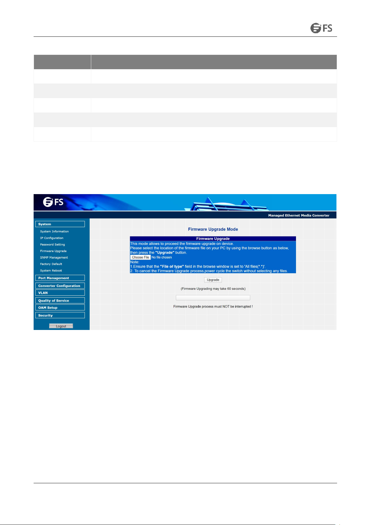
• Firmware upgrade via remote Web interface
• External DC 5V 2A power supply
• Compact in size, easy installation
• LED indicators for easy network diagnosing
• Reset Button at the front panel for resetting the factory default

MANAGED ETHERNET MEDIA CONVERTER CONFIGURATION GUIDE
www.fs.com
3
2.
Media Converter Management
This chapter describes how to manage the Managed Media Converter. Topics include:
•Overview
•Management methods
•Assigning an IP address to the Managed Media Converter
•Logging on to the Managed Media Converter
2.1
Overview
This chapter gives an overview of Managed Media Converter management. The Managed Media Converter provides a simple WEB
browser interface. Using this interface, you can perform various Managed Media Converter configuration and management activities,
including:
•System
•Port Management
•Converter Configuration
•VLAN
•Quality of Service
•OAM Setup
•Security
•Logout
Please refer to the following Chapter 3 for more details.
2.2
ManagementMethods
The way to manage the Managed Media Converter:
• Web Management via a network or dial-up connection
• Using SNMP Network Management Station
2.2.1 Web Management
The Managed Media Converter provides a built-in browser interface. You can manage the Managed Media Converter remotely by having
a remote host with Web browser, such as Microsoft Internet Explorer, Netscape Navigator or Mozilla Firefox.
The following shows how to startup the Web Management of the Managed Media Converter, please note the Managed Media Converter
is configured through an Ethernet connection, make sure the manager PC must be set on the same IP subnet address, for example, the
default IP address of the Managed Media Converter is 192.168.0.100 (the factory-default IP address), then the manager PC should be set
at 192.168.0.x (where x is a number between 1 and 254, except 100), and the default subnet mask is 255.255.255.0.
Use Internet Explorer 6.0 or above Web browser, enter default IP address http://192.168.0.100
After entering the username and password (default username and password is “admin”) in login screen, then the Web main screen
appears.
2.2.2 SNMP Management
You can manage the Managed Media Converter across a LAN using an SNMP Network Management Station with a graphical user interface.
This management method lets you monitor statistical counters and set Managed Media Converter parameters from the remote Network
Management Station.
Using this management method:
• The network must run the IP protocol.
• The Managed Media Converter must have an IP address.

MANAGED ETHERNET MEDIA CONVERTER CONFIGURATION GUIDE
www.fs.com
4
2.2.3 Login the Managed Media Converter
Before you start configuring the Managed Media Converter, please note the Managed Media Converter is configured through an Ethernet
connection, make sure the manager PC must be set on same the IP subnet address. For example, the default IP address of the Managed
Media Converter is 192.168.0.100, then the manager PC should be set at 192.168.0.x (where x is a number between 2 and 254), and the
default subnet mask is 255.255.255.0. Use Internet Explorer 6.0 or above Web browser. Enter IP address http://192.168.0.100 (the factory-
default IP address) to access the Web interface.
When the following login screen appears, please enter the default username and password (default username and password is "admin").
Press Login to enter the main screen of Managed Media Converter. The login screen in Figure 2-1 appears.
Figure 2-1 Login Web Page Screen
NOTE:
(1) For security reasons, please change and memorize the new password after this first setup.
(2) Only accept command in lowercase letter under the web interface.

MANAGED ETHERNET MEDIA CONVERTER CONFIGURATION GUIDE
www.fs.com
5
3.
WEB Management
The Managed Media Converter provides Web interface for management function configuration and makes the Managed Media Converter
operate more effectively: they can be configured through the Web Browser. A network administrator can manage and monitor the
Managed Media Converter from the local LAN. This section indicates how to configure the Managed Media Converter to enable its
management function.
3.1
Main Menu
After a successful login, the main screen appears, the main screen displays the Managed Media Converter Welcome page. The screen in
Figure 3-1 appears.
Figure 3-1 Web Main Screen
As listed at the left of the main screen, the configurable management functions are shown as below:
•
System: Provide System configuration of Managed Media Converter. Explained in section 3.2.
•Port Management: Provide Port Management configuration of Managed Media Converter. Explained in section 3.3.
•
Converter Configuration: Provide Converter configuration of Managed Media Converter. Explained in section 3.4.
•
VLAN: Provide VLAN configuration of Managed Media Converter. Explained in section 3.5.
•
Quality of Service: Provide Quality of Service (QoS) function of the Managed Media Converter. Explained in section 3.6.
•
OAM Setup: Provide OAM Setup function of the Managed Media Converter. Explained in section 3.7.
•
Security: Provide Security function of the Managed Media Converter. Explained in section 3.8.
•
Logout: Provide Logout function of the Managed Media Converter. Explained in section 3.9.

MANAGED ETHERNET MEDIA CONVERTER CONFIGURATION GUIDE
www.fs.com
6
3.2
System
3.21 System Information
The System Information Web page provides information for the current device. System Information Web page helps network
administrator to identify the firmware versions, IP Subnet Address and etc. The screen in Figure 3-2 appears and Table 3-1 describes the
System Information object of Managed Media Converter.
Figure 3-2 System Information Web Page Screen
The System Information Web page screen includes the following fields:
Objects
Descriptions
MAC Address
Specify the MAC address of Managed Media Converter.
Hardware Version
The current hardware version of the Managed Media Converter.
Software Version
The current software version running on the Managed Media Converter.
IP Address
The current IP Address of Managed Media Converter, the default IP Address is 192.168.0.100.
Subnet Mask
The current Subnet Mask of Managed Media Converter, the default Subnet Mask is 255.255.255.0.
Gateway
The current gateway of Managed Media Converter, the factory default gateway is 192.168.0.254.
Description
The current description of Managed Media Converter, the factory default description is MMC-1SC1T-SM.
Table 3-1 Descriptions of the System Information Web Page Screen Objects

MANAGED ETHERNET MEDIA CONVERTER CONFIGURATION GUIDE
www.fs.com
7
3.2.2 IP Configuration
The IP Configuration includes the DHCP Client, IP Address, Subnet Mask, Gateway and Description. The screen in Figure 3-3 appears and
Table 3-2 describes the IP Configuration object of Managed Media Converter.
Figure 3-3 IP Configuration Web Page Screen
The IP Configuration Web page screen includes the following configurable data:
Objects
Descriptions
DHCP Client
Allow disabling or enabling the DHCP Client function of the Managed Media Converter, the factory default mode is
Disable.
IP Address
Allow assigning a new IP address for the Managed Media Converter, the factory default IP address is 192.168.0.100.
Subnet Mask
Allow assigning a new subnet mask for the Managed Media Converter, the factory default subnet mask is
255.255.255.0.
Gateway
Allow assigning a new gateway for the Managed Media Converter, the factory default gateway is 192.168.0.254.
Description
Allow inputting a new description for the Managed Media Converter, up to maximum 32 characters is allowed.
Apply Button
Press “Apply” button to save current configuration of Managed Media Converter.
Table 3-2 Descriptions of the IP Configuration Web Page Screen Objects
NOTE: After changing the default IP subnet address, if you forget the IP subnet address. Please press the “Reset” button in the front panel
of Managed Media Converter for 10 seconds, the current setting will be lost and the Managed Media Converter will restore to factory
default mode.

MANAGED ETHERNET MEDIA CONVERTER CONFIGURATION GUIDE
www.fs.com
8
3.2.3 Password Setting
This function provides administrator a secure Web login. The screen in Figure 3-4 & 3-5 appears and Table 3-3 describes the Password
Setting object of Managed Media Converter.
Figure 3-4 Password Setting Web Page Screen
Figure 3-5 Password Setting Successful Web Page Screen

MANAGED ETHERNET MEDIA CONVERTER CONFIGURATION GUIDE
www.fs.com
9
The Password Setting Web page includes the following configurable data:
Objects
Descriptions
Login Name
Display the username (admin).
Old Password
Entering the old password is required before entering the new password.
New Password
Specify the new password. The password is not displayed. As it entered an “*” corresponding to each
character displayed in the field. (The maximum length is 16 characters)
Confirm
This confirms the new password. The password entered into this field must be exactly the same as the
password entered in the New Password field.
Apply Button
Press “Apply” button to save current configuration of Managed Media Converter.
Table 3-3 Descriptions of the Password Setting Web Page Screen Objects
3.2.4 Firmware Upgrade
This function provides Firmware Upgrade of the Managed Media Converter and the screen in Figure 3-6 appears.
Figure 3-6 Firmware Upgrade Web Page Screen

MANAGED ETHERNET MEDIA CONVERTER CONFIGURATION GUIDE
www.fs.com
10
Press “Choose File” button to find the firmware location administrator PC. After finding the firmware location from administrator PC,
press “Upgrade” button to start the firmware upgrade process. The screen in Figure 3-7 appears.
Figure 3-7 Firmware Upgrade Web Page Screen
When firmware upgrade process is completed, then the following screen appears, please click “here” to re-login the Managed Media
Converter with latest firmware and the screen in Figure 3-8 & 3-9 appears.
Figure 3-8 Firmware Upgrade Web Page Screen

MANAGED ETHERNET MEDIA CONVERTER CONFIGURATION GUIDE
www.fs.com
11
Figure 3-9 Login Web Page Screen

MANAGED ETHERNET MEDIA CONVERTER CONFIGURATION GUIDE
www.fs.com
12
3.2.5 SNMP Management
This function provides SNMP Management and SNMP Trap Receiver Configuration function of the Managed Media Converter and the
screen in Figure 3-10 & 3-11 appears and Table 3-4 & 3-5 describes the SNMP Management and SNMP Trap Receiver object of Managed
Media Converter.
Figure 3-10 SNMP Management Web Page Screen
The SNMP Management Web page includes the following configurable data:
Objects
Descriptions
SNMP Agent
Allow disabling or enabling the SNMP Agent function, the default mode is “Enable”.
SNMP Read Community
Allow inputting the characters for SNMP Read Community, up to maximum 16 characters are allowed.
SNMP Write Community
Allow inputting the characters for SNMP Write Community, up to maximum 16 characters are allowed.
System Name
Allow inputting the characters for System Name, up to maximum 16 characters are allowed.
System Location
Allow inputting the characters for System Location, up to maximum 16 characters are allowed.
Apply Button
Press “Apply” button to save current configuration of Managed Media Converter.
Table 3-4 Descriptions of the SNMP Management Web Page Screen Objects
NOTE: The Managed Media Converter series support SNMP v1/v2

MANAGED ETHERNET MEDIA CONVERTER CONFIGURATION GUIDE
www.fs.com
13
Figure 3-11 SNMP Trap Receiver Configuration Web Page Screen
The SNMP Trap Receiver Configuration Web page includes the following configurable data:
Table 3-5 Descriptions of the SNMP Trap Receiver Configuration Web Page Screen Objects
Objects
Descriptions
SNMP Trap
Allow disabling or enabling the SNMP Trap function, the default mode is “Disable”.
SNMP Trap Destination
Allow inputting the IP address of SNMP Trap Destination.
Trap Event
Warm Start
When Managed Media Converter executes Warm Start operation, the administrator PC (SNMP Trap
Destination) will receive a Warm Start Trap.
Login Fail
When Web login fail situation appears on Managed Media Converter, the administrator PC (SNMP Trap
Destination) will receive a Login Fail Trap.
Link Up
When TP or Fiber port connection is build up, the administrator PC (SNMP Trap Destination) will receive a Link
Up Trap.
Link Down
When TP or Fiber port connection is Disconnect, the administrator PC (SNMP Trap Destination) will receive a
Link Down Trap.
Dying Gasp
When Managed Media Converter has lost power, the administrator PC (SNMP Trap Destination) will receive a
Dying Gasp Trap.
Apply Button
Press “Apply” button to save current configuration of Managed Media Converter.

MANAGED ETHERNET MEDIA CONVERTER CONFIGURATION GUIDE
www.fs.com
14
3.2.6 Factory Default
This function provides Factory Default function of the Managed Media Converter and the screen in Figure 3-12 & 3-13 & 3-14 appears.
Figure 3-12 Factory Default Web Page Screen
Figure 3-13 Factory Default Web Page Screen

MANAGED ETHERNET MEDIA CONVERTER CONFIGURATION GUIDE
www.fs.com
15
Figure 3-14 Login Web Page Screen
3.2.7 System Reboot
This function provides System Reboot function of the Managed Media Converter and the screen in Figure 3-15 & 3-16 & 3-17 appears.
Figure 3-15 System Reboot Web Page Screen

MANAGED ETHERNET MEDIA CONVERTER CONFIGURATION GUIDE
www.fs.com
16
Figure 3-16 System Reboot Web Page Screen
Figure 3-17 Login Web Page Screen

MANAGED ETHERNET MEDIA CONVERTER CONFIGURATION GUIDE
www.fs.com
17
3.3 Port Management
3.3.1 Port Configuration
This function allows displaying TP/Fiber port status. The Link Status in the screen displays the current connection speed and duplex mode;
else this function will show red “Down” when the TP/Fiber port is disconnected. Press the “Refresh” button to renew the screen. The
screen in Figure 3-18 appears and Table 3-6 describes the Port Configuration object of Managed Media Converter.
Figure 3-18 Port Configuration Web Page Screen

MANAGED ETHERNET MEDIA CONVERTER CONFIGURATION GUIDE
www.fs.com
18
The Port Configuration Web page includes the following configurable data:
Objects
Descriptions
Port
Indicate the TP port and Fiber port.
Link
Display the current connection speed and duplex mode of TP or Fiber port.
Mode
Allow configuring the TP or Fiber port speed and operation mode. Draw the menu bar to select the mode.
TP Port:
•Auto Speed - Setup Auto negotiation.
•1000 Full- Force sets 1000Mbps Full-Duplex mode.
•100 Full- Force sets 100Mbps Full-Duplex mode.
•100 Half- Force sets 100Mbps Half-Duplex mode.
•10 Full- Force sets 10Mbps Full-Duplex mode.
•10 half- Force sets 10Mbps Half-Duplex mode.
The default mode: Auto Speed.
Fiber Port:
•Auto Speed - Setup Auto negotiation.
•1000 Full- Force sets 1000Mbps Full-Duplex mode.
The default mode: Auto Speed.
Flow Control
Allow Disabling or Enabling Flow Control of TP or Fiber port.
•Enable – IEEE 802.3x Flow Control is enabled on Full-Duplex mode or Backpressure is enabled on Half-
Duplex mode
•Disable – No Flow Control or backpressure function on no matter Full-Duplex or Half-Duplex
mode
The default mode: Disable
Ingress Rate Limit
The value of inbound traffic limitation in kilobit-per-second (kbps). The available options are :
•No Limit
•512K
•1M
•2M
•4M
•8M
•10M
•50M
•100M
•500M
The default mode: No Limit
The Ingress Rate Limit configuration field as show in Figure 3-19.
Egress Shaping
The value of outbound traffic limitation in kilobit-per-second (kbps). The available options are :
•No Limit
•512K
•1M
•2M
•4M
•8M
•10M
•50M
•100M
•500M
The default mode: No Limit
The Egress Shaping configuration field as show in Figure 3-20.
Apply Button
Press this button to save current configuration of Managed Media Converter.
Refresh Button
Press “Refresh” button to refresh current status.
Table 3-6 Descriptions of the Port Configuration Web Page Screen Object

MANAGED ETHERNET MEDIA CONVERTER CONFIGURATION GUIDE
www.fs.com
19
Figure 3-19 Port Configuration-Ingress Rate Limit Web Page Screen
Figure 3-20 Port Configuration-Egress Shaping Web Page Screen
This manual suits for next models
1
Table of contents
Other FS Media Converter manuals