Midian Electronics MTSD-3 User manual

MTSD-3
Two-Tone Decoder
Manual Revision: 2010-08-27
Hardware Revision(s): 165C
1

SPECIFICATIONS
Operating Voltage 6-24 VDC
Operating Current 6 mA
Input Level 10 mV – 1 V RMS
15 mV – 1.4 V P-P
Input Impedance 100 K
Frequency Range
MTSD-3A 280 – 1600 Hz
MTSD-3B 500 – 2800 Hz
Ringing Output 2400 Hz
Momentary Output 200 mA
Latched Output 200 mA
PTT Transpond Current 100 mA
Min. Tone Time 150 – 2500 ms
Inter Tone Time 0 – 250 ms
Operating Temperature -30°C - +60°C
Dimensions .94”W x .32”H x 1.9”L
GENERAL INFORMATION
The MTSD-3 is a 2-Tone decoder that is available in 2 different frequency ranges. Two units can be combined
and have the outputs “anded” together to do two plus two type 2-Tone decoding (see Technical Notes section for
details).
CIRCUIT DESCRIPTION
The signal is fed into the MTSD-3 via the orange lead and is amplified by U1A. The value of “R Limit” may be
adjusted by the customer to adapt the audio signal available into the customer’s radio. This range, from 10 mV to
1 V RMS, is shown on the input level chart on the schematic.
Frequencies A and B are selected by the circuitry of U1B, U1C and U1D. The selected frequency from U1C Pin
14 band-pass output is fed to U2A, where it is detected, and the DC is then passed on to the Schmidt trigger U2B.
The output of the Schmidt comparator (pin 14) is fed to the timing circuitry of U3A through U3E. U3F is the 2400
Hz alert tone oscillator and is held off by a low from U3E until decoding. Upon decoding, the output of U3E is also
sent to U2C, and the resulting high output of U2C produces drive to transistor Q4. The output of Q4 is normally
high, and the Call (white) lead and the Positive Squelch (green/white) lead outputs will reflect this high until
decoding occurs. Upon decoding, the Positive Squelch floats, and the call output goes low. Inverter Q5 is driven
by Q4, and it’s output, Negative Squelch (yellow) lead, goes from a low to a float upon decoding.
Two monitor inputs that will open the radio squelch and turn on the call light are also available. Monitor 2, upon
going high, will activate the squelch outputs (outputs will not reset when the high is removed). When Monitor 1 is
used, a low input is normally placed on the input, and when it is removed (floats), the squelch outputs will be
activated. Returning Monitor 1 to a low will reset the squelch outputs. Note: Monitor 1 must be held low via JU2
when Monitor 1 is not used.
The Transpond Low (PTT) output is activated for approximately 1 second, when decode occurs, via the high
output of U3E, U2D and Q6.
U3E goes high for 3 seconds after decode and drives Q3’s output (gray) low assuming it is pulled up to 12 V via a
horn relay.
The MTSD-3 employs a 5V regulator to assure consistent operation over the wide range of input voltages.
2

HARDWARE INSTALLATION
Be certain to follow standard anti-static procedures when handling any of Midian’s products.
P1-1 – Green – Transpond Output – Connect to the PTT switch of the radio.
P1-2 – Red – +VIN – Connect to switched B+ in the radio.
P1-4 – Black – Ground – Connect to the nearest ground point in the radio.
P1-5 – Blue – Alert Tone Output – Connect to a low impedance point in the modulator circuit. For high impedance
use P1-13. Momentary (3 second) 2400 Hz output.
P1-6 – Orange – Tone Input – Connect to an unsquelched audio point in the receiver.
P1-7 – Yellow – Negative Squelch – Connect to the proper squelch clamp point in the receiver. This output is low
before decoding. Upon decoding, it latches to a float state.
P1-8 – Green/White – Positive Squelch – Connect to the proper squelch clamp point in the receiver. This output
is high before decoding. Upon decoding, it loses it’s high and latches to a float state because of D9.
P1-9 – White – Call Output – Latched low output. Use for call LED. Use a current-limiting resistor.
P1-10 – Gray/White – Horn Output – Momentary (3 second) open collector to ground output upon decoding.
P1-11 – Gray – Monitor 1 Input – This input is used with an external monitor switch that is normally closed to
ground. When the ground is released OP amp U2-C will release the Squelch outputs allowing the channel to be
monitored. Placing the switch back to ground will cause OP amp U2-C to latch and turn off the Squelch outputs. If
this is not used, ground JU-2 or the gray wire.
P1-12 – Orange/White – Monitor 2 Input – Connect to a point in the transmitter that goes high when PTT is
tapped or depressed. This will unlatch U2-C and the squelch outputs for channel monitoring. When finished with
the conversation cycle the power to the unit to reset U2-C and the squelch outputs. If using this input, JU-2 or the
gray wire must be grounded.
P1-13 – Violet – Alert Out Hi Z - Connect to the modulator circuit. Use high impedance point in the radio. If
generating CTCSS, use the CTCSS point in the modulator. For low impedance use P1-5.
PRODUCT PROGRAMMING
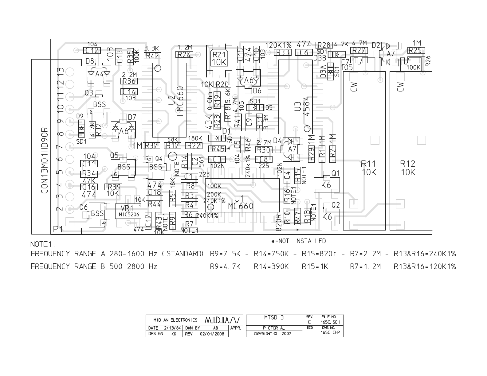
A Tone: Encode the desired A tone to the MTSD-3 at 0.5 to 1.0 V p-p while monitoring TP2 with an oscilloscope.
Turn the pot R-12 until maximum amplitude is obtained. If the pot is turned past the peak then the tone will drop
out. Turn the pot the reverse direction to get the tone back. JU1 should not be installed during the setting of the A
tone. Once aligned cycle the power to the unit and recheck to make certain the amplitude is at maximum.
B Tone: Install JU1 on the MTSD-3. Encode the desired B tone to the MTSD-3 at 0.5 to 1.0 V p-p while
monitoring TP2 with an oscilloscope. Turn the pot R-11 until maximum amplitude is obtained. If the pot is turned
past the peak then the tone will drop out. Turn the pot the reverse direction to get the tone back. Once aligned
cycle the power to the unit and recheck to make certain the amplitude is at maximum. Remove JU1 when
finished.
Long Tone Group Call: Long tone group call can be accomplished by sending 4 seconds of the programmed A
tone, or by programming the A tone and the B tone for the same frequency. This product is not compatible with
Long B tone decode.
3

HARDWARE ALIGNMENT
Bandwidth: If tones A and B are close to one another it may be necessary to narrow the bandwidth of the
decoder by adjusting R-21. With JU1 uninstalled and generating the B tone to the decoder, adjust R-21 to where
U2 Pin 8 does not change from low to high.
Audio Input Level: If there is not enough level going into the decoder it may be necessary to reduce the value of
R-5.
Momentary Output Time: The MTSD-3 gives a 3 second momentary output by default. To increase this time
increase the value of C-9 or decrease the value of R-31 to decrease the time. Please note that this will also affect
the timing of the transpond timing.
Tone Decode Time: The acquisition timing of the MTSD-3 is for 750 msec to 1 second A tone. To lengthen the
time, increase the value of R-25 or decrease the value of R-25 to decrease the time. R-29 controls the acquisition
timing for the B tone and is affected in the same way as R-25.
OPERATION
Decode: Upon decoding of the proper 2-tone sequence the following events will occur:
Momentary Horn Output: The horn output will go low for 3 seconds.
Alert Tone Output: The 2400 Hz alert tone output will generate a tone for 3 seconds.
Transpond Output: The transpond output will go low for 1 second. This is used to activate the PTT of the
radio, so that the alert tone will be sent over the air.
Latched +SQ Output: This line will go from +12 VDC to a float condition.
Latched -SQ Output: This line will go from a ground to a float.
Latched Call Output: This line will go from +12 VDC to ground.
Resetting of Latched Outputs:
Power: Cycling the power off and then back on will reset the outputs.
Monitor Input 1: If this input is used, taking the input from a ground, taken high or to a float, and then
taking this line back to ground will reset the latched outputs.
4

5
TECHNICAL NOTES
2 + 2 Decode: Two MTSD-3 modules can be “anded” together to do 2 + 2 decoding, such as Motorola Quick Call
1 or AvCall. Follow the steps below to set up 2 MTSD-3 modules for 2 + 2 decoding:
1. Lift and isolate the emitter leg of Q3 on the first MTSD-3 from ground.
2. Solder the Horn Output wire (P1-10 Gray/White wire) from the second MTSD-3 to the emitter leg of Q3 on
the first MTSD-3.
3. Connect the Horn Output wire (P1-10 Gray/White wire) on the first MTSD-3 to the desired relay or
equipment.
4.When both units decode simultaneously the ground path is completed and the Horn Output on Unit 1 goes
momentarily (~3 seconds) to ground.
MIDIAN CONTACT INFORMATION
Midian Electronics Inc.
2302 East 22nd Street
Tucson, Arizona 85713 USA
Orders: 1-800-MIDIANS
Phone: 520-884-7981
Fax: 520-884-0422
E-mail: sales@midians.com
Web: http://www.midians.com/

- This page intentionally left blank-


- This page intentionally left blank-


Table of contents
Other Midian Electronics Media Converter manuals

Midian Electronics
Midian Electronics VTE-1 User manual

Midian Electronics
Midian Electronics ANI-F User manual

Midian Electronics
Midian Electronics BTD-1A User manual

Midian Electronics
Midian Electronics TRE-2 User manual

Midian Electronics
Midian Electronics ANI-F Maxon User manual

Midian Electronics
Midian Electronics TS-120-VX1 User manual

Midian Electronics
Midian Electronics TTD-5 User manual