Alke PH-4 Operating manual

Alke BV
Industrielaan 11a
3925 BD Scherpenzeel
The Netherlands
Phone. +31 (0)33 277 38 24
Fax. +31 (0)33 277 30 80
Email: [email protected]
Version: June 2009 Manual number: 0009 0201EN
Users and Installation Manual
Patio Heater PH-4 and PH-8
Bracket mounting for round and square types of parasols with 8 ribs
Chain mounting for pagoda tents or other constructions
GB –IE
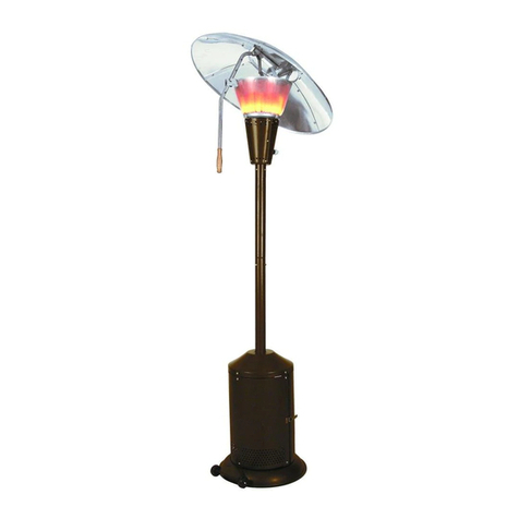
PH-8 SR25
PH-4 DR45
PH-4 SR45C
PH-4 SR45

2
Fig. 1a
Fig. 1b
Fig. 2a
Fig. 2b
Fig. 2c
Fig. 2d
Fig. 2e
Fig. 2f
Fig. 3a
Fig. 3b
Fig. 3c
Fig. 4a

3
Fig. 4b
Fig. 5a
Fig. 5b
Fig. 6
Fig. 7a
Fig. 7b
Fig. 7c
Fig. 7d
Fig. 8a
Fig. 8b
Fig. 8c

4
Fig. 9
Fig. 10
Fig. 11
Fig. 12
Fig. 13
Fig. 14
Fig. 15
Fig. 16
Fig. 17
Fig. 18
Fig. 19
Fig. 20

5
User and Installation manual Patio Heater PH-4 and PH-8
Bracket mounting for round and square types of parasols with 8 ribs
Chain mounting for pagoda tents or other constructions
1. Warnings
Do:
Carefully read the instructions before use and keep the instructions for future reference.
Install this appliance in accordance with the applicable local and national regulations.
Store gas cylinders in accordance with the applicable local and national regulations.
Only use this appliance outdoors or in amply ventilated areas which must have a minimum of 25% of the surface area open.
The surface area is the sum of the walls surface. (see fig. 18, 19, 20)
Use a cylinder isolation valve or a gas valve in the gas line. After use, make sure that the cylinder isolation valve or the gas
valve in the gas line is closed.
Only use the type of gas and the type of cylinder specified by the manufacturer on the data plate and in this instruction.
Shut off the valve at the gas cylinder or gas line first before moving the appliance.
A competent person like a gas installer or other professional shall preferably do first installation.
If the appliance is not safe to use anymore, remove it so that nobody can accidentally operates the appliance. Store the
appliance in a safe place, mark that it cannot be used, and contact a service agent or gas installer to solve the problem.
Install this appliance only in fixed structures or in professional parasols that are placed in a ground mounted support. Tilting of
the parasol shall not be possible. (see fig. 15, 16)
Do not:
Not for domestic use.
Do not use it in basements.
Do not use it below ground level.
Do not use it for heating of habitable areas of domestic premises.
Do not use it in enclosed areas. This can be dangerous and is PROHIBITED. (see fig. 18, 19, 20)
Do not close the parasol while the heaters are still in operation.
Do not move the parasol or the appliance when it is in operation.
Do not use it for other purposes than for space heating only.
Do not use the chain-mounting version into a parasol.
Do not place the gas hose above or before the burners so radiation or combustion gases heats it.
Do not heat the gas hose above 40 degrees Celsius.
2. General information
2.1 Model identification.
The basic model identification is
PH-4 : Parasol Heater with 4 ceramic burner stones up to 5,9 kW (depending gas type)
PH-8 : Parasol Heater with 8 ceramic burner stones up to 10,2 kW (depending gas type)
The following suffixes are used (in combination) to specify the different sub models
SR : Single burner Ring
DR : Double burner Ring
45 : burners mounted under 45 degrees
25 : burners mounted under 25 degrees
C : version adapted for Chain mounting
See the technical table in chapter 10 for the different gas situations.
2.2 Unpacking the appliance.
The carton box will contain the following parts:
1 patio heater PH-4 or PH-8.
1 set of 3 brackets or
1 set containing: chains, S-shaped hooks and 4 hooks with cable straps
1 manual
(optional) gas hose
(optional) gas regulator
Please check the appliance on transportation damage, etc. Before leaving the factory, all the appliances are tested by the manufacturer
on gas for 5 minutes. Therefore, the burners of the appliance will be a little bit discoloured. Check also if the size of brackets is identical
to the rib size of your parasol. The package of the brackets is marked with the dimension of the rib size (width x height). It can be useful
to order extra sets of brackets when you have more parasols. This makes you flexible in selecting which parasol on the terrace will be
the best for heating at that specific moment.
2.3 Working principle of the appliance.
This patio heater gives heat by Infrared radiation. Infrared heating is the only heating principle for an efficient heating comfort in outdoor
situations. It is comparable with sitting in the sun on an early spring day: the air temperature is still low but the radiation of the sun
makes it nice and comfortable.
2.4 Safety in general
This patio heater fully complies with the European Gas Safety requirements. We are proud to say that during prototype testing by an
independent test house, according the European Standards, the emission of safety relevant gases was less than 10% of the maximum
allowable emission.
2.5 Weather conditions
The appliance is made of strong and durable materials. Rain or moisture shall not directly shorten lifetime of the appliance (as long as
the burner stones remain dry) but of course it is better to protect the appliance from these influences. The appliance will not efficiently
work with strong winds. The wind will make ignition difficult or cools down the safety device, which will cut off the gas supply to the
burner. We advice not to use the appliance by wind speeds above 3 m/s (3 Beaufort).

6
3. Installation
3.1 Place of installation
The appliance is intended for outdoor use only or amply ventilated areas and not for indoor heating. (See fig. 18, 19, and 20). When
local regulations allows it, we see no safety objections to use the appliance in large indoor spaces where space and ventilation
conditions are comparable to outdoor use (like exhibition halls, covered shopping streets, etc). First, make a check with your local
authorities in these situations. Never use the appliance in small indoor spaces.
3.2 Safety distance to combustible materials
The appliance produces heat by radiation and by combustion gases. It is important to take the following distances in account from the
burners to combustible materials. This is to avoid fire. Do not use the appliance in situations were the distances to combustibles are
smaller. (See also fig. 17)
Distance
PH-4
PH-8
to the ceiling or parasol clothing
>45 cm
>70 cm
in radiation area of the burners
>70 cm
>100 cm
to side and back
>5 cm
>5 cm
to side walls
>150 cm
>150 cm
to the ground (safety distance for touching the
burners according European standards)
>200 cm
>200 cm
The minimum distance to non combustible materials depends on the specific local situation. Keep in mind that there must be sufficient
free space left letting the combustion gases venting away. Otherwise, they will influence the combustion and proper function of the
appliance. On locations where the combustion gases can vent away easily, we advice a minimum of 30 cm to the ceiling. Note: Be
aware that some non-combustible materials can be subject to discolouring when they become too hot.
3.3 First installation of the appliance on a round parasol, with hooks brackets as in fig. 2a and 2b (not for PH-8)
To carry out the first installation 2 persons are needed. It will take about 10 minutes.
Check if the parasol has 8 ribs. The ribs will make an angle with the parasol of 115 till 140 degrees. The parasol will be of a
round model. On square models these brackets will not work. The appliance is not suitable for parasols with other amount of
ribs. Check also the safety distances to combustible materials.
Check if the parasol is mounted stable and firmly to the ground according the instructions of the parasol manufacturer. It is not
allowed (and dangerous) to mount the appliance in a parasol that falls down easily.
Place the mounting brackets (fig. 2a and 2b) on the ribs of the parasol; place the bolts, rings and nuts. See fig. 3b for the
correct place and position. The bracket with the thread shall have the thread on the right hand (when facing the pole of the
parasol); the brackets with the hook shall have the hook pointing to the pole op the parasol. Do not tighten the nuts too fast. It
should be possible to move the brackets a little bit for adjustment.
One person holds the appliance in place against the ribs of the parasol. The second person screws the brass nut (already
mounted on the appliance) on the bracket with the thread on its side (fig. 4a). Then he moves the other brackets with the
hooks completely around the central burner ring of the appliance (fig. 4b). Tighten the bolts and nuts a bit more so the
appliance will stay in place without help.
Check from a distance if the burner ring is in horizontal position; otherwise move the brackets a bit until they keep the burner
ring in a horizontal position.
Tighten the bolts and nuts of the brackets firmly with a spanner (10 mm) so that the brackets will stay in position, even when a
force is put on it.
Check if the appliance can be removed and replaced easily.
Check if the brackets do not damage parts of the parasol when the parasol is closed.
Connect the appliance to the gas supply and check all connections for gas leaks with soapy water for soundness. (See next
chapters).
Ignite the burners and check for proper operation. (See next chapters).
3.4 First installation of the appliance on parasols, with brackets as in fig. 1a and 1b (PH-8, some models PH-4)
To carry out the first installation 2 persons are needed. It will take about 10 minutes.
Check if the parasol has 8 ribs. The ribs shall make an angle with the parasol of 110 till 138 degrees. The appliance is not
suitable for parasols with other amounts of ribs. Check also the safety distances to combustible materials.
Check if the parasol is mounted stable and firmly to the ground according the instructions of the parasol manufacturer. It is not
allowed (and dangerous) to mount the appliance in a parasol that falls down easily.
Mount to two parts of the brackets for suspension as showed in fig. 1a and turn them to position as showed in fig. 1b.
Place the mounting brackets (fig. 2c and 2d) on the ribs of the parasol; place the bolts, rings and nuts. Do not forget to mount
to adjusting plate on the bracket as showed in fig 2d. See fig. 3a for the correct place and position. The bracket with the
thread shall have the thread on the right hand (when facing the pole of the parasol). Both the suspension brackets (fig. 2c)
shall have the plate with the suspension hole on the side of the bracket with the thread (see fig. 3a). Do not tighten the nuts to
fast. It should be possible to move the brackets a little for adjustment.
One person holds the appliance in place against the ribs of the parasol. The second person moves the hooks on the burner
ring into the holes of the suspension brackets (fig. 5a). Then screw the brass nut (mounted on the appliance already) on the
bracket with the thread on its side (fig. 5b). Tighten the bolts and nuts a bit more so the appliance will stay in place without
help.
Check from a distance if the burner ring is in horizontal position; otherwise move the brackets a bit and adjust the adjusting
plate (fig 2d) until they keep the burner ring in a horizontal position.
Tighten the bolts and nuts of the brackets firmly with a spanner (10 mm) so the brackets will stay in position, even when a
force is put on it.
Check if the appliance can be removed and replaced easily.
Check if the brackets do not damage parts of the parasol when the parasol is closed.
Connect the appliance to the gas supply and check all connections for gas leaks with soapy water for soundness. (See next
chapters).
Ignite the burners and check for proper operation. (See next chapters).

7
3.5 First installation of the appliance in a pagoda tent or other structure (Models with suffix C)
To carry out the first installation 2 persons are needed. It will take about 10 minutes.
Check if the structure or construction of the pagoda tent is strong enough for mounting the appliance. Check also the safety
distances to combustible materials.
Make sure that there is enough ventilation to ventilate the combustion gases away. This is to avoid condensation of water
from the combustion gases and to limit the heat accumulation.
Wrap the cable strap with the hook around the central frame of the pagoda tent or other available construction (see fig. 2e and
2f)
Cut the chains into 8 pieces with a length required in the specific situation and attach the chains to the appliance with the S-
shaped hooks. Attach the other end of the chains to the hooks mounted on the structure (see fig. 3c).
Make sure that the chains are mounted in V-shape as showed in fig. 3c. The burners are now placed in the free space
between the frames. Never place the burners in such a position that the combustion gases heat the frame. Check if the ring is
in horizontal position and adjust if necessary. Close the S-shaped hooks with a pair of pincers.
Attach the gas hose to the frame as showed in fig 3c. Make sure that the gas hose is always in the cold zone between two
burners and never is heated by the combustion gases or radiation heat.
Connect the appliance to the gas supply and check all connections for gas leaks with soapy water for soundness. (See next
chapters).
Ignite the burners and check for proper operation. (See next chapters).
4. Gas supply information
4.1 Gas supply
In case a gas line supplies the gas to the appliance, make sure that an authorised company in your country, in accordance with the local
rules and requirements, makes the system. Always mount a (easy to be reached) gas tap at the end of the gas line. This gas tap is
needed to close the gas supply to the burners to extinguish the flames. In addition, it makes it possible to remove the appliance after
use. For data needed to calculate the dimensions of the gas line, see the technical table.
The gas can also be supplied from butane or propane gas cylinders. The minimum size is a 5 kg cylinder for the PH-4 and 11 kg for the
PH-8. Before buying a cylinder make sure that the connections of the gas regulator and the gas valve of the cylinder are of the same
type. Store the gas cylinder always above the ground in a well-ventilated place. In case the gas cylinder is placed in a cylinder housing,
or cover, make sure that there is enough ventilation as requested by the applicable regulations or standards. Never obstruct these
ventilation holes. The gas cylinder has to be placed under the parasol, directly against the pole of the parasol. In case of pagoda tents,
place the gas cylinder outside the pagoda tent or on sufficient distance from the burners (at least 4 meters) on a place where the
cylinder is protected against radiation heat from the burners. Fasten the gas cylinder to a pole or other structure to make sure that the
cylinder never can turn over. Make sure that the gas cylinder valve can easily be reached to close the gas supply in an emergency
situation. Protect the gas regulator for influences like rain and snow. These can influence proper operation of this device.
Always make sure that the gas pressure and the kind of gas supplied is in accordance with the information on the data plate of the
appliance.
4.2 Gas hose
Make sure that the gas hose never is heated above 40 degrees Celsius. The gas hose must be inspected frequently and must be
changed within the prescribed intervals. Our advice is to check the hose every time the gas cylinder is changed, but at least once a
month. Avoid twisting or stress of the gas hose. Twisting or stress will shorten the live time of the gas hose. During inspection, check the
hose for damage, splitting, ageing and cracking. Pay special attention to the connections. If a defect is seen directly change the gas
hose by a new one of the same type. Some countries have regulations that gas hoses must be replaced every 2 or 3 years. Please
check with your gas supplier. We advice to change the hose every 3 years in case there are no regulations in your country. Always use
official gas hoses. Replace a gas hose always by a type of the same length, internal diameter and equivalent quality. For your own
safety: never use air hoses or water hoses, these are very dangerous for gas transportation! We advice to mount a special safety device
(hose rupture protection device) on the gas cylinder that closes the gas flow as soon as somewhere a gas leak occurs.
As an option (not standard), the gas hose can be delivered with a metal protection around the gas hose. In that case, in addition to the
instructions above we advice a leak test with water every 3 months because inspection is more difficult by the metal protection. Place
the appliance on the ground and connect it to the gas cylinder. Open the gas valve. Submerge the gas hose as far as possible in a
bucket with water and check for bubbles (indicating a gas leak). Check the last part of the gas hose near the gas cylinder and the
appliance with soapy water. Also, check the metal protection for damage. Loose wire ends of the metal protection can hurt people.
Replace the hose in case of leakage or damage.
In some cases the gas hose and gas regulator will not be delivered with the appliance. Contact your local gas supplier to buy these
items. Also he can advice you about the local requirements. Always use locally or nationally approved gas hoses and regulators. Before
buying a gas regulator check the data plate on the appliance to determine which gas, outlet pressure setting and gas consumption of
the regulator is required. The regulator shall be of a non-adjustable type, (except for model PH-8, propane 50-150 mbar).
The minimum length of the hose required under normal installation height in a parasol of 200 cm is 220 cm and shall have an internal
diameter of 8 mm. In case the appliance is mounted in a higher position (or in a pagoda tent), a longer length is required depending your
particular situation. Avoid the unsafe situation where the hose is too long and reached the ground. In that case people can stumble over
the hose or the hose can be easily damaged by other stuff placed on it. Be sure that the gas hose is suitable for LPG gases (or natural
gases, depending the gas selection). We advice to buy a hose already connected to the regulator. Attach the hose to the gas inlet nipple
(8 mm) of the appliance and secure it with a clamp. Before using the appliance, check with soapy water the connection on gas leaks. No
bubbles are allowed to appear.
4.3 Quick connection (optional, not standard)
As an option, a quick connection device is available (only with rubber hoses). The quick connection device makes it possible to
disconnect the gas hose from the appliance. It makes handling and storage easier. When disconnected carefully protect the quick
connection device from dust and dirt. Before disconnecting always close the gas cylinder valve and wait until the burners are
extinguished. Check the quick connection device with the same frequency as the gas hose for leakage and proper function. Check
before each use if the male nipple does not have burrs.
4.4 Changing gas cylinders
Changing or connecting gas cylinders must be done outside, or in an amply ventilated area, in a flame-free environment and away from
other people.
Check if there are no other operating patio heaters, other gas appliances, burning candles or people smoking cigarettes in the
area.

8
Be sure that the valve on the gas cylinder is closed and the burners of the appliance are extinguished.
Unscrew the nut by which the gas regulator is connected to the gas cylinder valve. (Note that most connections are with left-
handed threads. They open in clockwise direction).
Before connecting the (new) gas cylinder, first check if the rubber seals on the cylinder valve or on the regulator-connecting
nut are fitted properly and able to fulfil its function and are not damaged or worn. In that last case do not use it or replace the
seals.
After connecting the regulator firmly, open the cylinder valve and check with soapy water if the connection is leak tight. If
bubbles appear, the connection leaks. Do not use the appliance unless the system is sound. Make sure that the gas cylinder
is securely fixed and never can turn over. Always close the gas valve of empty cylinders while due to temperature raise again
gas can escape.
4.5 What to do by gas leakage
When a gas leak is detected, immediately close the gas supply. Keep open flames away. Do not use the appliance anymore. Contact an
authorised gas technician, gas installer or gas service agent to determine if the gas leakage can be repaired. Never try to do gas repairs
by yourself. Do not use the appliance anymore until the problem is solved.
5. Operation
5.1 How to mount the appliance in a parasol
Open the parasol (with the mounting brackets already in place, see chapter 3)
Take the appliance in both hands and move the opening around the pole of the parasol (fig. 6)
Turn the appliance in such a way that the mounting screw and the bracket with the threaded part are close to each other. (fig.
7a)
Slide the burner ring in the 2 brackets (fig. 7b, 8a) and slide the mounting nut on the bracket with the treaded part (fig. 7c, 8b).
Screw the mounting nut as far as possible on the bracket. When the nut is fully mounted, the thread is visible at the end of the
nut (fig. 7d, 8c)
Connect the gas regulator to the gas cylinder (or connect the gas hose to the gas line).
5.2 How to mount the appliance in a pagoda tent or other structure
Place the hooks on the frame or structure (as showed in fig 2e, 2f and 3c and see also chapter 3.)
Attach the chains of the appliance to the hooks.
Mount the gas hose in a safe way as indicated in chapter 3
Connect the gas regulator to the gas cylinder (or connect the gas hose to the gas line)
5.3 How to operate the appliance
A) Ignition.
Open the valve on the gas cylinder (fig. 9) or open the gas valve in the gas line (fig. 10). Make sure that the appliance ignites
on full pressure in case of a high-low appliance. Cold ignition on low setting is very difficult and sometimes impossible.
Take a (BBQ) lighter or long match and keep the flame under the burner gauze directly on the ceramic burner stone. (Fig. 11,
number 1). Use the ignition hole in the burner gauze situated by the upper burner stone.
Push with your thumb the knob on the safety device. The burner will ignite after a few seconds. (Fig. 11, number 2).
Note: When the appliance is ignited for the first time (or after storage for a period), ignition of the first burner will take some
time because it takes a while before the air in the gas line is replaced by gas. This can be up till 30-60 seconds. The other 3
burners will ignite quickly. Check if both burner stones are ignited.
After ignition, keep the knob in pressed position for about 20 seconds. (Fig. 12).
Release the knob. The burner will stay alight. In case the burner extinguishes directly after releasing the knob, wait for 10
seconds and repeat the ignition procedure. After ignition, a high-low appliance (PH-8 for I3P 50-150 mbar with an adjustable
regulator) can be set on low setting after a preheating time of 3 minutes. This can be done by turning the knob on the
regulator from 10 to a lower number.
Note: All 4 burners must be ignited separately. It is the decision of the user how many burners are ignited, depending the heat demand
at that moment.
Note: A new appliance, used for the first time, sometimes gives a little bit of smoke and smell. Although the burners are cleaned after
production a little bit of remaining protection liquid is causing this. This only happens the first time and stops after a few minutes, when
the appliance is on temperature.
B) How to check correct operation of the burners
Directly after ignition the burner flames are blue (difficult to see during daylight, better to see in the evening or at night). After 1 to 3
minutes, the ceramic burner stone starts glowing and becomes orange. The orange colour shall be evenly spread over the burner
surface. The burner gauze is glowing dark red. The flames will not leave the confines of the burners. The burners shall not make a lot of
noice.
C) Extinguishing.
To extinguish the burners close the gas cylinder valve (fig. 13) or the valve in the gas line (fig. 14). After a few seconds, the flames will
disappear.
Note: It is not possible to extinguish the burners independently of each other. Closing the gas supply is the only way. Then reignite after
3 minutes the amount of burners required at that moment.
Note: After the burners are extinguished, always wait for at least 3 minutes before igniting the burners again. This time is needed by the
safety device to cool down and shut-off the safety valve before re-ignition can be done safely. Not following this rule can create the
unsafe situation that during ignition the flames leave the confines of the burner. (This is a general safety rule world wide for all gas
appliances with thermocouple safety devices).
6 Cleaning, maintenance and servicing
In case the painted surfaces are dirty, they can be cleaned with a moisture cloth and some mild soap. Dust can be removed with a soft
brush. Stainless steel parts can be cleaned with normal domestic stainless steel cleaner. The stainless steel parts of the burners will
discolour a bit by the heat during use. This cannot be removed but has no influence on lifetime or operation of the appliance. The
appliance does not need special daily maintenance and service. We advice at least once a year a maintenance and service check by a
competent gas servicing agent.

9
7 Storage of the appliance and gas cylinders
Always store the appliance in a clean and dry environment. The best way to store is hanging side wards on a hook on the wall. This way
avoids the risk of damaging the burners. Placing the appliance (carefully) side wards resting on the burner reflectors is not advised while
the risk of damage sooner or later is likely. For short-time-storage no further special precautions are needed. For long time storage put a
plastic bag over each burner and close it around the safety device so no dust or insects can enter the appliance. Make sure that the
appliance is cooled down before storing it. Always disconnect the appliance from the gas supply.
Take into account your local requirements for storage of the gas bottles. In most places it is only allowed outside or in a well ventilated
area. Your local fire department or gas supplier can inform you about the regulations.
8 Fault finding
Problem
Action
Burner does not light
- Check if gas valve of the gas cylinder or gas line is open
- Check if gas cylinder is empty
- First ignition will take up to 30-60 seconds before gas is available
- Check if the injector is blocked
- Check if the gas pressure is identical to the pressure indicated on the dataplate
Burner extinguishes after lighting
- Keep button safety device pressed for a longer period (up till 20 seconds)
- Thermocouple or magnetic coil is broken. Contact a gas repair company or gas installer
- Check if both burner stones are ignited.
Flames leave the confines of the burner
or are sooting
- Gas pressure is too high. Check use of correct pressure regulator or check if the gas
pressure regulator is broken.
- Wrong gas is used. Check data plate for the correct gas supply
The burner is only partly glowing
- Wrong gas is used. Check data plate with the gas supply
- Check if the injector or venturi are blocked or dirty
The burner makes a lot of noise after
ignition or after several minutes
- Wrong gas is used. Check data plate with the gas supply
- Check if the burner stone is broken or damaged
The burner ring does not fit anymore
properly in the brackets.
- The parasol is opened in a different position every time. Mark the opening position so that
the parasol will be opened every time in the same way.
9 Declaration of conformity
We, Alke B.V., located in Scherpenzeel, The Netherlands, hereby declare that this product complies with the following EU directives:
Directive on appliances burning gaseous fuels (90/396/EEC)
Scherpenzeel, 05-04-2005
Adri van Alphen Derk Jan Keurhorst
Managing Director Managing Director
For spare parts, service material, advice and information please contact your distributor of this appliance. Service parts are only
available via your distributor. For general manufacturers information please see the internet: www.alke.nl
10 Technical table (see next page)
First read the technical table to find the references to the remarks written below.
(*) Weight is the standard SR model inclusive mounting brackets but without hose and gas regulator. For the DR model add another 2,5
kg.
(**) The combination category, gas supply pressure and countries of destination are selected for the European standards EN 14543, EN
461 and EN 437. These standards give the official situation per country. But their listing is not always complete and sometimes unclear
and in contradiction with each other. In some countries the situation locally can be different from the official information or the
information is even not available. Our advice is to stay first with the official listing as given in the table above. In other cases, check with
your local gas authorities the data plate of the appliance to determine if the appliance can be used safely in your specific situation.
(***) Not specified as a standard pressure, but until now all countries accept this as long as the regulator is supplied with the appliance.
Product Identification Number CE approval (issued by Gastec Certification BV): PIN: 0063BO3251
(stamp dealer)

10
Please check first the data plate on your appliance to check which category your appliance is made for. Find below the technical data per category.
Model
Category
Gas Supply
pressure
Gas
Heat input (Qn)
Gas
Consumption
Injector
Venturi
Weight
(*)
Dimension
Countries of destination (**)
(cat)
(p)
Hs (gross)
Hi (nett)
(gr/h, m3/h)
Diam. x height
PH-4
I2L
25 mbar
G25 (natural gas)
1,47 –5,90 kW
1,32 –5,30 kW
0,64 m3/h
0,88 mm
No
5,7 kg
91 x 16 cm
NL
PH-4
I2H
20 mbar
G20 (natural gas)
1,47 –5,90 kW
1,32 –5,30 kW
0,54 m3/h
0,85 mm
No
5,7 kg
91 x 16 cm
AT, BE, BG, CH, CZ, DK,
ES, FI, FR, GB, GR, IE, IT,
LU, PT, RO, SE
I2E
20 mbar
G20 (natural gas)
1,47 –5,90 kW
1,32 –5,30 kW
0,54 m3/h
0,85 mm
No
5,7 kg
91 x 16 cm
I2E+
20/25 mbar
G20/G25 (natural gas)
1,47 –5,90 kW
1,32 –5,30 kW
0,54 m3/h
0,85 mm
No
5,7 kg
91 x 16 cm
PH-4
I2ELL (E)
20 mbar
G20 (natural gas)
1,47 –5,90 kW
1,32 –5,30 kW
0,54 m3/h
0,85 mm
No
5,7 kg
91 x 16 cm
DE
I2ELL (LL)
20 mbar
G25 (natural gas)
1,47 –5,90 kW
1,32 –5,30 kW
0,64 m3/h
0,94 mm
No
5,7 kg
91 x 16 cm
PH-4
I3P
30 mbar
G31 (LPG-propane)
1,15 –4,60 kW
1,05 –4,25 kW
335 gr/h
0,56 mm
No
5,7 kg
91 x 16 cm
AT, BE, CH, CZ, DE, ES,
FR, GB, GR, IE, LU, NL, PT
I3P
37 mbar
G31 (LPG-propane)
1,25 –5,10 kW
1,15 –4,70 kW
370 gr/h
0,56 mm
No
5,7 kg
91 x 16 cm
I3P
50 mbar
G31 (LPG-propane)
1,45 –5,90 kW
1,35 –5,40 kW
425 gr/h
0,56 mm
No
5,7 kg
91 x 16 cm
PH-4
I3B/P
50 mbar
G30/G31 (LPG-butane/propane)
1,35 –5,50 kW
1,25 –5,10 kW
400 gr/h
0,50 mm
No
5,7 kg
91 x 16 cm
AT, CH, DE, RO, BE
PH-4
I3B/P
30 mbar
G30/G31 (LPG-butane/propane)
1,20 –4,80 kW
1,10 –4,40 kW
350 gr/h
0,54 mm
No
5,7 kg
91 x 16 cm
DK, FI, GR, IS, IT, NO, PT,
RO, SE
I3+
28-30/37 mbar
G30/G31 (LPG-butane/propane)
1,20 –4,80 kW
1,10 –4,40 kW
350 gr/h
0,54 mm
No
5,7 kg
91 x 16 cm
I3B
30 mbar
G30 (LPG-butane)
1,20 –4,80 kW
1,10 –4,40 kW
350 gr/h
0,54 mm
No
5,7 kg
91 x 16 cm
PH-8
I2L
25 mbar
G25 (natural gas)
2,55 –10,2 kW
2,30 –9,20 kW
1,13 m3/h
1,20 mm
15 mm
10,8 kg
119 x 21 cm
NL
PH-8
I2H
20 mbar
G20 (natural gas)
2,55 –10,2 kW
2,30 –9,20 kW
0,97 m3/h
1,17 mm
18 mm
10,8 kg
119 x 21 cm
AT, BE, BG, CH, CZ, DK,
ES, FI, FR, GB, GR, IE, IT,
LU, PT, RO, SE
I2E
20 mbar
G20 (natural gas)
2,55 –10,2 kW
2,30 –9,20 kW
0,97 m3/h
1,17 mm
18 mm
10,8 kg
119 x 21 cm
I2E+
20/25 mbar
G20/G25 (natural gas)
2,55 –10,2 kW
2,30 –9,20 kW
0,97 m3/h
1,17 mm
18 mm
10,8 kg
119 x 21 cm
PH-8
I2ELL (E)
20 mbar
G20 (natural gas)
2,55 –10,2 kW
2,30 –9,20 kW
0,97 m3/h
1,17 mm
18 mm
10,8 kg
119 x 21 cm
DE
I2ELL (LL)
20 mbar
G25 (natural gas)
2,55 –10,2 kW
2,30 –9,20 kW
1,13 m3/h
1,27 mm
15 mm
10,8 kg
119 x 21 cm
PH-8
I3P
50-150 mbar
G31 (LPG-propane)
2,40 –9,50 kW
2,20 –8,75 kW
680 gr/h
0,54 mm
12,5 mm
10,8 kg
119 x 21 cm
(***)
PH-8
I3P
30 mbar
G31 (LPG-propane)
1,90 –7,60 kW
1,75 –7,00 kW
545 gr/h
0,72 mm
15 mm
10,8 kg
119 x 21 cm
BE, CZ, ES, FR, GB, IE,
NL, PT
I3P
37 mbar
G31 (LPG-propane)
2,10 –8,40 kW
1,95 –7,80 kW
600 gr/h
0,72 mm
15 mm
10,8 kg
119 x 21 cm
PH-8
I3P
50 mbar
G31 (LPG-propane)
2,35 –9,40 kW
2,10 –8,40 kW
675 gr/h
0,70 mm
15 mm
10,8 kg
119 x 21 cm
AT, BE, CH, DE, ES FR,
GB, LU, NL
PH-8
I3B/P
50 mbar
G30/G31 (LPG-butane/propane)
2,30 –9,20 kW
2,10 –8,40 kW
670 gr/h
0,66 mm
17 mm
10,8 kg
119 x 21 cm
AT, CH, DE, RO, BE
PH-8
I3B/P
30 mbar
G30/G31 (LPG-butane/propane)
1,75 –7,00 kW
1,60 –6,40 kW
510 gr/h
0,66 mm
17 mm
10,8 kg
119 x 21 cm
DK, FI, GR, IS, IT, NO, PT,
RO, SE
I3+
28-30/37 mbar
G30/G31 (LPG-butane/propane)
1,75 –7,00 kW
1,60 –6,40 kW
510 gr/h
0,66 mm
17 mm
10,8 kg
119 x 21 cm
I3B
30 mbar
G30 (LPG-butane)
1,75 –7,00 kW
1,60 –6,40 kW
510 gr/h
0,66 mm
17 mm
10,8 kg
119 x 21 cm

Alke BV
Industrielaan 11a
3925 BD Scherpenzeel
The Netherlands
Phone. +31 (0)33 277 38 24
Fax. +31 (0)33 277 30 80
Email: [email protected]
Version: June 2009 Manual number: 0009 0201EN
This manual suits for next models
1
Table of contents
