manuals.online logo
Brands
  1. Home
  2. •
  3. Brands
  4. •
  5. WilTec
  6. •
  7. Patio Heater
  8. •
  9. WilTec 63021 User manual

WilTec 63021 User manual

User’s manual
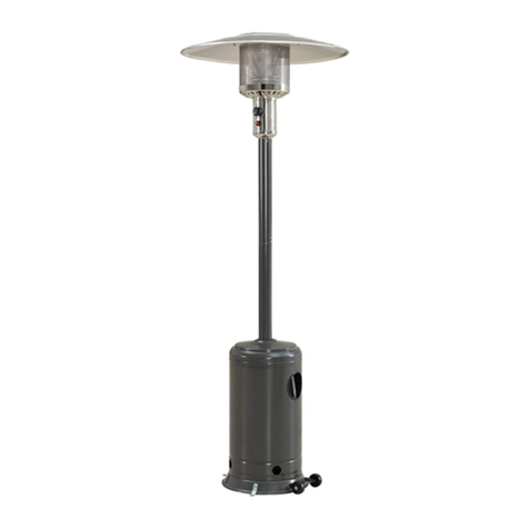
Patio Heater 13,000 W
63021
Illustration similar, may vary depending on model
Please read and follow the operating instructions and safety information prior to initial operation.
Technical changes reserved!
Illustrations, functional steps, and technical data may deviate insignificantly due to continuous further
developments.
© by WilTec Wildanger Technik GmbH Item 63021 Page 2
http://www.WilTec.de
http://www.aoyue.eu 01 2022-1
http://www.teichtip.de
The information contained in this document may alter at any time without prior notice. No part of this
document may be copied or otherwise duplicated without prior written consent. All rights reserved.
WilTec Wildanger Technik GmbH cannot be held liable for any possible mistakes in this operating man-
ual, nor in the diagrams and illustrations shown.
Although WilTec Wildanger Technik GmbH has made every possible effort to ensure that this operating
manual is complete, accurate, and up-to-date, errors cannot be ruled out entirely.
If you have found an error or wish to suggest an improvement, we look forward to hearing from you.
Send us an e-mail to:
[email protected]
or use our contact form:
https://www.wiltec.de/contacts/
The most recent version of this manual in several languages can be found in our online shop:
https://www.wiltec.de/docsearch
Our postal address is:
WilTec Wildanger Technik GmbH
Königsbenden 12
52249 Eschweiler Germany
Do you wish to collect your goods? Our address for collection is:
WilTec Wildanger Technik GmbH
Königsbenden 28
52249 Eschweiler Germany
In order to shorten the waiting time and to allow for an easy on-site processing, we kindly ask you to
contact us briefly beforehand or to place your order via the webshop.
E-mail: service@wiltec.info
Tel: +49 2403 55592–0
Fax: +49 2403 55592–15
To return your goods for exchange, repair, or other purposes, please use the following address. Atten-
tion! To allow for a trouble-free complaint or return, it is important to contact our customer service team
before returning your goods.
Retourenabteilung
WilTec Wildanger Technik GmbH
Königsbenden 28
52249 Eschweiler Germany
E-mail: service@wiltec.info
Tel: +49 2403 55592–0
Fax: +49 2403 55592–15
© by WilTec Wildanger Technik GmbH Item 63021 Page 3
http://www.WilTec.de
http://www.aoyue.eu 01 2022-1
http://www.teichtip.de
Introduction
Thank you for choosing to purchase this quality product. To minimise the risk of injury, we ask you to
always take some basic safety precautions when using this product. Please read this operating manual
carefully and make sure that you understand it.
Keep these operation instructions in a safe place.
Safety instructions
Attention:
When you smell gas:
•close gas supply.
•extinguish open flames.
•With gas smell persisting, immediately call gas supplier and fire brigade.
•Never store or use petrol or other highly flammable vapours and liquids near this device or
similar devices.
•A disconnected liquid gas cylinder must not be stored near this device or comparable devices.
•Only suitable for outdoor use or in very well-ventilated areas. In such an area, at least a quarter
of its total surface must be open. The total surface of an area is the total of its wall surfaces.
•Improper installation, adjustment, structural changes, maintenance, or care can cause property
damage or injuries. Read the assembly, operation, and maintenance instructions carefully and
completely before you start using the device.
•The device and gas cylinder must be set up in accordance with the applicable regulations.
•The ventilation slots in the gas cylinder housing must not be blocked.
•The device must not be moved while in operation.
•Gas lines and hoses must be replaced within the prescribed periods.
•Only gas and gas cylinders corresponding to the manufacturer’s instructions may be used.
•A space with a maximum diameter of 29 cm and a height of 70 cm is available in the heater for
the gas cylinder (not included in the scope of delivery). In strong winds, special care must be
taken to ensure that the heater cannot fall over. The distance between the device and the gas
cylinder must be at least 1 m.
•The injector of this device cannot be removed, it is only connected at the factory. It is forbidden
to modify the device in such a way that it works at a pressure other than the set pressure.
•Do not connect the gas cylinder directly to the device without interposing a pressure reducing
valve. Only use the gas and the type of gas cylinder specified in the instructions.
•The pressure reducing valve must match the respective device type in accordance with DIN
EN16129:2013 and national standards:
◦A 30 mbar pressure reducing valve is used for butane/propane of category I3BP(30).
◦A 30 mbar pressure reducing valve is used for butane of category I3+(28–30/37).
◦A 37 mbar pressure reducing valve is used for propane of category I3+(28–30/37).
© by WilTec Wildanger Technik GmbH Item 63021 Page 4
http://www.WilTec.de
http://www.aoyue.eu 01 2022-1
http://www.teichtip.de
◦A 50 mbar pressure reducing valve is used for butane/propane of category I3B/P(50).
◦We recommend the use of a gas hose in accordance with DIN EN16436:2014.
Safety of use
•Carefully read the instructions to ensure that
◦the gas cylinder valve is only is replaced in a very well-ven-
tilated area and away from sources of ignition such as can-
dles, cigarettes, etc.;
◦the pressure reducing valve seal is checked for proper seat-
ing and readiness for use (see drawing);
◦the ventilation slots in the gas cylinder housing are not
blocked;
◦after use, the gas supply is switched off at the gas cylinder valve;
◦the device is not put into operation when a gas leak occurs or, if it is already in operation,
the gas supply is switched off, the device is checked thoroughly, and any damage is re-
paired before it is used again;
◦the gas hose is checked at least once a month, but every time the gas cylinder is replaced
or after a long period of non-use, and that, if there are signs of breaks, cracks or other signs
of wear and tear, it is replaced with a new hose of the same length and quality;
◦the device is not used in closed rooms; such use is dangerous and therefore PROHIBITED!
•The heater is not suitable for use on recreational vehicles and/or boats.
•The heater should only be installed and connected by a specialist.
•Do not try to modify the device in any way.
•Replace the pressure reducing valve only with a factory-suggested replacement valve.
•Do not use petrol or other flammable vapours or liquids in the device.
•Before commissioning, the entire gas line system, the hoses, the pressure reducing valve, and
the pilot flame/burner must be checked for leaks or damaged areas.
•The leak test should be carried out with a soap solution. Never use an open flame to look for
leaks.
•Do not put the heater into operation until you have checked all connections for leaks.
•Immediately close the gas valve if you smell gas. If the connection between the hose and the
pressure reducing valve is leaking, tighten it again and carry out another leak test. If bubbles
continue appearing, contact the hose vendor. If the connection between the pressure reducing
valve and the valve of the gas cylinder is leaking, loosen it, re-tighten it, and check it again for
leaks. If bubbles still form after several tests, the gas cylinder valve is defective and must be
returned to the seller.
•Do not move the heater when it is in operation. After taking it out of operation, do not move it
until it has cooled down.
•Make sure that the ventilation slots are not blocked. Remove debris.
•Do not paint the hat, the protective grille, or the control panel.
•Check the setting unit, the burner, and the ventilation ducts for cleanliness. If necessary, they
must be cleaned regularly.
•The liquid gas tank must be closed when the radiant heater is not in operation.
•Check the radiant heater immediately if one of the following events has occurred:
◦the heater does not reach the set temperature,
◦the burner makes a knocking noise when it is in operation (but a slight noise when the
burner is switched off is normal),
◦a smell of gas in conjunction with extreme yellowing of the tip of the burner flame.
•The assembly of pressure reducing valve and hose must not be in the path of people. Care
must be taken to prevent someone from tripping over it or over something nearby so that the
hose is not accidentally damaged.
Personal safety
•Do not use the heater indoors; otherwise, there is a risk of property damage or injury.
•Improper assembly, settings, or structural changes can result in property damage or injuries.
© by WilTec Wildanger Technik GmbH Item 63021 Page 5
http://www.WilTec.de
http://www.aoyue.eu 01 2022-1
http://www.teichtip.de
•Adults and children must not come too close to the very hot surfaces of the radiant heater so
that they do not get burned and so that their clothing does not catch fire.
•Children near the radiant heater must be carefully supervised.
•Clothing or other flammable materials must not be hung on or near the heater.
Safety during repair and maintenance
•The heater should only be repaired by a specialist.
•Put a protective device that has been removed for maintenance purposes back on before re-
starting the heater.
Assembling and locating the heater
•The heater may only be used in outdoor areas and only in places where a
sufficient supply of fresh air can be ensured.
•Make sure that there is sufficient space around the heater, i.e., 100 cm up-
wards and on all sides.
•The heater must be set up on a level and firm surface.
•Never operate the heater in potentially explosive environments, e.g., where
petrol or other highly flammable liquids or vapours are stored.
•To prevent the heater from falling over in strong winds, its base must be
screwed to the ground.
Gas requirements
•Only use propane or butane gas.
•The assembly of pressure reducing valve and hose must correspond to the local regulations.
•The installation must also comply with local requirements; if there are none, it must meet the
standard requirements for the storage and treatment of liquefied gases.
•If the gas container is dented, rusted, or damaged, it should be checked by the seller of the gas
cylinder. It can be very dangerous in this condition. Never use a gas container with a damaged
valve connection.
•The propane gas tank must be set up in such a way that the vapours generated by the gas
bottle can escape.
•Never connect a propane gas tank to the heater without also using a pressure reducing valve.
Leakage test
The gas connections attached to the heater are checked for leaks before shipping. However, a full leak
test must also be carried out at the installation site, as damage may have occurred during transport due
to improper handling or excessive pressure.
•Make a soap solution from one part liquid soap and one part water. This soap solution can be
applied with a spray bottle, a brush, or a scrap of cloth. If there is a leak, bubbles will appear.
•The heater must be checked for leaks when the gas bottle is full.
•Make sure that the safety valve is in the OFF position.
•Turn on the gas supply.
•If a leak is found, the gas supply must be switched off again. Tighten any leaky connections,
turn on the gas supply and check the tightness again.
•Never smoke during a leak test.
© by WilTec Wildanger Technik GmbH Item 63021 Page 6
http://www.WilTec.de
http://www.aoyue.eu 01 2022-1
http://www.teichtip.de
Operation and storage
Turning on the heater
1. Turn the valve on the gas bottle fully open.
2. Press the rotary control switch and turn it counter-clockwise to “PILOT.”
3. Press the rotary control switch in and hold it down for 90 s. Meanwhile, press the ignition switch
several times until a pilot flame starts to burn. Release the rotary control switch when the flame
burns.
Notes:
◦If a new gas container has been connected, wait at least one minute until the air in the gas
line has escaped.
◦When igniting the pilot flame, make sure that the rotary control switch is held down the entire
time you operate the ignition switch. When the burns, the rotary control switch can be re-
leased again.
◦The pilot flame can be observed and checked through the small round window; to do this,
the cover at the lower end of the flame protection grille must be pushed to the side (to the
left or right of the control unit).
◦If the pilot flame does not ignite or goes out again, repeat step 3.
4. After igniting the pilot flame, turn the rotary control switch to the highest setting for 5 min; then
you can set it to the temperature desired.
Turning out the heater
1. Set the rotary control switch to “PILOT.”
2. Press the rotary control switch and turn it to “OFF.”
3. Completely close the valve on the gas bottle.
Storage
1. Close the gas cylinder valve after use or in the event of a malfunction.
2. Remove the pressure reducing valve and the gas hose.
3. Check the gas valve for leaks and damage. If you suspect damage, have the seller replace it.
4. Never store LPG cylinders in basements or in places without adequate airflow.
Cleaning and care
•Wipe powder-coated surfaces with a soft, damp cloth. Do not clean the heater with flammable
or corrosive cleaning agents.
•Remove debris from the burner to keep it clean and safe to use.
© by WilTec Wildanger Technik GmbH Item 63021 Page 7
http://www.WilTec.de
http://www.aoyue.eu 01 2022-1
http://www.teichtip.de
Main components and their name
№
Name
1
Reflector
2
Flame screen
3
Burner base
4
Air admittance fence
5
Gas valve controller
6
Base of control housing
7
Post
8
Tank housing
9
Post bracket
10
Stand
Construction and characteristics
•Portable patio/garden heater with gas container housing
•Housing made of powder-coated steel or stainless steel
•Gas hose connections with metal hose clamps (screw caps for Germany)
•Heat radiation from reflector
Technical specifications
Gas to be used
only propane, butane, or their mixture
Max. power (W)
13,000
Min. power (W)
5,000
Consumption
Category
Gas type
Gas pressure (m㍴)
Outlet pressure of regula-
tor (m㍴)
I3+ (28–30/37)
Butane
28–30
30
Propane
37
37
I3B/P (30)
Butane, propane, or
their mixtures
30
30
I3B/P (50)
50
50
I3B/P (37)
37
37
© by WilTec Wildanger Technik GmbH Item 63021 Page 8
http://www.WilTec.de
http://www.aoyue.eu 01 2022-1
http://www.teichtip.de
Always use the pressure reducing valve corresponding to the above-mentioned outlet pressure.
Injectors
Category
Gas type
Gas pressure
(mbar)
Total heat input
(heating value HS :
rated power QN) (㎾)
Injector size (㎜)
I3+(28–30/37)
Butane
28–30
13
(G30: 945 g⁄h;
G31: 929 g⁄h)
1.90 (main burner)
0.18 (pilot burner)
Propane
37
I3B/P(30)
Butane, propane,
or their mixtures
30
I3B/P(50)
50
1.70 (main burner)
0.18 (pilot burner)
I3B/P(37)
37
1.80 (main burner)
0.18 (pilot burner)
•The information on the injector, e.g., “1.90,” indicates the injector size, e.g., 1.90 mm.
•The gas hose and pressure reducing valve must comply with local regulations.
•The device requires a 1.4 m long approved hose.
© by WilTec Wildanger Technik GmbH Item 63021 Page 9
http://www.WilTec.de
http://www.aoyue.eu 01 2022-1
http://www.teichtip.de
Main components
Tools needed
•10 mm and 13 mm open end wrench
•20 cm adjustable spanner (2)
•23 cm slip joint pliers
•Philips screwdriver with medium blade
•Spray bottle of soap solution for leak test
Figures
№
Name
Qty.
A
Reflector panel
3
B
Reflector plate
1
FF
Reflector stud
3
C
Head assembly
1
F
Gas hose
1
D
Gas cylinder housing
1
E
Post
1
G
Post bracket
3
H
Stand
1
I
Wheel kit
1
© by WilTec Wildanger Technik GmbH Item 63021 Page 10
http://www.WilTec.de
http://www.aoyue.eu 01 2022-1
http://www.teichtip.de
Hardware contents
M8 flange nut
(2×)
M8×16 bolt (5×)
M6 flange nut
(6×)
Stainless steel
bolt (4×)
M6×30 bolt
(6×)
Reflector
spacer (3×)
⌀8 washer (9×)
⌀6 washer (9×)
M6×10 screw
(9×)
Cap nut (9×)
Wing nut (3×)
Wrench (1×)
Assembly
Step 1:
1. Put the 3 post brackets on each position on the
stand as shown.
2. Use 3 M8×16 bolts for connecting.
Step 2:
1. Put the post on the top of the post brackets.
2. Use 6 large M6 bolts and counter-nuts to con-
nect the post to the post brackets. Tighten the bolts
and nuts.
© by WilTec Wildanger Technik GmbH Item 63021 Page 11
http://www.WilTec.de
http://www.aoyue.eu 01 2022-1
http://www.teichtip.de
Step 3:
Put the gas cylinder housing over the post from
above and place it on the stand.
Step 4:
1. Remove the 4 bolts from the burner.
2. Push the gas hose through the post from above.
3. Fix the burner unit to the post by the 4 bolts.
Step 5:
1. Check if the connection of the post and burner
are assembled according to instructions, and all
bolts and nuts are tightened.
2. Put 6 large flat washers on the 3 reflector spac-
ers.
Step 6:
Fasten the reflector with 3 large flat washers and
3wing nuts.
© by WilTec Wildanger Technik GmbH Item 63021 Page 12
http://www.WilTec.de
http://www.aoyue.eu 01 2022-1
http://www.teichtip.de
Step 7:
1. Lift the gas cylinder housing and place it on the
post bracket.
2. Connect the end thread of the inlet gas hose to
the pressure reducing valve.
3. Connect the pressure reducing valve to the gas
container and tighten with an adjustable wrench.
4. Place the liquid gas container on the stand.
5. Fasten the gas cylinder with the strap.
Troubleshooting
Problem
Possible cause
Proposed solution
Pilot flame does not ignite.
Gas valve closed
Open gas valve.
Fuel used up
Refill fuel.
Opening clogged
Clean or replace opening.
Air in the gas hose system
Let air out of the lines.
Lose connections
Re-tighten connections.
Pilot flame does not stay on.
Deposits on pilot flame
Clean contaminated areas.
Lose connections
Re-tighten connections.
Defective heat sensor
Replace heat sensor.
Leaking gas line
Check connections.
Insufficient fuel pressure
Container almost empty; refill.
Burner does not light.
Insufficient fuel pressure
Container almost empty; refill or
replace.
Opening clogged
Clean or replace opening.
Control not on.
Turn valve to On.
Defective heat sensor
Replace heat sensor.
Pilot light unit bent
Properly place pilot light unit.
Not in correct location
Position properly and retry.
If the device shows any errors during assembly or use, do not try to modify it, but contact the seller.
© by WilTec Wildanger Technik GmbH Item 63021 Page 13
http://www.WilTec.de
http://www.aoyue.eu 01 2022-1
http://www.teichtip.de
Regulations for waste disposal
The Waste Electrical and Electronic Equipment Directive (WEEE Directive, 2012/19/EU) of the EU was
implemented in the German law related to electrical and electronic equipment and appliances.
All WilTec electric devices that fall under the WEEE directive are labelled with the symbol of a crossed-
out wheeled rubbish bin. This symbol indicates that this electric device must not be disposed of with the
domestic waste.
WilTec Technik GmbH is registered with the German registration authority EAR (Stiftung Elektro-
Altgeräte Register) under the WEEE-registration number DE45283704.
Disposal of used electrical and electronic devices (in-
tended for use in the countries of the European Union
and other European countries with a separate waste
collection system for these devices).
The symbol on the packaging or the product itself indi-
cates that this product must not be treated as normal
domestic waste but must be disposed of at a recycling
collection station for electrical and electronic waste.
By disposing of this product correctly, you contribute to
the protection of the environment and the health of your
fellow people. Inappropriate disposal threatens the en-
vironment and health.
Material recycling helps to reduce the consumption of raw materials.
Additional information about the recycling of this product can be provided by your local commune, the
municipal waste disposal facilities, or the store where you purchased the product.
Address:
WilTec Wildanger Technik GmbH
Königsbenden 12 / 28
52249 Eschweiler Germany
Important Note:
Reproduction and any commercial use (of parts) of this operating manual, requires a written permission
of WilTec Wildanger Technik GmbH.

Other manuals for 63021

1

Other WilTec Patio Heater manuals

WilTec 63021 User manual

WilTec

WilTec 63021 User manual

WilTec 61988 User manual

WilTec

WilTec 61988 User manual

Popular Patio Heater manuals by other brands

Sunred RD-SILVER-3000W manual

Sunred

Sunred RD-SILVER-3000W manual

Alpina Bali EH900 instruction manual

Alpina

Alpina Bali EH900 instruction manual

Princess auto PH05-S Assembly and operation instructions

Princess auto

Princess auto PH05-S Assembly and operation instructions

Silverline COMFORT 880 manual

Silverline

Silverline COMFORT 880 manual

Thermo THI 2000 Safety instructions and operation manual

Thermo

Thermo THI 2000 Safety instructions and operation manual

SunGlo A242 Installation, operation and maintanance manual

SunGlo

SunGlo A242 Installation, operation and maintanance manual

Blumfeldt Heat Guru Plus In&Out manual

Blumfeldt

Blumfeldt Heat Guru Plus In&Out manual

Sunwood MARINO Instruction, Operation and Installation Manual Addendum

Sunwood

Sunwood MARINO Instruction, Operation and Installation Manual Addendum

Four Seasons Courtyard SRFP41305 quick start guide

Four Seasons Courtyard

Four Seasons Courtyard SRFP41305 quick start guide

Dyna-Glo DGPH301BL owner's manual

Dyna-Glo

Dyna-Glo DGPH301BL owner's manual

Maxxtools PH09-S-P instruction manual

Maxxtools

Maxxtools PH09-S-P instruction manual

HEAT1 ECO high-line LDHR033-120KY instructions

HEAT1

HEAT1 ECO high-line LDHR033-120KY instructions

Blooboost 545150014 manual

Blooboost

Blooboost 545150014 manual

Endless Summer 200209 owner's manual

Endless Summer

Endless Summer 200209 owner's manual

Hortus Golden Tube instructions

Hortus

Hortus Golden Tube instructions

Blumfeldt Heatbell manual

Blumfeldt

Blumfeldt Heatbell manual

nedis HTPA21BKW Safety instruction

nedis

nedis HTPA21BKW Safety instruction

Omcan PH-CN-2210-S instruction manual

Omcan

Omcan PH-CN-2210-S instruction manual

manuals.online logo
manuals.online logoBrands
  • About & Mission
  • Contact us
  • Privacy Policy
  • Terms and Conditions

Copyright 2025 Manuals.Online. All Rights Reserved.