All American Scoreboards emc 8000 Series User manual

rev. 10/11/2010
Controlling your Everbrite Message Center with
an All American Scoreboards 8000 Series Console
emc
everbrite message center
Requires Firmware Version 5.06+

NOTE:
Table of Contents
1.0 8000 Series Multi-Sport Console ................................................................................................................... 3
1.1 Console Backplate ........................................................................................................................................................................... 3
1.2 Console LCD ...................................................................................................................................................................................... 4
1.3 Console Keypad ............................................................................................................................................................................... 5
2.0 EMC SIGN SETUP ............................................................................................................................................. 6
2.1 EMC Denitions ............................................................................................................................................................................... 6
2.2 Password Protection ...................................................................................................................................................................... 7
2.3 Time and Date .................................................................................................................................................................................. 9
3.0 EDIT MESSAGES ............................................................................................................................................ 10
3.1 Line Transition Modes .................................................................................................................................................................11
4.0 EDIT PROGRAMS ........................................................................................................................................... 13
5.0 PLAY MODE ................................................................................................................................................... 14
6.0 PLAY & EDIT MODE QUICK REFERENCE GUIDE ........................................................................................... 15
7.0 Firmware Update / Computer Interface / Backup Messages ..................................................................... 16
8.0 Safety ............................................................................................................................................................. 19
9.0 Warranty ........................................................................................................................................................ 20
10.0 Technical Support ....................................................................................................................................... 21
9.1 Customer Service ...........................................................................................................................................................................21
9.2 Contact Information ......................................................................................................................................................................21
2
TABLE OF
CONTENTS
Manual Overview
This manual is intended for the use of the All American Scoreboard owners and users. Read this manual carefully before
starting the equipment.
This manual contains important information for operation and maintenance of the equipment. It also contains important
instructions to prevent accidents, personal injury and/or serious damage prior to or during operation of the equipment.
Familiarize yourself thoroughly with the function and operation of this equipment and strictly observe the directions given.
If you have any questions or need further details on specic aspects related to the AAS system, please do not hesitate to
contact us.
In this manual you will nd three levels of agged notes or warnings.
WARNING!
CAUTION!
3
STORING:
Battery should be fully charged when storing, and should be kept at room temperature.
Recharging once every 30 to 45 days of storage is recommended. If batteries are stored
longer, it may take two or three cycles before full run time is restored.
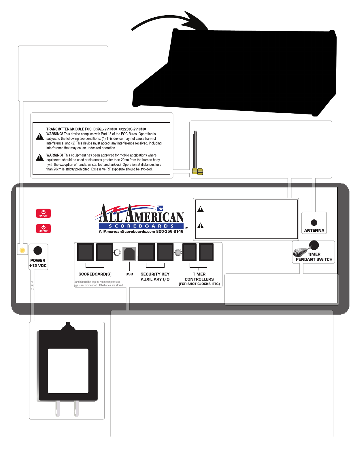
The 8000 Console Backplate.
WARNING! This equipment has been approved for mobile applications where
equipment should be used at distances greater than 20cm from the human body
(with the exception of hands, wrists, feet and ankles). Operation at distances less
than 20cm is strictly prohibited. Excessive RF exposure should be avoided.
Setup Instructions:
Press once to turn on.
Follow prompts on screen.
Press and hold to turn off.
TRANSMITTER MODULE FCC ID:KQL-PKLR2400-200 IC:22683911808A3 17
WARNING! This device complies with Part 15 of the FCC Rules. Operation is
subject to the following two conditions: (1) This device may not cause harmful
interference, and (2) This device must accept any interference received, including
interference that may cause undesired operation.
RJ45 RJ45 RJ45 RJ45 RJ11 RJ11
Radio Controlled Units Only
Radio Antenna
Radio Antenna screws into the backplate
above the Timer Pendant Switch.
For best results, aim antenna straight up to
the ceiling or sky - do not aim directly at
scoreboard.
AC Adapter
Plug the
supplied 12VDC
adapter into a
standard
115VAC outlet.
Scoreboards
For hard-wired models only, plug the scoreboard(s) into the console using
an RJ45 connector. Plug in all hard-wired scoreboards, shot clocks, delay of
game timers, segment timers and stat panels here.
Security Key | Auxiliary I/O
Used to connect consoles together for use with stat panels, etc.
Timer Controllers
Plug in seperate All American consoles that control shot clocks, delay of
game timers, etc here using an RJ11 connector.
USB (Console V4.00+ Only)
Connect to a computer to update console version and advanced console
setup functionality.
Pendant Switch
Plug in the pendant switch to bypass
the start/stop key for the timer.
Adapter LED
Orange = Adapter is good.
Red = Adapter supplies
enough power to run, but not
enough to charge the battery.
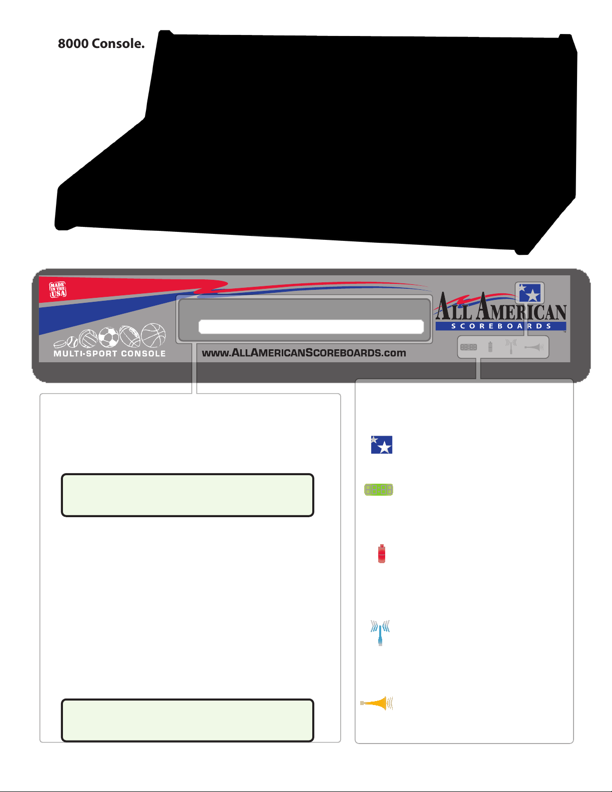
The 8000 Console.
LED Windows
Displays crucial troubleshooting and
functional information at a glance.
Power.
Clock.
Stars turn white when console is turned on.
The clock LED is not used in Message Mode, but
will flash with all LEDs when the battery is low.
Battery.
Battery symbol displays a constant red when
charging a battery. Battery symbol turns green
or turns off when charged for 3 hours.
Wireless.
Wireless symbol will light blue when a radio is
connected.
Horn (Message Received).
The “Horn” LED will flash twice when it receives
confirmation from each EMC.
LCD Window
Displays all information needed to navigate through sign
setup, messages and programs.
Typical Gameplay Display
Low Battery Display
Low battery message in the lower part of display and all
LEDs will flash when battery time is below 15 minutes.
Plug the console in using the 12VDC plug as soon as
possible.
A low battery may require multiple charges before
operating at 100% capacity.The RADIO will be the
first component to stop working when battery is low.
<-PROGRAMS->
Pgm09 SPONSORS3
“Play” Program Screen
Program Number Program Name
<-PROGRAMS->
* * * LOW BATTERY * * *
4

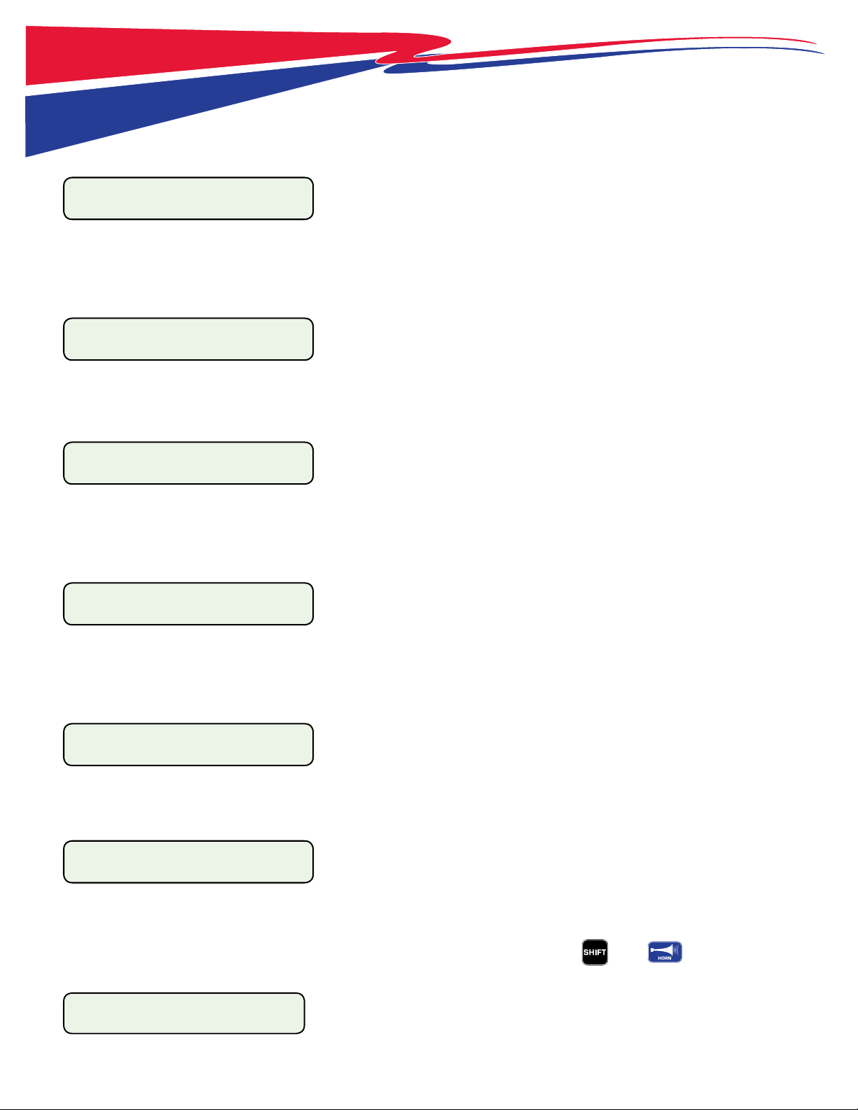
The 8000 Console Keypad when used for an Everbrite Message Center.
Message Center Keypad
Our console is designed to run any 8000 Series
Scoreboard or Everbrite Message Center. Below the
slipsheet window is a fully functioning keyboard style
keypad, perfect for running a message center or for
entering electronic team names (select models only).
To activate the special characters, press and release shift
then press the character.
The red keys send a message or program to the sign or
blanks the display at any time.
Blue keys represents text transition modes.
Press SHIFT + MESSAGE DISPLAY to test all the LEDs.
Number Keypad.
Used in pregame and
gametime operations. Use
the keypad to quickly select
a message to send to the
EMC.
Use the “clear” key to exit
out of a function.
Use the “enter” key to
finalize a command.
When in “EDIT MODE” press
SHIFT+ CLEAR to clear all
messages.
Setup.
Toggles between EDIT and PLAY
MODE. Password is required for
Edit Mode.
Select and Arrow Keys.
Use the arrow keys to select different
messages or programs displayed in
the LCD. Press YES/NO to toggle
answer between Yes and No.
Horn (Amplified Brightness).
Because this console is made for
many uses, and since there are no
horns with message centers, the
HORN key amplifies the brightness of
the EMC LEDs.
Auto/Manual Brightness
Press SHIFT + HORN to enable the
autodimming feature. An Optical
Sensor will determine the proper
brightness of the message center.
Press again for manual controls.
On/Off.
Press once to turn on.
Press and hold to turn off.
5

Definitions
2.1
LED
Light-Emitting Diode (LED) is a semiconductor light source which uses electroluminescence to produce color light. LEDs can last
up to 100,000+ hours and use less energy than traditional incandescent light sources.
Pixel
A pixel is the smallest amount of LEDs that can be turned on at any given time. The standard EMC panel contains 4 LEDs per pixel.
Panel
A panel is a square board that contains an 8x8 matrix of LED pixels.
EMC
Everbrite Message Center (EMC) is a text based message center available in red or amber LEDs.
Characters
Characters make up a line. The EMC is capable of displaying standard text and special characters (!&%<,. etc). Depending on the
height of the sign and the number of lines installed, characters can be displayed as a height of 1 line, 2 lines or 3 lines.
Line
A line is simply a line of text. EMCs are named for the maximum number of lines that can be displayed in a single message frame.
For example, a 1 line emc can display a maximum of 1 line. Each line is approximately 9” tall. The maximum height of any EMC is 27”
(27” for 3 line character size, each 9” high. The cabinet will be larger than the text area).
Transition
Transition refers to how the line enters the sign.
Message
A message (or frame) is the text that is displayed on the emc at any given time. Depending on the size of EMC, the message may
consist of up to 3 lines of text. Messages can be sent directly to the sign or used inside a program. The console can store up to 99
messages.
Delay
Delay refers to the duration that the message will be displayed when used in a program. If only sending a message (not a
program), delay will not be accounted for and the message will remain displayed until a new message or program is sent.
Program
A program consists of up to 20 messages and will run in a loop until another program or message is sent. The sign can store one
program at a time. The console can store up to 99 dierent programs.
6

The radio channels and IDs of the EMC (set at factory, but can be edited).
When the scoreboard and EMC is initially turned on, All LEDs on the scoreboard will run through a series of brightness levels and self
tests. The EMC will display the last program sent to the sign. This program will run in a loop until another program or message is sent.
Brightness of the sign may be set to max for the rst minute of operation before displaying brightness desired.
NOTE: Pressing clear at any time in edit mode will cancel the operation and return to the main edit window (step 5).
1. Turn on Console. Press and hold until LCD and LEDs light.
2. Press 3 to select Message. Use the arrow keys to view more options.
SCOREBOARD CONTROL
MP8000 V.5.** 2010
1. SCOREBOARD
2. STAT PANEL ->
3. MESSAGE CENTER <-
4. TEAM NAMES
NOTE: “LOADING PROGRAM” may appear on LCD after choosing Message Center. This happens when switching between sports and message mode.
3. Press 2 for Edit Mode.
1. Play Mode
2. Edit Mode
4. Enter Passcode, then enter. ( , is default)
Enter Passcode
12345
Because the console will likely be operated by students, a passcode is required to edit any message in the console. The passcode
can be changed by pressing both arrow keys ( ) while in the main menu, entering current passcode and then
selecting “Change Passcode.” Passcode must contain only numbers. If a passcode has been changed and forgotten, call the
All American Scoreboards technical support team or your sales representative. Once messages are entered, any message can be
displayed by either Quick Message or in a Program. This passcode helps prevent unwanted or obscene messages from appearing
on the message center.
5. Press 3 to select Sign Setup
1. Edit Messages
2. Edit Programs
3. Sign Setup
4. Exit Edit Mode
If the consoles and message centers were purchased at the same time, setup will be completed at the factory, although the name,
time and date and other options can be changed. It is recommended that you only change the name and time or date of the
signs. Changing the radio and size options in setup will cause the emc to not respond or display incorrectly.
6. Select the sign to edit.
01 SIGN 1 < SGN
02 SIGN 2
0 2 S I GN 2 < S GN
03 *BLANK*
The arrow on the top left line identies the sign to be selected. If you have more than 1 sign, use the arrow keys( ). Press
enter to select the EMC that the top line in pointing to.
Arrow down to *BLANK* if you want to add a new sign to your console (not typical).
7. Change Sign Description
SIGN 1_
Sign Description
North Gym
Sign Description
The sign description may contain up to 9 characters, and is used as a simple reference for the user of the scoreboard. We suggest
using either the name of the scoreboard that it is by, or geographical references such as North or South. Use the keypad, followed
by enter button to change the name. To leave unchanged, just press enter. Changing the name will not damage the EMC
communication.
SETUP
2.2
7
8. Number of Lines - Height of Sign (DO NOT CHANGE UNLESS INSTRUCTED)
# of Lines (1-3):1
The EMC can either be a 1 line, 2 line or 3 line sign and refers to the actual physical size of the sign. A 1 line sign cannot display 3
lines of text, it can only display a maximum of 1. Changing this from a 1 to a 3 will cause the sign to display incorrectly and will
also add unnecessary prompts to the program.
9. Number of Panels - Width of Sign (DO NOT CHANGE UNLESS INSTRUCTED)
# Panels (5-14)= 11
The number of panels refers to the physical width of the sign. Changing this will cause the message to be o center and possibly
running o the edge of the sign. An 8214emc and an 8209emc (for example) will have a maximum of 11 panels.
10. Sign Channel (DO NOT CHANGE UNLESS INSTRUCTED)
Sign CHAN#=01
This is the radio channel that the console will use to send out the information. If this is changed or incorrect, the message
will not get to the message center. The radio (located in the message center or behind the guest scores in an all-in-one
scoreboard emc) will have this information printed on a label.
11. Sign ID (DO NOT CHANGE UNLESS INSTRUCTED)
Sign ID#=01
This is the identication number that must be correct in order for the message center to listen to the message. If this is
changed or incorrect, the message will not get to the message center. The radio (located in the message center or
behind the guest scores in an all-in-one scoreboard emc) will have this information printed on a label.
12. Set Default Sign
Set Default Sign?YES
Answering YES to this question will make this sign be the sign that will determine how many lines and characters that your
message center can display. This will greatly improve the editing process.
13. Auto LED Brightness
Use Auto Bright?_No
The EMC is equipped with a light sensor that can adjust the brightness level of the LEDs. Auto Brightness will determine
how bright the LEDs need to be to account for the value of ambient light. This will be helpful if the message center is left on
continuously and will prevent the sign from using the maximum setting during nighttime or when less lights are used in an
indoor facility. This can be changed to Manual Brightness while in Play Mode by pressing then .
14. Setting LED Brightness (if Auto Brightness answered YES)
MAX BRIGHT (1-8):_
Blank for no change
The brightness can be set to limit the sign brightness. Enter a value of 1-8. 1 is the dimmest ; 8 is the brightest.
8
SETUP
2.2

9
SETUP
2.3
15. LED Brightness (Auto Bonus Answered NO)
BRIGHTNESS (1-8):
Blank for no change
Enter a manual value for the brightness of the sign. This level can be changed at any time by pressing to amplify the brightness and
change the value. To enable autodimming at any time, press then .
16. Set Date and Time
SET DATE/TIME?_YES
When time needs to be adjusted (corrections or daylight savings time), it must be done to each sign. Answer yes to change. Answer No to
leave the time and date alone. When changing the time, the date must be entered as well. Enter the correct information and press enter
to get to the next screen. See the following for details:
TIME: 12:00A
(HH:mm)(Am/Pm) Enter a 4 digit time (04:05 = 4:05) and an A or a P, press enter.
DATE: 03/18/10
(MM/dd/YY) Enter a 2-digit month, 2-digit date and 2-digit year, press enter.
MON <DAY
TUES Use the arrow keys ( ) to select a day (top line is select), press enter.
NOTE: Everbrite Message Center MUST be
in direct line of site from a radio console in
order to receive radio signal.

The message center will be supplied with canned messages to help get things going. These messages can
be edited or deleted. Any message can be accessed for a quick message or placed into a program (a series of messages).
NOTE: Pressing clear at any time in edit mode will cancel the operation and return to the main edit window (step 5).
1. Turn on Console. Press and hold until LCD and LEDs light.
2. Press 3 to select Message. Use the arrow keys to view more options.
SCOREBOARD CONTROL
MP8000 V.5.** 2010
1. SCOREBOARD
2. STAT PANEL ->
3. MESSAGE CENTER <-
4. TEAM NAMES
3. Press 2 for Edit Mode.
1. Play Mode
2. Edit Mode
4. Enter Passcode, then enter. ( , is default)
Enter Passcode
12345
Passcode may be edited and can be dierent than displayed above. See “Setup” section for more details.
5. Press 1 to select Edit Messages
1. Edit Messages
2. Edit Programs
6. Select message to edit or select new message
01 DEFENSE! <MSG
02 3 POINTER!
09 *BLANK* <MSG
The “<MSG” characters on the right side of the LCD indicate the message to be edited (top line of LCD). Use the arrow keys (
) to navigate to a dierent message and press or . Messages will be displayed by the rst 9 characters of the
message.
Navigate to the last message to add another message (empty message will be labeled as Blank). Follow the same instructions
below to add or edit a message.
7. Message Delay
00:01 < MSG DELAY
00:02
The delay is how long a message will be displayed when used in a program. Delay does not pertain to quick messages. Use the
arrow keys ( ) to navigate to a dierent time (from 1 second to ve minutes), press or .
8. Line Height (will only display for a default sign of 2 or 3 lines)
LINE HEIGHT(1-3):
For most combo signs (scoreboard and EMC in same cabinet) this screen will always equal 1 or not be displayed at all. For signs
with 2 or 3 lines (message area of approximately 20” to 30” high) this relates to the height of the character, spanning 2 or 3 tiles
high. For example, if a 3 line sign is used, 3 single lines may be displayed, a combination of 2 line height and 1 line height may be
displayed, or a single 3 line height may be displayed.
10
3.0
EDIT MESSAGES

9. Enter or Edit the Message
DEFENSE!
Message Text
Using the keypad, enter the message. To use punctuation or special characters, press the SHIFT key (lower left) before pressing the
special characters. To clear a line, press CLEAR LINE (upper center). Use the ARROW KEYS to move the cursor. Use BACKSPACE to
delete the character before the cursor. If more characters are entered that can t on the sign, the Transition will be automatically
changed to TRAVEL. To change the mode, the message must be shortened.
9. Enter the Line Transition
LINE TRANSITION: PD
LINE 1 ‘Blue Keys’
NOTE : If more characters are entered that can t on the sign, the
Transition will be automatically changed to TRAVEL (AT = AUTO
TRAVEL). To change the mode, the message must be shortened.
HOLD
FLASH FLASH
PUSH UP PUSH UP
PUSH DOWN
PUSH DOWN
WIPE UP WIPE UP
WIPE LEFT WIPE LEFT
WIPE RIGHT WIPE RIGHT
TRAVELTRAVEL
WIPE DOWN WIPE DOWN
WIPE IN WIPE IN
WIPE OUT WIPE OUT
Transitions Dened:
Below is a description of the line transitions. Each line in a message can enter the frame
in a unique way (for example, line 1 can ash as line 2 wipes). On the left is a graphical
illustration of the transitions. The two letter abbreviation is what will be displayed on
the LCD screen once a mode is selected. With the exception of Travel, the amount of
characters that can be entered in your text depends on the width of the sign and the
height of the characters.
TRAVEL (TR) - Message travels from right to left (50 Characters Max)*.
HOLD (HD) - Message appears and stays on line.
FLASH (FL #) - Message will ash on and o. Once ash is selected, console will ask for a
number. This number refers to the amount of times that the message will ash.
PUSH UP (PU) - Message rises from the bottom of the line and stops when centered.
PUSH DOWN (PD) - Message enters from top and stops when centered.
WIPE UP (WU) - Message appears in the center and erases from the bottom.
WIPE DOWN (WD) - Message appears in the center and erases from the top.
WIPE LEFT (WL) - Message appears in the center and erases from the right.
WIPE RIGHT (WR) - Message appears in the center and erases from the left.
WIPE IN (WI) - Message appears in the center and erases from both ends.
WIPE OUT (WO) - Message appears in the center and erases from inside to outside.
*NOTE: Each message can contain a maximum of 67 characters.
3.0
EDIT MESSAGES
11

10. Enter the Message Transition Speed
MSG Speed (1-3):
ALL LINES
Message Speed refers to the speed of the transition of the message. A speed of 1 will enter the display at the slowest speed. A speed of 2
will enter the display at a medium speed. A speed of 3 will enter the display at the fastest speed. This number will aect all line speeds
in a single frame.
11. Add Another Line (if available)
Repeat Steps 7-9 for Remaining Lines
If sign is a single line, skip to step 12.
If sign is a 2 line sign and the rst line’s line height was 2 lines high, skip to step 12.
If sign is a 3 line sign and the rst line’s line height was 3 lines high, skip to step 12.
If lines are remaining on the message frame, answer YES to the prompt shown below and repeat steps 7-9. When all lines are completed,
proceed to step 12.
Another Line? _Yes
12. Enter the Line Transition
A T T AC H S C H ED UL E ? _ NO
Attaching a schedule will result in the message to only appear in a program on a given day. For example, if an EMC was being used as a
lunch schedule, a line that shows “TACOS” could be programmed to be displayed every Tuesday. Schedules make it possible to send a
program that automatically displays certain messages on certain days. Schedules do not aect quick messages.
If answer yes:
START TIME: 12:00A
(HH:mm)(Am/Pm)
Enter the time (2 digit hour, 2 digit minute, A or P) that the message will start.
STOP TIME: 12:00A
(HH:mm)(Am/Pm)
Enter the time (2 digit hour, 2 digit minute, A or P) that the message will stop.
MON <DAY
TUES
Enter the day or days that the message will appear.
13. Test the Message
Toggle between Play Mode and Edit Mode by pressing .
Toggle between Quick Message and Program by pressing .
Select the message (or program) by using the arrow keys ( ), then press .
3.0
EDIT MESSAGES
12

4.0
EDIT PROGRAMS
1. Turn on Console. Press and hold until LCD and LEDs light.
2. Press 3 to select Message. Use the arrow keys to view more options.
SCOREBOARD CONTROL
MP8000 V.5.** 2010
1. SCOREBOARD
2. STAT PANEL ->
3. MESSAGE CENTER <-
4. TEAM NAMES
3. Press 2 for Edit Mode.
1. Play Mode
2. Edit Mode
Once in Edit Mode, toggle between Play Mode and Edit Mode by pressing .
4. Enter Passcode, then enter. ( , is default)
Enter Passcode
12345
Passcode may be edited and can be dierent than displayed above. See “Setup” section for more details.
5. Press 2 to select Edit Programs.
1. Edit Messages
2. Edit Programs
6. Select Program to Edit or Create
1. Test <PGM
2. *BLANK*
The “<PGM” characters on the right side of the LCD indicate the program to be edited (top line of LCD). Use the arrow keys (
) to navigate to a dierent program and press or . A program cannot be deleted, but all information can be edited.
7. Enter Program Description
Pgm Description
TEST
Pgm Description
MY PRGM
Enter a program description. The name can be a maximum of 9 characters. Use then to clear the line or to
delete the character before the cursor. Use the arrow keys ( ) to insert text between characters.
8. Select Messages to Display
Use SELECT btn to
add messages
02 3 POINTER! *1*<
03 AIR BALL *7*
Press Select to bypass the rst screen. Use the arrow keys ( ) to navigate through dierent messages and press in
the order that the messages will be displayed. The order will be displayed by *order number*. Select up to 20 messages for each
program. When nished with selections, press .
Deselect a message (pressing to a selected message) will move up all messages that follow.
To move a message up or down in a program list, press or .
Pressing when a message is highlighted will send the message to the sign as a preview.
To view the program, enter Play Mode ( ), press to toggle between Programs and Quick Messages, select the
program using the arrow keys ( ), then press . 13

PLAY MODE
14
5.0
Play mode is designed to only send messages and programs that were previously loaded in edit
mode. This was done to prevent unwanted messages from appearing on the message center. Once messages have been entered
by an approved person, the message center can be handed o to the operator (student, etc).
1. Turn on Console. Press and hold until LCD and LEDs light.
2. Press 3 to select Message. Use the arrow keys to view more options.
SCOREBOARD CONTROL
MP8000 V.5.** 2010
1. SCOREBOARD
2. STAT PANEL ->
3. MESSAGE CENTER <-
4. TEAM NAMES
3. Press 1 for Play Mode.
1. Play Mode
2. Edit Mode
4. Select Sign(s) to Send Messages
* 01 NORTH GYM <SGN
02 SOUTH GYM
The “<SGN” characters on the right side of the LCD indicate the sign to be sent to. Use the arrow keys ( ) to navigate to the
signs (signs may be entered or edited in Edit Mode) and press . A “ *” will be displayed before each sign, indicating that this
sign is selected. When nished selecting signs, press .
NOTE: When multiple signs are selected, the messages will be sent to one sign, and then resent to another sign. There will be a
slight delay between message centers that will equal the time that is necessary to switch radio channels and send.
5. Toggle between Quick Messages and Programs
SHOW MESSAGE to go
between Msg and Pgm
Press to bypass this screen and to toggle between Quick Messages and Programs.
6. Select a Quick Message or Program
<-QUICK MESSAGE ->
Msg01 DEFENSE!
<-PROGRAMS ->
Pgm01 MY PRGM
Press to toggle between Quick Messages and Programs.
Use the arrow keys ( ) to navigate to the message or program to send.
A number entered via the number pad followed by to quickly get to a specic message.
7. Send to Sign
<-QUICK MESSAGE ->
Msg01 DEFENSE!
<-PROGRAMS ->
Pgm01 MY PRGM
Use the arrow keys ( ) to navigate to the message or program to send, then press .
8. Toggle to Edit Mode
Enter Passcode
See the edit sections for more details.

15
6.0
QUICK REFERENCE
Getting into message mode:
(press and hold... wait for menu items) then then
NOTE: “LOADING PROGRAM” may appear on LCD. This happens when switching between sports and message mode.
Play mode
When initially going into play mode, selects sign(s) to send messages - press to conrm
Sends message or program to sign
Quick message will remain until new message or program is sent
Program will run in a continuous loop until new message or program is sent
Toggles between messages and programs
Scrolls left (up numerically) through messages and/or programs before sending to sign
Scrolls right (down numerically) through messages and/or programs before sending to sign
(or any message number) then Jumps to message number for quick display.
Change the brightness of the EMC. Enter values from (dimmest) to (brightest), press
then Toggle between auto brightness and manual brightness
Blanks display until another message or program is sent or until is pressed
then Runs through a display test. All LEDs light, then a single row goes through brightnesses
Resumes a program after display blanks ( ) or after a quick message is sent
Tip: To get a program to sync closer between multiple signs, press then .
Toggles between Edit and Play mode
Edit mode (many keys in play mode operate the same in message mode)
When attempting to send a message to a sign(s), use to select EMC(s) - press to conrm
Also selects programs or messages to add (*BLANK*) or edit
May also be used as an in many functions
Sends message to sign for preview when editing messages or programs. This key will not send a program while in edit mode.
Press this to inset time, temperature or date in the LINE TEXT screen when editing a message
Press again to toggle between options. Auto Travel will occur if text is too long
NOTE: Text line must only have time and temp functions (no other text or characters)
All of these blue keys are transition mode eects. See page 11 for more details.
NOTE: Message will Auto-Travel if text is too long to t on sign.
then Will clear all messages. The console will conrm before clearing. All programs will also be cleared.
16
7.0 8000 Series Updater
Periodically, an update to the console rmware is released from All American Scoreboards. These releases
may contain improvements to the existing sport operations, changes in the menu, additional sport pro-
grams or other improvements. If satised with the operation of your scoreboard, an update may not be
necessary. Each rmware release will be explained at AllAmericanScoreboards.com.
A console rmware may be updated ONLY if the following conditions apply:
1. The console has rmware version 4.00 or greater.
2. A PC is available with a USB port and an internet connection.Requires Windows XP Home
Edition, Windows XP Professional, Windows Server 2003, or Windows Vista with the latest
service pack updates.
3. A “USB A” (male) to “USB B” (male) cord is available.Cord is available from many electronics
retailers or directly from All American Scoreboards.
Instructions for Updating the Console Firmware.
STEP 1: Download the most recent program from AllAmericanScoreboards.com and follow installation
instructions. Launch program - located in Program Files\All American Scoreboard\Update The rmware
update program is available by contacting tech support and supplying an email address.
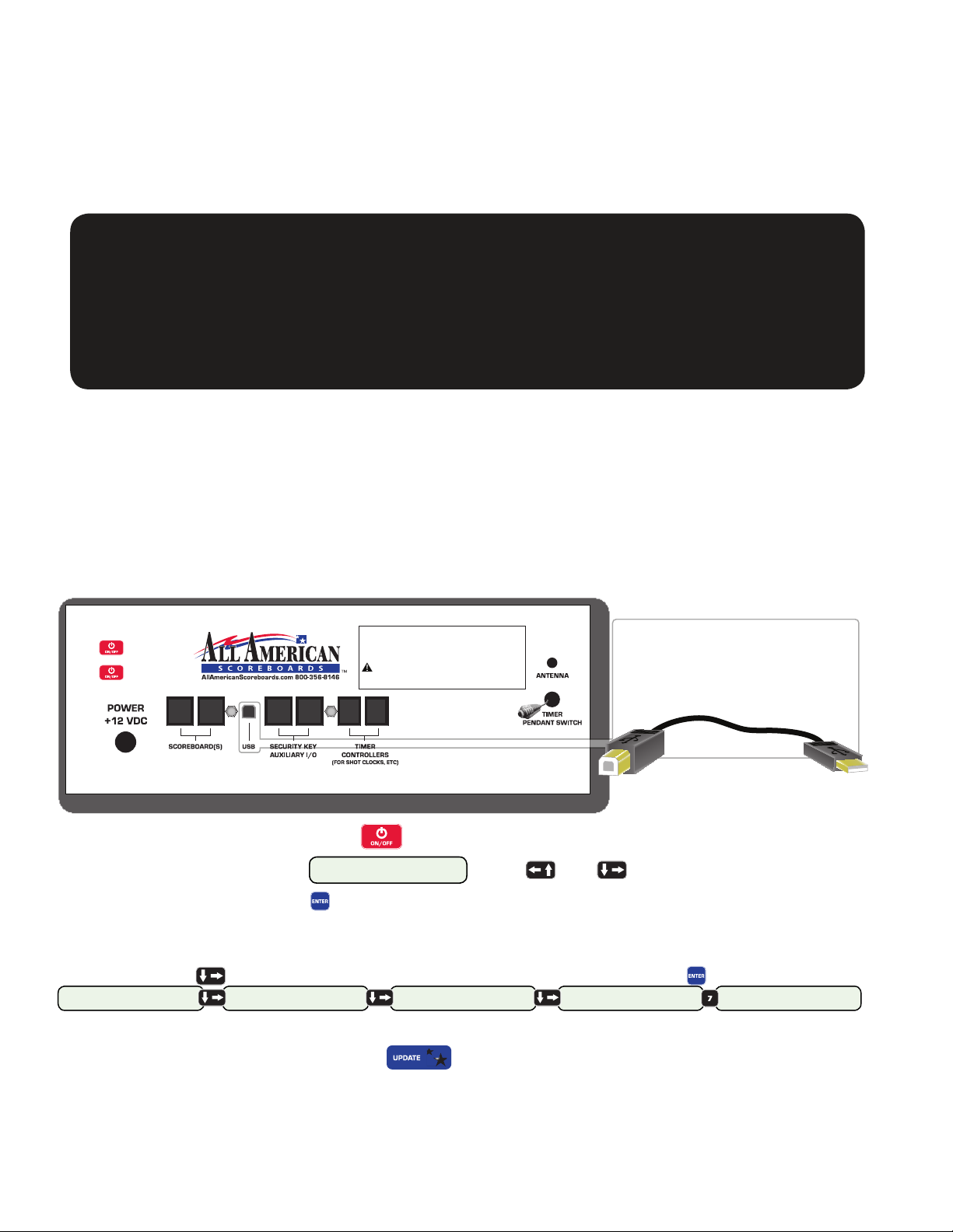
Step 2: On the back of the 8000 Series Console, plug in the USB B into the USB connection.
Step 3: Plug in the USB A into the computer. All American Scoreboards recommends using a USB 2.0
port from the PC. Using a standard USB port will work, however the time to update will be more than
doubled.
STORING:
Battery should be fully charged when storing, and should be kept at room temperature.
Recharging once every 30 to 45 days of storage is recommended. If batteries are stored
longer, it may take two or three cycles before full run time is restored.
WARNING! This equipment has been approved for mobile applications where
equipment should be used at distances greater than 20cm from the human body
(with the exception of hands, wrists, feet and ankles). Operation at distances less
than 20cm is strictly prohibited. Excessive RF exposure should be avoided.
Press once to turn on.
Follow prompts on screen.
Press and hold to turn off.
TRANSMITTER MODULE FCC ID:KQL-PKLR2400-200 IC:22683911808A3 17
WARNING! This device complies with Part 15 of the FCC Rules. Operation is
subject to the following two conditions: (1) This device may not cause harmful
interference, and (2) This device must accept any interference received, including
interference that may cause undesired operation.
RJ45 RJ45 RJ45 RJ45 RJ11 RJ11
USB Interface Cable
Plug the “USB B” into the back
of the console. Plug the “USB A”
into any USB port on your PC.
USB B (male)
to console.
USB A (male)
to computer.
Step 4: Turn on console by pressing .
Step 5: When screen displays 1. SCOREBOARD
2. STAT PANEL -> , press and simultaneously.
Step 6: Enter passcode, press .When the console is sent out from All American Scoreboards, the
Passcode is 12345. If passcode has been changed, enter new passcode. If passcode is lost or forgotten,
contact All American Scoreboards.
Step 7: Arrow ( )over to “PC CONNECTION”. Press the appropriate number ( ).
1. SCOREBOARD
2. STAT PANEL ->
3. MESSAGE CENTER
4. TEAM NAMES ->
5.CHANGE PASSWORD
6.BOARD IDS ->
7. PC CONNECTION
8. BOARD TYPE ->
WAITING TO CONNECT..
Console will display “ WAITING TO CONNECT..”
Step 8: In the computer program, press .The program will run for 2 to 5 minutes (may be lon-
ger depending on computer speed and data connection). The console will erase the necessary existing
information and load the new information. If an update fails (power outage, cord is pulled, etc), try again
by powering o and on and restarting computer program. Do not disconnect until updater says “OK to
Unplug USB”. Console will automatically restart.
(continued on next page...)

17
8000 Series Updater ...continued
Update Button.
When pressed, button will be
grayed out.
Information Status Area.
Shows what is happening.
Turns red if errors occur.
Status Bar.
UPDATER WINDOW
The Updater Program will report the number of errors that occurred during the update. If the error
count is anything but zero, the bootloader MUST be run again. If error count is 0 and console fails to
restart (or console displays WAITING TO CONNECT.. ), turn o console ( ) and then turn on by pressing
and at the same time until console turns on.
NOTE:
After the update is complete, the sports program may be forced to load upon startup by press-
ing & at the same time.
After the update is complete, the message program may be forced to load upon startup by
pressing & at the same time.
Why update your All American Scoreboards console?
In most cases, your console is doing everything that you want it to do. If you are comfortable with how
everything is operating, then you probably don’t need to update your console. Here is a sample of some
of the improvements that have taken place in the past:
- Improved stat panel control.
- Shot clock light strips and end of game light strips control.
- Ability to nd “sweet spot” for radio control (requires V2 Radio).
- Improved functionality in various sports - for example; in baseball added option for “Auto Hit Indicator.”
- Ability to control horn length for both end of period and shotclocks.
- Ability to back up console settings and segments.
- Improved Team Names functionality.
- Ability to control Everbrite Message Center and load and backup messages and programs.
(continued on next page...)
FIRMWARE UPDATE
7.0

18
Why update your All American Scoreboards console? (...continued)
Updating your console will likely provide better functionality for your console and scoreboard. If your
console rmware is 5.05 or lower (see below), then all segment programs and sport settings that have
been saved (scoreboard brightness, fouls, period length, etc) will be overwritten with the defaults set in
the upgrade package. Version 5.06 and above allows the sport settings, segments and messages to be
backed up and loaded into any console.
Updating your console rmware will bring your console to the same version that is being shipped out
with a new scoreboard. All consoles with a rmware version of 4.0 or above are compatible with
console upgrades, however, it is not recommended to load a previous version (downgrade) unless
instructed to do so by tech support. For example, a radio component was changed at version 5.0. A
console may be upgraded from a version 4.XX to a version 5.XX, but a version 5.XX with the new V2 Radio
cannot be downgraded from a version 5.XX to 4.XX.
If your console is v3.24 or lower, a new backplate must be installed in your console to have the
ability to upgrade. It is recommended that you understand what improvements have been made before
deciding to replace the internal components of your console.
CHANGING THE HORN LENGTH (VERSION 5.01+)
Download and install Console Version 5.01 or greater. Call All American Scoreboards for details. Installing
a newer version of All American Software will automatically remove previously installed versions from
your computer.
Repeat Steps 1-7 on previous page. Console will read WAITING TO CONNECT.. .
8. Click on Start Icon on your computer. Hover over “ALL PROGRAMS” and then over “ALL AMERICAN
SCOREBOARDS.” Select “CONSOLE SETUP OPTIONS.”
9. Click on GET SETTINGS. Loaded values from console will display on computer window. Horn lengths
are displayed as tenths of a second - the lowest value is 1 (1/10 of a second) and the highest value is 99
(9.9 seconds). The default horn lengths are set to 15 (1.5 seconds). Change the values and click on PRO-
GRAM.
BACKING UP CONSOLE TO A COMPUTER (VERSION 5.06+)
Download and install Console Version 5.06 or greater. Installing a newer version of All American Software
will automatically remove previously installed versions from your computer.
Repeat Steps 1-7 on previous page. Console will read WAITING TO CONNECT.. .
8. Click on Start Icon on your computer. Hover over “ALL PROGRAMS” and then over “ALL AMERICAN
SCOREBOARDS.” Select “CONSOLE SETUP OPTIONS.”
9. Click on BACKUP CONSOLE. The computer will store EMC Sign Information, EMC Messages, EMC Pro-
grams, Segment Timing and Sport Setup Information. This le can be loaded back into any console with
version 5.06+. by clicking on “Restore Console.” The le can be named and saved using traditional operat-
ing system rules.
FIRMWARE UPDATE
7.0

WARNING! OPERATION OF THE UNIT WITH THE ELECTRICAL EXPOSED IS
DANGEROUS. BE SURE ALL TOOLS AND ANY OTHER MATERIALS ARE REMOVED
FROM THE UNIT, AND ALL ACCESS COVERS ARE REPLACED AND CLOSED BEFORE
POWER IS TURNED ON.
NOTE: For Advanced Trouble Shooting, Service Manuals and Replacement Part Information
go to www.allamericanscoreboards.
8.0 Safety Information
The owner of the All American Scoreboard (AAS) is responsible for safe operation and repair.
He therefore is obliged to familiarize operating personnel with the contents of this manual
and make them aware of all possible hazards.
NOTE: When using this equipment, always follow the manufacturer’s instructions for
safe operation. In case of emergency, please telephone Technical Support or a qualied
service technician.
Do not operate the sign until it is completely assembled and installed per the instructions
supplied by AAS.
AAS recommends that your main power be installed by a licensed electrician in accordance
with the local building and electrical codes.
All equipment must be grounded in accordance with the local building and electrical codes.
AAS recommends Earth Link Ground.
If any part of the Scoreboard equipment is malfunctioning or has been damaged, cease
operation and consult with AAS Technical Support or qualied service technician before
further use.
Use only AAS specied or recommended replacements parts.
WARNING! USE A LOCK OUT/TAG OUT ON CIRCUIT BREAKERS OR “POWER
ON/OFF” SWITCHES WHEN PERFORMING INSTALLATION, REPAIRS OR
MAINTENANCE.
When performing repairs be mindful of the weather and work area conditions. Avoid the
unit’s exposure to the elements, water and debris, or anything that may be dangerous or
cause damage to the equipment.
WARNING! OPERATION OF THE UNIT WITH THE ELECTRICAL CIRCUITRY
EXPOSED IS DANGEROUS. BE SURE ALL TOOLS AND ANY OTHER MATERIALS
ARE REMOVED FROM THE UNIT, AND ALL ACCESS COVERS ARE REPLACED
AND CLOSED BEFORE POWER IS TURNED ON.
CAUTION: Use of solvent cleaners or a power washer on your Scoreboard may
cause permanent damage.
8.0
Safety

Warranty
9.0 Warranty
Five Year Limited Warranty
Non-compliance with procedures of Installation, Safety, Operation and/or Maintenance
practices dened in this manual may result in a Warranty issue.
This warranty extends to and is enforceable by only the original consumer purchaser
and only for the period (during the applicable term) which the product remains in the
possession of the original consumer purchaser. “Original consumer purchaser” means the
person who rst purchased the product covered by this warranty other than for purpose
of resale. This warranty does not apply if it is found that at any time the equipment has
not been used for its intended purpose.
NOTE: Please ask your dealer, distributor or sales representative for details.
CAUTION! Any unauthorized changes or modications to this unit without
our prior written approval will void the user’s warranty and will transfer health
and safety obligations to the user
CAUTION! Changes or modications to this unit not expressly approved by
the party responsible for compliance could void the user’s authority to operate
the equipment
NOTE: This equipment has been tested and found to comply with the limits for a
class “A” Digital device, pursuant to part 15 of the FCC rules. These limits are designed
to provide reasonable protection against harmful interference when the equipment
is operated in a commercial environment. This equipment generates uses and can
radiate radio frequency energy and, if not installed and used in accordance with
Owner’s Manual, may cause harmful interference to radio communications. Operation
of this equipment in a residential area can cause harmful interference in which case
the user will be required to correct the interference at their expense.
9.0
19
Table of contents
Other All American Scoreboards Music Mixer manuals


