Allanson 2275 User manual

ELECTRONIC IGNITOR
INSTRUCTION MANUAL - TYPE 2275
CANADA: 83 Commerce Valley Drive East, Markham, Ontario L3T 7T3 | T: 1.800.661.7251 | Fax: 416.752.6717
USA: 99 Adams Blvd., Farmingdale, New York 11735 | T: 1.631.293.3880 | Fax: 1.631.293.3470
This instruction manual provides you with application information on the OMNI™ Electronic Ignitor. Allanson’s
electronic ignitors are designed for intermittent duty (constant) and/or interrupted duty - providing the most reliable
ignition source for gas and oil.
Abosolute Minimum Readings: Mechanical Specications:
Input Supply Voltage (V):
Input Supply Frequency (Hz):
Primary Volt - Amperes (VA)
Secondary Voltage (kV peak):
Secondary Frequency (kHz):
Secondary Short Circuit Current (mA):
Storage Temperature:
Operating Temperature:
Operating Relative Humidity (%):
Loading Air Gap (inches):
108-132
50/60
87
17.5
>20
28
-40 to +80
-30 to +40
90
1/16 to 3/16

1. Before installation, inspect the case and the porcelain bushings for possible damage during transportation and handling. Do not use the
product if the secondary bushings are chipped and/or cracked.
2. Choose the correct base plate from the kit (if provided) to t the burner. Route the primary lead wires to the appropriate lead exit on the base
plate and fasten the electronic ignitor to this plate with the three self-tapping screws provided.
3. Install the electronic ignitor assembly on the burner and route the primary leads to the junction box for connection. Connect the black lead
to the negative terminal (-) and the red lead to the positive terminal (+) of the supplies. (Reversing the lead connection will result in the
unit not operating properly). Use only UL Listed and CSA approved wire nuts.
Chek-Mate™(Allanson’s Ignitor/Transformer tester). Use it to touch any brand of ignitor/transformer. Simply touch the high voltage spheres to
the high voltage contacts. If the green LED lights up, the unit is performing well.
Short Circuit Current Test. Connect a true RMS high frequency milliammeter to the output terminals. Energize the primary with 120 Volts at
50/60 Hz. The reading on the milliammeter should be within 10% of the rated.
Open Circuit Test. For this test you need an oscilloscope and a high voltage oscilloscope probe. Connect the high voltage probe from one
secondary to the ground terminal (screw in front and between the high voltage bushings). Measure the peak of the wave form on the oscilloscope.
Repeat the procedure for the opposite high voltage terminal. The sum of the two readings should be within 10% of the name plate rating.
Field Testing. Connect the electronic ignitor grounding terminal to a good ground. Connect the primary leads of the electronic ignitor to 120 Volts.
Energize the primary. Holding the handle of a well insulated screw driver, touch one part of the shaft of the screw driver to one high voltage
terminal. Pivot on this terminal until you draw an arc from the opposite terminal. Gradually increase the air gap and notice the distance at which the
arc is extinguished. The minimum distance should be 1/2”.
The OMNI®Electronic Ignitor has no moving parts. The only maintenance required is the cleaning of the porcelain bushings with a soft cloth during
the annual furnace inspection.
The OMNI®2275 Electronic Ignitor can be tested as follows to ensure that it is operating properly.
WARNING
This procedure is to be carried out by qualied personnel ONLY.
The voltages and currents available can cause serious injury and/or death. Extreme caution is to be used to avoid contact with the
primary live leads. Do not allow any parts of your body to come closer than 5 inches to the energized secondary terminals or parts of the
secondary circuit. Ensure the mid-point of the transformer is grounded before energizing the primary.
Installation:
Maintenance:
Testing:
#21-620
1221
#21-620
1221
Popular Fireplace Accessories manuals by other brands
Hearth & Home
Hearth & Home FOLIO Series installation instructions
ASO Safety Solutions
ASO Safety Solutions Safety-Contact-Mat Information sheet
O-TL
O-TL System 4 LP Installation and operation guide

Muskoka
Muskoka Electric Fireplace Mantel MM281COK Assembly instructions

Sherwood
Sherwood 50-1445 installation instructions
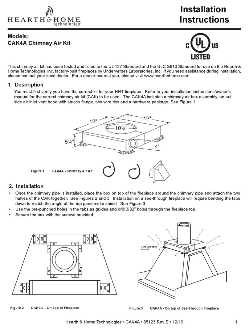
Hearth & Home
Hearth & Home CAK4A installation instructions
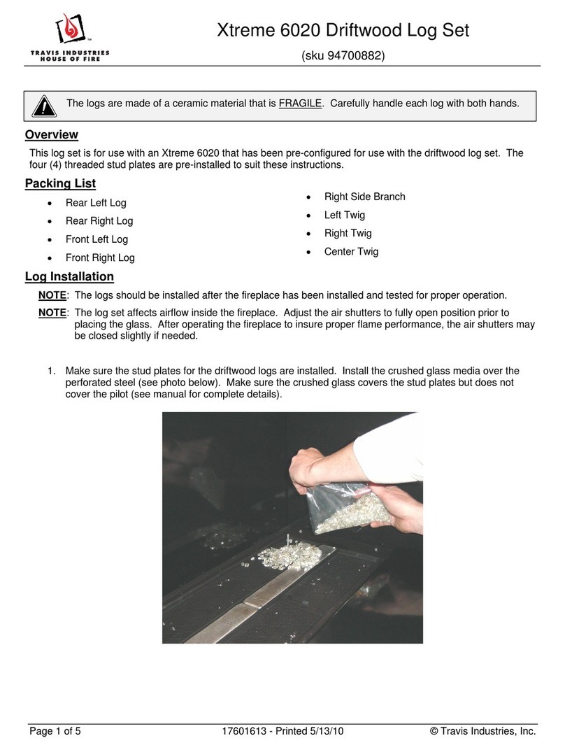
Travis Industries
Travis Industries 94700882 manual

Northline Express
Northline Express Simpson Dura-Vent Type B Gas Vent installation instructions

Heat & Glo
Heat & Glo PORTRIM6-BR quick start guide

RealFlame
RealFlame Chateau 5950 Mantel assembly instructions
Heat & Glo
Heat & Glo SSF-LUX60-BK installation instructions
RealFlame
RealFlame T0026 manual
