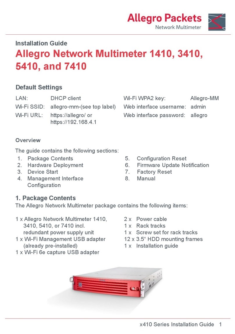
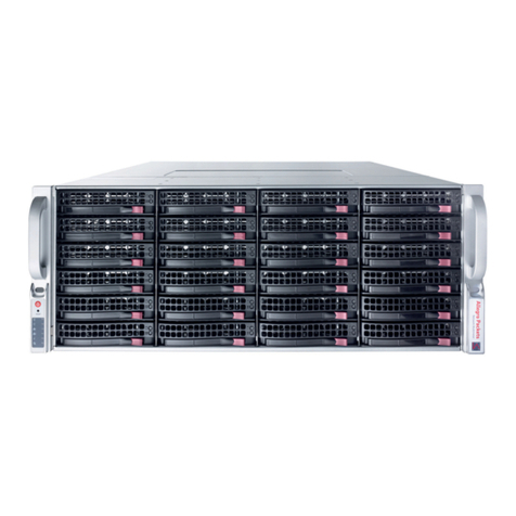
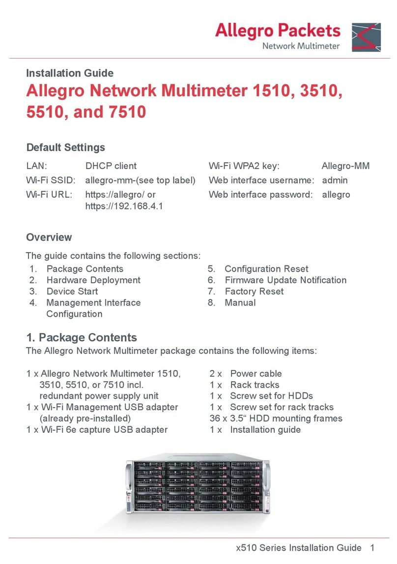
Allegro Packets 1310 User manual

Installation Guide
x310 Series Installation Guide 1
Allegro Network Multimeter 1310, 3310,
5310, and 7310
Default Settings
LAN:
DHCP client
Wi-Fi WPA2 key:
Allegro-MM
Wi-Fi SSID:
allegro-mm-(see top label)
Web interface username:
admin
Wi-Fi URL:
https://allegro/ or
https://192.168.4.1
Web interface password:
allegro
Overview
The guide contains the following sections:
1. Package Contents
2. Hardware Deployment
3. Device Start
4. Management Interface
Configuration
5. Configuration Reset
6. Firmware Update Notification
7. Factory Reset
8. Manual
1. Package Contents
The Allegro Network Multimeter package contains the following items:
1 x Allegro Network Multimeter 1310,
3310, 5310, or 7310 incl.
redundant power supply unit
1 x Wi-Fi Management USB adapter
(already pre-installed)
1 x Wi-Fi 6e capture USB adapter
2 x Power cable
1 x Rack tracks
1 x Screw set for HDDs
1 x Screw set for rack tracks
10 x 2.5” HDD mounting frame
1 x Installation guide

x310 Series Installation Guide 2
2. Hardware Deployment
2.1 Management Access (Control Plane)
Step 1: Connect power supply
Step 2: Connect management LAN
Alternative: Insert Wi-Fi
Management adapter to any of
the USB ports
By default, for LAN, the device will query an IP address via DHCP dynamically
from your network. For Wi-Fi, by default the device will open an Access Point so
smartphones, tablets, or laptops can connect to the Access Point and access the
web interface.
In case Wi-Fi access is not possible and no DHCP server exists, a temporary IP
address can be assigned by using an USB keyboard and pressing ‘Shift+S’. The
LAN interface IP is temporarily set to 192.168.0.1. If this is already taken, another
address in the range from 192.168.0.1 to 192.168.0.10 will be used.
You can check the assigned IP address on a connected monitor.
2.2 Network Measurement Installation (Data Plane)
The Allegro x310 Series, consisting of the Allegro 1310, 3310, 5310, and 7310,
analyzes all data traffic transmitted through all network interfaces of the built-in
measurement cards. The Allegro Network Multimeter is equipped with two SFP+
ports and can be extended by up to 3 network cards with 2 or 4 ports each. The
appliance can be used in Sink or Bridge mode.
2.2.1 Bridge Mode
Each 2 adjacent ports of a network card form a Layer 2 bridge, which forwards all
incoming data traffic to the corresponding interface.
WARNING: Bridge mode is a software-only TAP and will not work in case of a
device error or after power off.
2.2.2 Sink Mode
Received packets will be processed but not forwarded. Connect the Allegro
Network Multimeter to a hardware TAP by connecting both TAP interfaces to the
device. Alternatively, a switch or router mirror port can be connected to any of the
device network interfaces.
Default configuration is bridge mode, thus running as an inline device. The link
mode can be configured via the web interface (menu ‘Settings‘ → ‘Global
settings’).
Power supply
MGMT IP KVM

x310 Series Installation Guide 3
2.2.3 WiFi Capturing
To perform WiFi measurements, the WiFi Capture USB adapter needs to be
connected to any USB 3.0 port on the back of the Allegro Network Multimeter.
Additional adapters can be connected via USB 3.0 hub.
2.3 Installing Your Own HDDs or U.2 NVMe SSDs
The Allegro x310 series can be used with up to 10 2.5“ NVMe or SATA HDDs. These
must be mounted in the tool-less drive carriers.
To install a drive, first pull out the two spring
locking clasps of the carrier. Then tilt the drive
into the carrier, so that the two carrier posts fit
into two drive mounting holes. When the drive
sits fully in the carrier, close the locking clasps
to hold the other two drive mounting holes.
3Device Start
1. Press the power button at the front of the device. The device will boot within five
minutes.
2. Connect to the management interface:
1. LAN access: The device gets its IP from the DHCP server in your network.
Check the console output on an attached monitor or ask the server
administrator for the IP of the device, then enter the IP into the URL bar of your
web browser.
2. Wi-Fi access: The device sets up an access point. See the Default Settings
section for the SSID and WPA2 password to configure your Wi-Fi connection
and the Wi-Fi URL you need to enter in the URL bar of your web browser.
3. Web interface authentication: See section Default Settings for Username and
Password.
4Management Interface Configuration
You can configure the management interfaces by accessing the web interface at
‘Settings‘ → ‘Management interface settings’. The available options are described
in the online manual which can be accessed via the web interface.
post
locking clasps

x310 Series Installation Guide 4
5Configuration Reset
The ‘Configuration reset’ restores the configuration to the default settings:
1. Web interface: Go to menu ‘Settings’ → ’Administration’ and click on ‘Reset
system configuration’. All settings including the network configuration will be
reset to factory default.
2. Boot menu: Follow the instructions in section 7. Factory Reset.
6Firmware Update Notification
Update information via email
With each release, Allegro Packets will send you an email with release notes and a
link to download the update. If you want to be added to this mailing list, please
send an email with your serial number (‘Info’ → ‘System Info‘ → ‘System ID’) to
support@allegro-packets.com and the subject ‘Release’.
Using the Allegro web interface
Start your Allegro Network Multimeter and click ‘Settings’ in the menu and then
‘Firmware updates’. Click on ‘Check for new firmware’ and the Allegro Network
Multimeter will tell you if a new version is available for download. If so, you can
choose to download it directly to the device. In addition, this page provides an
overview of all versions available to you. To install the new version, click on
‘Activate’.
7Factory Reset
The ‘Factory reset’ will clear the entire system installation and restore the firmware
to the version that was originally shipped with the Allegro Network Multimeter.
1. Power off the Allegro 1310, 3310, 5310, or 7310.
2. Remove all network cables from the device.
3. Connect a display to the VGA port.
4. Connect a USB keyboard to any of the four USB ports.
5. Power on the device by pressing the power button.
6. After initialization a boot menu appears. Select ‘Factory reset’ and press Enter.
Or select ‘Configuration reset’ to reset the configuration settings only while
keeping the current firmware installation.
7. The device will boot, reset everything to factory settings, and reboot again.
8. The device is now reset to factory settings.
9. Disconnect the display and keyboard.
8Manual
The device manual can be accessed from the web interface. Each web section
contains a button to access context-specific documentation. The complete manual
can be opened by clicking on the ‘Manual’ link in the menu and then choosing the
Offline manual in the appliance or the Online manual at:
https://allegro-packets.com/wiki
Getting Help: Please send an email to support@allegro-packets.com or call +49 341 59 16 43 54.
Allegro Packets GmbH | Internet allegro-packets.com | Installation Guide – Allegro Network Multimeter x310 © Rev 2023-08 All rights reserved.
This manual suits for next models
3
Other Allegro Packets Network Hardware manuals
Popular Network Hardware manuals by other brands
Paradyne
Paradyne 7510-A2-GB20-00 727 user guide
Enterasys
Enterasys S Series Upgrade Installation Guide
Huawei
Huawei RRU3203 installation guide

MikroTik
MikroTik RBwAPG-60ad-A manual
Cisco
Cisco AIR-WLC2106-K9 - Wireless LAN Controller... quick start guide
Patton electronics
Patton electronics SMARTNODE 4900 user manual
