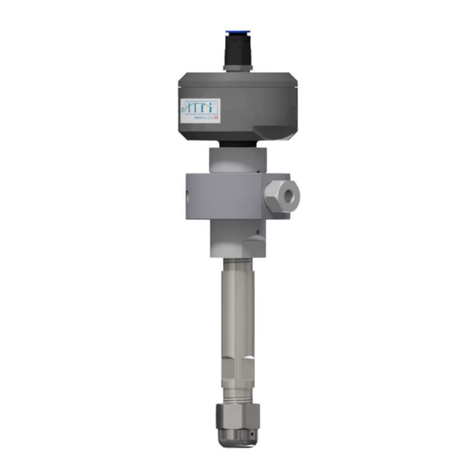
allfi 919115 Manual

Operating and maintenance instruction
Shut-off valve 2.0
(4150 bar / 0,000 psi)
Operating and maintenance instruction
ALLFI AG - Riedenmatt 1 – CH- 370 Stans
Tel.: +41 41 18 05 05 - Fax: +41 41 18 05 10
E-Mail: info@allfi.com - http://www.allfi.com
November 2022

General
2 / 20
Shut-off valve 2.0 (4150 bar / 0,000 psi) 09.01.2023
Scope of application
The present operating and maintenance instruction is valid for:
Shut-off valve 3/8" 2.0 (4150 bar / 0,000 psi)
919115
91911
UH-919115

General
3 / 20
Shut-off valve 2.0 (4150 bar / 0,000 psi) 09.01.2023
Table of contents
1 General .......................................................................................................................................4
1.1 Information on use of the operation and maintenance instruction ......................................4
1.2 Scope of delivery .................................................................................................................4
1.3 Warranty claim ....................................................................................................................4
1.4 Disclaimer............................................................................................................................4
2 Security .......................................................................................................................................5
2.1 Declaration of symbols ........................................................................................................5
2.2 General arning notes ........................................................................................................5
2.3 Intended use .......................................................................................................................6
2.4 Inadmissible usage ..............................................................................................................7
2.5 Residual risks .......................................................................................................................7
2.6 Safety installations ..............................................................................................................8
2.7 Personal protection equipment ...........................................................................................8
2.8 Qualification of the staff ......................................................................................................8
3 Structure and function ................................................................................................................9
3.1 Structure .............................................................................................................................9
3.2 Funktion ..............................................................................................................................9
3.3 Accessories ..........................................................................................................................9
4 General technical data .............................................................................................................. 10
5 Installation and commissioning ................................................................................................. 11
5.1 Fix cutting head to the machine ......................................................................................... 12
5.2 Function check of the shut-off valve .................................................................................. 14
6 Deinstallation ............................................................................................................................ 14
7 Maintenance, Service and Repair .............................................................................................. 15
7.1 Regular maintenance ......................................................................................................... 15
7.2 Reversing (turning) the valve seat ...................................................................................... 16
7.3 Replace seal kit and valve seat ........................................................................................... 17
8 Faults and Troubleshooting ....................................................................................................... 19
8.1 Leakage of the shut-off valve: ............................................................................................ 19
8.2 Further troubleshooting .................................................................................................... 20
9 Recycling ................................................................................................................................... 20
Appendix A – Technical drawing and parts list (shipped with the product)

General
4 / 20
Shut-off valve 2.0 (4150 bar / 0,000 psi) 09.01.2023
1 General
1.1 Information on use of the operation and maintenance instruction
This operation and maintenance instruction is a key part of the product. The information in this manual
is mandatory and must be read and understood by all the persons before operating with the Shut-off
valve 3/8 2.0. The manual must be stored in distance as well as always accessible to the persons,
working with the Shut-off valve 3/8 2.0.
Should you have any questions regarding the content of the manual, please contact the manufacturer
directly.
ALLFI AG - Riedenmatt 1 – CH- 370 Stans
Tel.: +41 41 18 05 05 - Fax: +41 41 18 05 10
E-Mail: info@allfi.com - http://www.allfi.com
1.2 Scope of delivery
The individual parts contained in the shipment can be gathered from the set list in the appendix A
(technical drawing and part list). Upon receipt, the shipment has to be checked of integrity. Possible
detected defectives must be reported immediately to the manufacturer.
1.3 Warranty claim
The ALLFI AG grants warranty for the shipped parts as followed:
Material and manufacturer faults of 12 months from date of delivery or
Defects within the first 2000 hours of operation
Following spare parts are excluded from the warranty:
Seal Kit (consist of Valve needle, HP-seal 2.0, spring & Pressure plate 2.0)
Valve Seat
O-Ring
Valve Case
1.4 Disclaimer
ALLFI AG refuses any claims of liability (material damages, physical injury, as well as disruption of op-
eration), that are a result of disregarding this operating and maintenance instruction.
For example, the damage as a consequence of:
Inadmissible application of the Shut-off valve
Defective maintenance
The disregard of operation instructions
Chemical and electrolytical influences
Use of parts, spare parts, or accessory from a third-party manufacturer
Arbitrary modifications
Not or insufficiently trained staff
The disregard of all these instructions happens on exclusive risk and exclusive responsibility of the cli-
ent. The ALLFI AG is not liable for any production downtimes.

Security
5 / 20
Shut-off valve 2.0 (4150 bar / 0,000 psi) 09.01.2023
2 Security
2.1 Declaration of symbols
This operating and maintenance instruction manual contains important notes and symbols, which are
to be considered and followed. These include:
DA GER
Danger emphasizes operating and service procedures that if not avoided,
may lead to death or serious personal injuries.
WAR I G
Warnings emphasize operating or service procedures, or conditions that
can result in serious personal injury or death.
CAUTIO
Cautions emphasize operating or service procedures, or conditions that
can result in equipment damage or impairment of system operation. If not
avoided, light or medium body injuries could be the consequence.
NOTE
otes provide additional information that can expedite or improve operat-
ing or service procedures.
Danger symbol without key word: Additional notes
2.2 General warning notes
Using of the Shut-off valve, the following warnings are to be considered.
The specified warnings are not only restricted to the operation with the maximal
permissible operating pressure of 4150 bar / 0,000 psi. They are also valid on
work with reduced operation pressures!

Security
/ 20
Shut-off valve 2.0 (4150 bar / 0,000 psi) 09.01.2023
DA GER
Danger of cutting of extremities on contact with waterjet
The contact with the high kinetic energy performing waterjet can have the conse-
quence of cutting of extremities or lead to other injuries.
Therefore:
Operate the machine only, when nobody stands in the danger zone of the
waterjet.
Never touch the waterjet, not even with personal protective equipment.
Always sufficient safety distance during operation of the cutting head.
Never guide the Shut-off valve by hand during operation.
Any injuries in connection with the waterjet, alarm the emergency doctor imme-
diately.
CAUTIO
Danger of breathing difficulties and irritation of the skin and eyes by re-
leased solid particles or dust.
During machining of certain material, solid particles and dust may float in the air,
which could cause breathing difficulties and irritations to the skin and eyes.
Therefore:
Ensure the proper ventilation of the room surrounding the machinery.
Ensure to wear the personal protective equipment (protection glasses,
breathing mask, gloves, …)
Additionally, the rules and regulations of the working place are to be followed to
prevent injuries!
2.3 Intended use
The shut-off valve is designed for shutting off buffer bottles with the purpose of making pressure re-
duction and build-up faster. The shut-off valve must be firmly connected in the machine. Only pure wa-
ter may be used as the working fluid. The technical limits must always be observed. The specifications
for connection assignment must be observed.

Security
7 / 20
Shut-off valve 2.0 (4150 bar / 0,000 psi) 09.01.2023
2.4 Inadmissible usage
Inadmissible usage of the Shut-off valve includes:
The usage of all other fluids other than water
The addition of other substances to the water
Closure of the pressure relief holes
Excessive stress on the shut-off valve
Exceeding permitted limits
Excessive stress on the shut-off valve
Operating the shut-off valve with demounted or disabled technical protection
Likewise, all other uses of the shut-off valve deviating from the intended use are not permitted. All
questions should be addressed directly to the manufacturer.
ALLFI AG - Riedenmatt 1 – CH- 370 Stans
Tel.: +41 41 18 05 05 - Fax: +41 41 18 05 10
E-Mail: info@allfi.com - http://www.allfi.com
2.5 Residual risks
The manufacturer and/or operator of the machine where the shut-off valve is built in, has taken every
precautionary measure possible to reduce residual risks, as far as possible reasonably practicably.
Operation
phase
Damage Danger Reason (possible) measures
Operation
Physical
injuries
Liquids leaking
under high pres-
sure (e.g. at
pressure relief
holes)
Ignoring the torque Follow the torque
Damaged sealing sur-
faces Regular supervision
Busted/Cracked connec-
tions and high-pressure
components as a result
of defects
Protective wall as a tech-
nical protective measure
Flying fragments
Ignoring the torque Follow the torque
Damaged sealing sur-
faces Regular supervision
Busted/Cracked connec-
tions and high-pressure
components as a result
of defects
Protective wall as a tech-
nical protective measure
High kinetic en-
ergy of water jet
Intrusion of extremities
in working area of water
jet
Wearing safety goggles and
other protective equipment
Carry out regular checks
Hearing
damage
Rapidly dis-
charging of fluid Leakage Wear ear protector

Security
8 / 20
Shut-off valve 2.0 (4150 bar / 0,000 psi) 09.01.2023
2.6 Safety installations
The manufacturer or the operator of the full machine, which the shut-off valve is built in, has ensured
the following safety arrangements:
Safety devices to prevent flying fragments or liquids leaking under high pressure
Emergency stoppage to immediately shut down the operating machine
Active: Manually triggered by operator
Passive: Automatically triggered by:
o Failure of high pressure components or gross operating faults
Danger for the operator will arise if safety protections are not functionally, not
followed or evaded anytime. The operator has to ensure the functionality of the
safety protections anytime.
2.7 Personal protection equipment
The operator must offer his staff following protection equipment while he’s working:
Ear protector against:
Noise emissions
Wear protection glasses against:
Fluids and dust particles
Flying fragments
Hand guards against:
Sharp edges of components
Intrusion of micro particles into the skin
Inhalation protection against:
Dust particles, micro particles and spray mist
2.8 Qualification of the staff
The shut-off valve may only be operated and maintained by certified, trained staff.

Structure and function
9 / 20
Shut-off valve 2.0 (4150 bar / 0,000 psi) 09.01.2023
3 Structure and function
3.1 Structure
1. Pneumatic Cylinder 2.0
2. Seal Kit 2.0
2.1. Valve needle
2.2. Pressure plate 2.0
2.3. HP-seal 2.0
2.4. Compression Spring
3. Coupling Ring
4. Valve Seat
5. Adapter 3/8" to Valve Case
. O-Ring
7. Reduction m/f
8. Valve case 2.0
3.2 Funktion
The shut-off valve is a high-pressure needle valve and is actuated pneumatically. It is closed by com-
pressed air and a pneumatic piston actuator and opened by spring force. The compressed air supply
is switched on and off by a controlled valve (not included in the scope of delivery). For information on
the maximum permissible operating pressure of the water, see chapter 4.
3.3 Accessories
Article: Ejector mandrel DX Paste P-Paste
Article no: 900070 051055 0510 5
Function: Replace Seal Kit and
Valve Seat
Greasing screw connections
and metallic contact areas for
standard applications
Greasing screw connec-
tions and metallic contact
areas for food safe

General technical data
10 / 20
Shut-off valve 2.0 (4150 bar / 0,000 psi) 09.01.2023
All accessories for metric cutting heads are included in case set 882101
All accessories for imperial cutting heads are included in case set 882101-I
4 General technical data
Pneumatic pressure: - 7 bar / 87 psi – 102 psi
Minimum working pressure: 0 bar / 0 psi
Maximal working pressure: 4150 bar / 0,000 psi
Connection lines: Appendix A
Nominal size (DN) 1mm
Pressure loss coefficient (l/min & bar) 0.51
Maximal working temperature: 50 °C
Maximum transport and storage temperature: 0 °C
Reaction time: up to 1 switching cycles per seconds
Weight: ca. 1.5 kg
Requested water quality:
Water parameter Unit Value
Electrical Conductivity µS / cm 100 – 450
PH-value - 7.0 - 8.5
Total hardness °dH 2.0 - 10.0
Carbonate hardness
(acid capacity pH 4.3)
°dH 2.0 - 10.0
Degree of alkalinity pH 8.2 mmol / l 0 - 0.25
Chloride mg / l ≤ 50
Iron mg / l ≤ 0.2
Manganese mg / l ≤ 0.05
Copper mg / l ≤ 2.0
Silicate mg / l ≤ 5.0
(Filtrate-) solid content mg / l ≤ 350
Article: Torque wrench Open end fitting Mounting tool for
O-ring
Article no: 0004 8 AF 17 – 000339
AF 22 – 000272
AF 24 – 000280
AF 27 – 000511
040011
Function: Tightens screws with a
specific torque
O-ring assembly and dis-
assembly

Installation and commissioning
11 / 20
Shut-off valve 2.0 (4150 bar / 0,000 psi) 09.01.2023
Technical data as dimensions can be found in the technical drawing in appendix A.
5 Installation and commissioning
WAR I G
Risk of injury: It is forbidden to close the pressure relief holes.
By closing the pressure relief holes, the shut-off valve or parts of it may explode.
Therefore: Never close or cover any pressure relief hole.
Positions of the pressure relief holes:
General installation tip:
Use of a pneumatic oiler is forbidden.
Compressed air filter with water separator must be installed.
Compressed air filter and pneumatic valve must have a minimum nominal flow
rate of 5 m
3
/h.
Absolute cleanliness of the pipes is important before connection.
Follow the steps below for installation.
If you are installing the program for the first time, follow the corresponding sub-
chapters step by step.

Installation and commissioning
12 / 20
Shut-off valve 2.0 (4150 bar / 0,000 psi) 09.01.2023
NOTE
Material damage as a result of pitting
Not or insufficient greased threads or contact areas can pit.
Therefore:
Always grease threads and metallic contact areas. Check appendix A for addi-
tional information.
NOTE
Material damage or leakage as a result of fouling
Fouling components, especially at threads, can lead to leakages and damage.
Therefore:
Pay attention to the cleanliness of the components while maintaining.
NOTE
Material damage as a result of leakages
Constant leakage may damage the product.
Therefore:
Immediately eliminate leakages (see chapter 8 „Faults and Troubleshooting”).
5.1 Fix cutting head to the machine
The shut-off valve must be connected to the machine at the mounting ring. Other fastening possibili-
ties must be discussed with the manufacturer.
During installation, ensure that none of the pressure relief holes are closed!

Installation and commissioning
13 / 20
Shut-off valve 2.0 (4150 bar / 0,000 psi) 09.01.2023
1. Unscrew the gland nut from
the coupling ring.
2. Remove collar from gland
nut.
3. Slide the gland nut over the
HP tube.
4. Screw the collar on the HP
tube (left-handed thread).
There must be 1 or 2 convo-
lutions visible between the
conus and the pressure ring.
Fix coupling ring on mounting plate
with three M screws
Hole pattern see appendix A
(Exemplary drawing)
5. Mount shut-off valve on the
machine.

Deinstallation
14 / 20
Shut-off valve 2.0 (4150 bar / 0,000 psi) 09.01.2023
. Connect the HP tube with the
shut-off valve
torque see appendix A.
7.
Plug in compressed air con-
nection by snapping in.
5.2 Function check of the shut-off valve
Close and open the shut-off valve several times under operating conditions (water pressure = operat-
ing pressure). Check the following points:
Error-free opening and closing
No delays in opening and closing
Tightness
If all the points checked are functioning correctly, the shut-off valve is ready for normal operation. If
any defects are found, please refer to chapter 8 "Malfunctions and troubleshooting".
6 Deinstallation
Before uninstalling the shut-off valve, release pressure from the HP tubes and protect
against unexpected re-pressurizing.
1. Remove pneumatic hose.
2. Remove HP tube.
3. Remove shut-off valve from the machine
6
7
2
6
2
1

Maintenance, Service and Repair
15 / 20
Shut-off valve 2.0 (4150 bar / 0,000 psi) 09.01.2023
7 Maintenance, Service and Repair
Before uninstalling the shut-off valve, release pressure from
the HP tube and protect against unexpected re-pressurizing.
The shut-off valve must be removed from the machine for maintenance, servicing and repair work ac-
cording to chapter .
All maintenance, service and repair work not written in this document has to be executed by the manu-
facturer.
NOTE
Material damage or leakage as a result of fouling
Dirty components, especially considering the threads, may lead to leakages and
damage of the shut-off valve.
Therefore:
Ensure a proper cleaning of the components.
NOTE
Property damage as a result of pitting
Threads that are not greased or insufficiently greased may pit.
Therefore:
Always grease threads and metallic contact areas. Check appendix A for addi-
tional information.
7.1 Regular maintenance
What Through whom When
Check tightness
see also 8.1 Operator daily
Check valve for heat generation
See also 8.2
Operator daily

Maintenance, Service and Repair
1 / 20
Shut-off valve 2.0 (4150 bar / 0,000 psi) 09.01.2023
7.2 Reversing (turning) the valve seat
Reason: Valve seat leaking
1
1. Removing the shut-off valve from
the machine is recommended
(Chapter )
2. Screw adapter out of valve case
Attention! Counter hold the
valve case AF 24
2
1. Remove the O-ring from valve case
with help of tool 040011
2. Remove the valve seat from the valve
case. Note the orientation of groove of
the valve seat (top or bottom).
3
When groove was on top:
Valve seat can be reinstalled with groove
at the bottom.
When groove was on bottom:
Now that both seats are worn out, valve
seat must be replaced with new one and
installed with groove on top.
It is recommended to change the seal kit
as well. (See chapter 7.3)
4
1. Insert O-ring into valve case using as-
sembly tool 040011
2. Screw adapter into valve case and
tighten (torque see appendix A). At-
tention! Counterhold on valve case
AF24.
3. Fix shut-off valve to the machine.
(Chapter 5.1)
4. Shut-off valve function check (chapter
5.2).
Groove
on top
Groove on
bottom
2

Maintenance, Service and Repair
17 / 20
Shut-off valve 2.0 (4150 bar / 0,000 psi) 09.01.2023
7.3 Replace seal kit and valve seat
Reason: High pressure seal leaking
1
1. Removing the shut-off valve
from the machine is recom-
mended (Chapter )
2. Screw adapter out of valve
case Attention! Counter hold
the valve case AF 24
2
1. Remove the O-ring from valve
case with help of tool 040011
2. Remove the valve seat from the
valve case. Note the orientation of
the groove of the valve seat for
step 7 (top or bottom).
3
1. Clamp pneumatic cylinder at the
width across flats in a bench vise.
Attention! Do not over tighten,
this would deform the cylinder.
Use protective jaws.
2. Unscrew valve case at the AF 24.
4
1. Sit valve case on a solid surface
according illustration (needle point
face up).
2. Press the seal kit with the ejector
mandrel 900070 out of the valve
case.
3. Dispose/recycle the old seal kit.
Groove
on top
Groove on
bottom
2

Maintenance, Service and Repair
18 / 20
Shut-off valve 2.0 (4150 bar / 0,000 psi) 09.01.2023
5
1. Grease the outer cone and the
pressure surface of the support
disc of the new seal kit according
to Appendix A.
2. Place the new seal kit on the
pneumatic cylinder.
1. Grease the thread of the cylinder ac-
cording to appendix A.
2. Screw valve case (AF24) on pneu-
matic cylinder and tighten (torque see
appendix A).
7
1. If valve seat in step 2 with groove
on top:
- Turn the valve seat and install it
with the groove at the bottom.
2. If valve seat in step 2 with groove
at bottom:
- Replace the valve seat and in-
stall the new one with groove at
the top.
3. Insert the O-ring into the valve
seat using mounting tool 040011
8
1. Grease the adapter on the
thread according to Appendix
A.
2. Screw adapter into valve case
and tighten (torque see appen-
dix A). Attention! Counterhold
on valve case AF24.
3. Mount shut-off valve to the ma-
chine (chapter 5.1).
4. Shut-off valve function check
(chapter 5.2).
2

Faults and Troubleshooting
19 / 20
Shut-off valve 2.0 (4150 bar / 0,000 psi) 09.01.2023
8 Faults and Troubleshooting
Before uninstalling the shut-off valve, release pressure from
the HP tube and compressed air tube.
Protect against unexpected re-pressurizing.
NOTE
Material damage as a result of leakages
Constant leakage may damage the product.
Therefore:
Immediately eliminate leakages.
Warning! After any troubleshooting, shut-off valve function check (chapter 5.2).
8.1 Leakage of the shut-off valve:
3
1
5
4
2
2

Recycling
20 / 20
Shut-off valve 2.0 (4150 bar / 0,000 psi) 09.01.2023
Pos. of the leak-
age Cause of the leakage Action Chapter
1
Seal kit
(Check twice if the
leakage is not at po-
sition 2)
HP-Sealing damaged Replace seal kit
7.3
Seal cone in valve case or
Pressure platedamaged
Replace damaged parts
Wrong torque for the pneu-
matic cylinder
Use correct torque according ap-
pendix A
Water pressure to high Please note operating limits 4
2
HP screw con-
nection
Wrong torque for HP screw
connection
Tight HP screw connection accord-
ing appendix A 5.1
Seal cone of HP tube dam-
aged Recut the cone of the HP tube
3
Seal cone valve
case – valve seat
Wrong torque for adapter Tight adapter according appendix
A 7.2
Seal cone damaged Replace valve seat and/or valve
case 7.3
4
Seal cone
adapter
- v
alve
seat
Wrong torque for adapter Tight adapter according appendix
A 7.2
Seal cone damaged Replace valve seat and/or valve
case
5
Seal cone re-
ducer coupling –
valve seat
Wrong torque for adapter Tight adapter according appendix
A
Seal cone damaged Replace valve seat and/or valve
case
8.2 Further troubleshooting
Error Possible causes Action Chapter
Shut-off valve does
not close
To low air pressure Take into account
operating limits
4
Valve Seat or needle damaged 7.2 /7.3
Foreign body in the valve seat
Shut-off valve be-
comes warm
Valve does not close properly (leaking at
needle seat)
possible causes see above
(shut-off valve does not close)
9 Recycling
The shut-off valve is made of metal and plastic. All the metal parts can be recycled. The plastic parts
are to be professionally recycled as per local specifications.
This manual suits for next models
2
Table of contents
Other allfi Control Unit manuals
Popular Control Unit manuals by other brands

DuraComm
DuraComm DC-RMCU1 owner's guide

Aqua-Scope
Aqua-Scope KFRLWE01 Installation

Hearth and Home Technologies
Hearth and Home Technologies WFM-RETROFIT installation instructions

Texas Instruments
Texas Instruments 990 Maintenance manual
Jafar
Jafar 7010 Operation and maintenance manual

RAK
RAK RAK3172 quick start guide
Future Design
Future Design VR18 Installing and Removing
Fuji Electric
Fuji Electric MICREX-SX Series SPH user manual

Rockwell Automation
Rockwell Automation ControlLogix 1756-HYD02 user manual

Danfoss
Danfoss OPTYMA user guide
BENDIX
BENDIX PP-7 TRAILER SUPPLY VALVE manual
Baker Hughes
Baker Hughes Masoneilan MiniTork II 37002 Series instruction manual
