PSG Wilden XSD HS Series Instruction Manual

XSD HS
Sanio™Hygienic Series
Surge Dampener
WIL-12230-E-04
REPLACES WIL-12230-E-03
Where Innovation Flows
www.wildenpump.com
EOM
Engineering
Operation &
Maintenance

Section 1 cautions—Read FiRst! .............................................1
Section 2 Wilden PumP designation system ................................2
Section 3 HoW it WoRks—PumP & aiR distRibution system. . . . . . . . . . . . . . . .3
Section 4 dimensional dRaWings.............................................4
Section 5 PeRFoRmance
XSD1-1/2 HS .............................................................5
XSD2 HS ................................................................6
XSD3 HS ................................................................7
Section 6 suggested installation & tRoublesHooting ....................9
Section 7 disassembly / Reassembly ........................................11
Reassembly Hints & Tips..................................................14
Cleaning-CIP ............................................................15
Section 8 exPloded VieW & PaRts listing
XSD1-1/2 HS ............................................................16
XSD2 HS ...............................................................18
XSD3 HS ...............................................................20
Section 9 elastomeR oPtions ................................................22
table oF contents

WIL-12230-E-04 1 WILDEN PUMP & ENGINEERING, LLC
CAUTION: Do not over-lubricate air supply —
excess lubrication will reduce performance.
CAUTION: Do not exceed 8.6 bar (125 psig) air
supply pressure.
CAUTION: When choosing dampener materials,
be sure to check the temperature limits for
all wetted components. Example: Viton®
has a maximum limit of 177°C (350°F) but
polypropylene has a maximum limit of only 79°C
(175°F).
CAUTION: Maximum temperature limits are
based upon mechanical stress only. Certain
chemicals will significantly reduce maximum
safe operating temperatures. Consult Chemical
Resistance Guide (E4) for chemical compatibility
and temperature limits.
TemperATUre LImITs:
Polypropylene 0°C to 79°C 32°F to 175°F
PVDF –12°C to 107°C 10°F to 225°F
PFA 7°C to 107°C 20°F to 225°F
Neoprene –18°C to 93°C 0°F to 200°F
Buna-N –12°C to 82°C 10°F to 180°F
EPDM –51°C to 138°C –60°F to 280°F
Viton®FKM –40°C to 177°C –40°F to 350°F
Wil-Flex™ –40°C to 107°C –40°F to 225°F
Saniflex™ –29°C to 104°C –20°F to 220°F
Polyurethane –12°C to 66°C 10°F to 150°F
Polytetrafluoroethylene (PTFE)
14°C to 104°C 40°F to 220°F
Nylon –18°C to 93°C 0°F to 200°F
Acetal –29°C to 82°C –20°F to 180°F
SIPD PTFE
with
Neoprene-backed
4°C to 104°C 40°F to 220°F
SIPD PTFE
with
EPDM-backed
–10°C to 137°C 14°F to 280°F
Polyethylene 0°C to 70°C 32°F to 158°F
Geolast®–40°C to 82°C –40°F to 180°F
NOTE: Not all materials are available for all
models. Refer to Section 2 for material options
for your dampener.
WArNING: Prevent static sparking. If static
sparking occurs, fire or explosion could result.
Dampener, pump, valves and containers must
be grounded to a proper grounding point
when handling flammable fluids and whenever
discharge of static electricity is a hazard.
CAUTION: The process fluid and cleaning fluids
must be chemically compatible with all wetted
dampener components. Consult Chemical
Resistance Guide (E4).
CAUTION: Dampener(s) should be thoroughly
flushed before installing into process lines.
FDA- and USDA-approved dampeners should be
cleaned and/or sanitized before being used.
CAUTION: Always wear safety glasses when
operating dampener. If diaphragm rupture occurs,
process fluid may be forced out air exhaust.
CAUTION: Before any maintenance or repair
is attempted, the compressed air line to the
dampener and pump should be disconnected
and all air pressure allowed to bleed from the
system. Disconnect all intake, discharge and air
lines. Drain the dampener by allowing any fluid
to flow into a suitable container.
CAUTION: Blow out air line for 10 to 20 seconds
before attaching to dampener to make sure all
pipeline debris is clear. Use an in-line air filter. A
5µ (micron) air filter is recommended.
CAUTION: Dampeners cannot be used in
submersible applications.
CAUTION: Tighten all hardware prior to
installation.
CAUTION: ATEX products have been assessed
for use in potentially explosive atmospheres in
accordance with the European Directive 94/9/
EC (ATEX 95). Users of ATEX products must
be familiar with ATEX requirements and follow
all safety guidelines. (Refer to Wilden Safety
Supplement WIL-18510-E.)
1
4°C to 149°C (40°F to 300°F) - 13 mm (1/2") and 25 mm (1") models only.
Section 1
cautions—Read FiRst!

Wilden PumP & engineering, llC 2 Wil-12230-e-04
Section 2
WildeN desigNatioN system
Xsd
HygieNiC seRies
eQUaliZeR®
legeNd
Xsd X / XX XX /XXX /xxxx
eQUaliZeR
®
sURge
damPeNeR diaPHRagm
RegUlatoR Body
aiR CHamBeR
Wetted PaRts / oUteR PistoN
iNlet siZe
sPeCialty Code
(if applicable)
sPeCialty Codes
mateRial Codes
model
XSD = ATEX EQUALIZER
®
SURGE DAMPENER
iNlet siZe
1-1/2 = 38 mm (1-1/2”)
2 = 51 mm (2”)
3 = 76 mm (3”)
Wetted PatH /
oUteR PistoN
SS = STAINLESS STEEL/
STAINLESS STEEL
SZ = STAINLESS STEEL/
NO PISTON
aiR CHamBeR
N = NICKEL-PLATED
ALUMINUM
S = STAINLESS STEEL
RegUlatoR Body
N = NICKEL-PLATED
ALUMINUM
S = STAINLESS STEEL
diaPHRagm
BNU = ULTRA-FLEX™ BUNA1
EPU = ULTRA-FLEX™ EPDM1
FBS = SANITARY BUNA1
(Two Yellow Dots)
FES = SANITARY EPDM1
FSS = SANIFLEX™ 1
FWL = FULL STROKE SANITARY
WIL-FLEX™ IPD1,2,3
FWS = SANITARY WIL-FLEX™ 1
LEL = PTFE-EPDM BACKED
LAMINATE IPD1,2,3
TEU = PTFE W/EPDM
BACKUP1,2
TSU = PTFE W/SANIFLEX™
BACK-UP1,2
0770 SaniFlo®HS
NOTE: MOST ELASTOMERIC MATERIALS USE COLORED DOTS FOR IDENTIFICATION.
Viton®is a registered trademark of DuPont Elastomers.
Santoprene®is a registered trademark of Exxon Mobil Corporation.
NOTE:
1Meets requirements of FDA CFR21.177
2Meets of USP Class VI
3Required for EHEDG certification

Maximum temperature limits are based upon
mechanical stress only. Certain chemicals will
significantly reduce maximum safe operating
temperatures. Consult Wilden Chemical Guide for
chemical compatibility and temperature limits. Plastic
Equalizers are manufactured with virgin plastic and
are not UV-stabilized. Direct sunlight for prolonged
periods can cause deterioration of these plastics. In
this situation a metal Equalizer®is suggested.
Wear safety glasses. When diaphragm rupture occurs,
material being pumped may be forced out air exhaust.
WARNING Prevent static sparking. If static sparking
occurs, fire or explosion could result. Pump, Equalizer®,
valves and containers must be grounded when
handling flammable fluids and whenever discharge of
static electricity is a hazard.
caution: Do not exceeD 8.6 bar (125 psig) air pressure.
A compressed air line attached to the air regulator body sets
and maintains pressure on the air side of the diaphragm. As the
reciprocating pump begins its stroke, liquid discharge pressure
increases which flexes the Equalizer®diaphragm inward. This
action accumulates fluid in the liquid chamber (see Phase 2).
When the pump redirects its motion upon stroke completion,
the liquid discharge pressure decreases and compressed air
in the air side forces the Equalizer®diaphragm to flex outward
displacing the fluid into the discharge line (see Phase 3). This
motion provides the supplementary pumping action needed to
minimize pressure fluctuation.
Section 3
How It works—DAMPENEr
The Equalizer®automatically sets and maintains the correct air
pressure matching the variations in liquid flow or discharge
pressure generated by the pump. A shaft attached to the Equalizer®
diaphragm triggers the addition or deletion of the air within the
non-wetted side of the Equalizer®. The Equalizer®automatically
adjusts to any pressure and/or flow setting of the pump with
no need for manual adjustment of the unit and/or system. The
Equalizer®has proven to be the cost effective choice for protecting
your liquid process system from unwanted pulsation or pressure
fluctuation. Contact your local Wilden distributor for further
information on the Equalizer®and other pumping solutions.
All reciprocating pumps experience a pressure fluctuation. The
Equalizer®minimizes unwanted pressure fluctuation by providing
a supplementary pumping action. This is accomplished by using
a diaphragm as a separation membrane within the Equalizer®to
trap a given volume of liquid on one side and pressurized air on the
other. When the fluid pressure falls in the system, the Equalizer®
supplies additional pressure to the discharge line between
pump strokes by displacing fluid via diaphragm movement. This
movement provides the supplementary pumping action needed
to virtually eliminate pressure variation and pulsation.
AIR
REGULATOR
BODY
AIR
REGULATOR
BODY
AIR
REGULATOR
BODY
LIQUID SIDE LIQUID SIDE LIQUID SIDE
DIAPHRAGM DIAPHRAGM DIAPHRAGM
AIR
SIDE
AIR
SIDE
AIR
SIDE
AIR
REGULATOR
BODY
AIR
REGULATOR
BODY
AIR
REGULATOR
BODY
LIQUID SIDE LIQUID SIDE LIQUID SIDE
DIAPHRAGM DIAPHRAGM DIAPHRAGM
AIR
SIDE
AIR
SIDE
AIR
SIDE
AIR
REGULATOR
BODY
AIR
REGULATOR
BODY
AIR
REGULATOR
BODY
LIQUID SIDE LIQUID SIDE LIQUID SIDE
DIAPHRAGM DIAPHRAGM DIAPHRAGM
AIR
SIDE
AIR
SIDE
AIR
SIDE
PHAsE 1 PHAsE 3PHAsE 2
WIL-12230-E-04 3 WILDEN PUMP & ENGINEERING, LLC

WILDEN PUMP & ENGINEERING, LLC 4 WIL-12230-E-04
Section 4
DIMENSIONAL DRAWINGS
XSD1-½ SanifloTM HS
XSD2 SanifloTM HS
DIMENSIONS
ITEM METRIC (mm) STANDARD (inch)
A 284 11.2
B 259 10.2
C 160 6.3
D 305 12.0
E 320 12.6
DIMENSIONS
ITEM METRIC (mm) STANDARD (inch)
A 292 11.5
B 259 10.2
C 170 6.7
D 305 12.0
E 338 13.3
XSD3 SanifloTM HS
DIMENSIONS
ITEM METRIC (mm) STANDARD (inch)
A 358 14.1
B 312 12.3
C 241 9.5
D 363 14.3
E 482 19.0

WIL-12230-E-04 5 WILDEN PUMP & ENGINEERING, LLC
Section 5
XSD1½ HS PERFORMANCE
These charts show discharge head fluctuations for
a diaphragm pump with and without a dampener.
By reviewing the variation in pressure, the level of
dampening can be estimated for an application. For
example, the head pressure generated by a 38 mm
(1-1/2")” pump operating at 6.8 bar (100 psig) air
inlet pressure and 6.2 bar (90 psig) head pressure
varies between 0.8 bar (12 psig) and 7.4 bar (108 psig)
resulting in a total pressure fluctuation of 96 psig
for each stroke. When an XSD1 1/2/SZSS/LEL/0770
dampener is installed in the application, the head
pressure varies between 5.1 bar (74 psig) and 6.8 bar
(99 psig) resulting of a pressure fluctuation of only 1.7
bar (25 psig). This results in a 74% reduction in head
pressure fluctuation.

WILDEN PUMP & ENGINEERING, LLC 6 WIL-12230-E-04
XSD2 HS PERFORMANCE
These charts show discharge head fluctuations for
a diaphragm pump with and without a dampener.
By reviewing the variation in pressure, the level of
dampening can be estimated for an application.
For example, the head pressure generated by a 51
mm (2") pump operating at 6.8 bar (100 psig) air
inlet pressure and 6.2 bar (90 psig) head pressure
varies between 1.4 bar (20 psig) and 7 bar (102 psig)
resulting in a total pressure fluctuation of 5.7 bar
(82 psig) for each stroke. When an XSD2/SZSS/
LEL/0770 dampener is installed in the application, the
head pressure varies between 5.2 bar (75 psig) and
6.8 bar (100 psig) resulting of a pressure fluctuation of
only 1.7 bar (25 psig). This results in a 70% reduction
in head pressure fluctuation.

WIL-12230-E-04 7 WILDEN PUMP & ENGINEERING, LLC
XSD3 HS PERFORMANCE
These charts show discharge head fluctuations for
a diaphragm pump with and without a dampener.
By reviewing the variation in pressure, the level of
dampening can be estimated for an application. For
example, the head pressure generated by a 76 mm (3")
pump operating at 6.8 bar (100 psig) air inlet pressure
and 6.2 bar (90 psig) head pressure varies between 1.4
bar (21 psig) and 7.1 bar (103 psig) resulting in a total
pressure fluctuation of 82 psig for each stroke. When
an XSD3/SZSS/LEL/0770 dampener is installed in the
application, the head pressure varies between 4.9 bar
(71 psig) and 6.5 bar (94 psig) resulting of a pressure
fluctuation of only 1.6 bar (23 psig).This results in a 72%
reduction in head pressure fluctuation.

NOTES

WIL-12230-E-04 9 WILDEN PUMP & ENGINEERING, LLC
The model XSD1-1/2 Hygienic Series™ has a 38 mm (1-1/2”)
tri clamp style inlet/discharge. The model XSD2 has a 51 mm
(2”) inlet/discharge. The model XSD3 has a 76 mm (3”) inlet/
discharge. The Equalizer®can be installed in either direction.
A variety of materials are available to satisfy temperature,
chemical compatibility, abrasion and flex concerns. The
Equalizer®installed on the discharge side of the pump
minimizes pulsation and protects in-line equipment. It can also
be connected on the suction side to prevent water hammer
associated with a positive inlet condition. The model XSD1-1/2
Hygienic Series™ is engineered for use with Wilden 38 mm (1-
1/2”) PX4 Hygienic Series™ pumps. The model XSD2 Hygienic
Series™ is engineered for use with Wilden 51 mm (2”) PX8
Hygienic Series™ pumps. The model XSD3 is engineered for
use with Wilden PX15 Hygienic Series™ pumps.
Install the Equalizer®as shown above. The use of flexible
connections and a Filter, Regulator, Lubricator (FRL) will extend
parts life on the. Shut-off valves on the suction side of pump
and the discharge side of Equalizer®will enable maintenance
personnel to safely service the equipment. To maximize
effectiveness install the Equalizer®as close as possible to the
discharge of the pump. It is important to support the pipe
immediately downstream from the Equalizer®. Use a tee
connector on the pump air supply line and connect the line to
the Equalizer®regulator body. This tee connector should be
installed after the FRL. The Equalizer®consumes very little air,
therefore, a 1/4” hose is more than adequate to supply enough
air volume. When the air supply to the pump is shut down, the
air to the Equalizer®will be shut off as well.
Section 6
SuggeSted InStallatIon

WILDEN PUMP & ENGINEERING, LLC 10 WIL-12230-E-04
tRouBleSHootIng
1) When there is a significant drop in the fluid discharge
pressure, there will be a noticeable release of air
through the small bleed hole in the air regulator body.
This is how the Equalizer®automatically adjusts itself
for optimal suppression. This is a good way of verifying
proper operation of the unit. If there is a continuous
discharge of air out this hole during steady fluid
discharge pressure, the Equalizer®is not functioning
properly and should be inspected. The air regulator
body houses three (3) Glyd rings.
2) Fluid leakage around the clamp band area is normally
stopped by tightening the clamp band bolts. If
leakage continues, unit should be disassembled and
inspected.
3) Air leakage between the adapter plate and air chamber
requires tightening of four air chamber bolts on the
inside of the air chamber.

WIL-12230-E-04 11 WILdEn PumP & EngInEErIng, LLC
Tools Required:
• Deepwellsocketand
ratchet(3/4”)
• Deadblowmallet
• Hex(Allen®)wrenches
(3/16”and1/4”)
• Largeadjustable
wrenchorchannel
lockpliers
Tools
Recommended:
• Largepipewrench
• Viseequipped
w/softjaws(such
asaluminum,plastic,
plywoodorother
suitablematerial)
CAUTION: Beforeanymaintenanceorrepairisattempted,thecompressedairline
totheEqualizer®andthepumpshouldbedisconnectedandallairpressureallowed
tobleedfromthesystem.Disconnectallintake,dischargeandairlines.Beaware
of any hazardous effects of contact with your process uid. PLEASE READ ALL
DIRECTIONSBEFORESTARTINGDISASSEMBLY.
NOTE: The model photographed for these instructions is a XSD1-1/2 Hygienic
Series.OtherEqualizer®modelsshouldbesimilarindesignbutmaycontainslightly
differentcomponentsandfastenersizes.
Step 1
Removelargeclampband.
Step 2
Setliquidchamberaside.
Step 3
Remove reducer bushing at top of
regulator.
Section 7
SURGE DAMPENER DISASSEMBLY

WILdEn PumP & EngInEErIng, LLC 12 WIL-12230-E-04
SURGE DAMPENER DISASSEMBLY
Step 4
Loosen shaft assembly by using
a 3/4” socket on shaft bolt inside
air regulator body. Turn counter
clockwise.Oneoftwoscenarioswill
occur: the diaphragm will loosen
from shaft, or the shaft bolt will
loosenfromshaft.
Step 5
In either case, this will allow the
removal of the diaphragm, shaft
stop, shaft, shaft stop washer and
bolt.
Step 6
Inspect shaft for nicks or abrasion.
Smallnickscanusuallybedressed
out.Ifshaftischemicallyattackedor
nicksarehinderingoperation,shaft
shouldbereplaced.
Step 7
Disassembly of the air chamber
from the regulator adaptor plate
is needed only in the event of air
leakage.
Step 8
Intheevent of an airleak,remove
the air chamber and replace the
gasket.
Step 9
Disassembly of the regulator body
from the regulator adaptor plate
is needed only in the event of air
leakage.

WIL-12230-E-04 13 WILdEn PumP & EngInEErIng, LLC
Step 10
Intheevent of an airleak,remove
the regulator adaptor plate and
replacetheO-ring.
Step 11
Using an O-ring pick remove the
Glyd-ringsfromairregulatorbody.
SURGE DAMPENER DISASSEMBLY
WILdEn PumP & EngInEErIng, LLC 14 WIL-12230-E-04
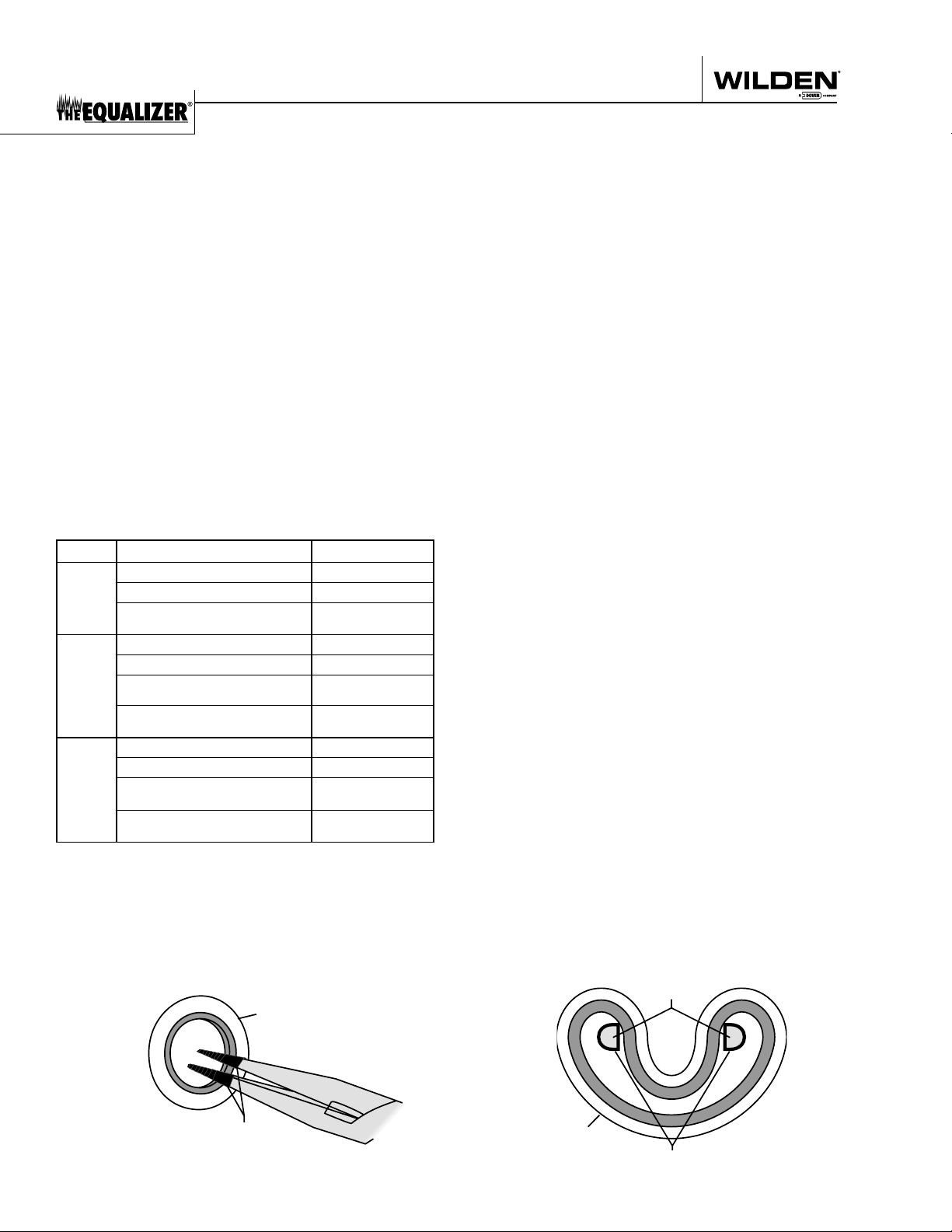
REASSEMBLY HINTS & TIPS
Figure A
SHAFT SEAL
TAPE
Figure B
SHAFT SEAL
TAPE
NEEDLE NOSE
PLIERS
ASSEmbly:
Upon performing applicable maintenance to the
air distribution system, the Equalizer® can now
be reassembled. Please refer to the disassembly
instructions for photos and parts placement. To
reassemble the Equalizer®, follow the disassembly
instructions in reverse order. The air regulator body
needs to be assembled rst, then the diaphragms
andnallythewettedpath.Pleasendtheapplicable
torquespecicationsonthispage.Thefollowingtips
willassistintheassemblyprocess.
• Lubricate air regulator body, Glyd rings and shaft
bore, center with NLGI grade 2 white EP bearing
greaseorequivalent.
• Cleantheinsideoftheairregulatorbodyboreto
ensurenodamageisdonetonewshaftseals.
• Stainless bolts should be lubed to reduce the
possibilityofseizingduringtightening.
mAXImUm TORQUE SPECIFICATIONS
Model Description of Part Torque
XSD1-½ HS
Air chamber/adapter plate 24.4 N·m (18 ft-lb)
Air regulator body/adapter plate 7.9 N·m (70 in-lb)
Outer piston/shaft bolt assembly
(all diaphragms) 54.2 N·m (40 ft-lb)
XSD2 HS
Air chamber/adapter plate 24.4 N·m (18 ft-lb)
Air regulator body/adapter plate 7.9 N·m (70 in-lb)
Outer piston/shaft bolt assembly
(rubber & PTFE) 109 N·m (80 ft-lb)
Outer piston/shaft bolt assembly
(Ultra-Flex™ & SIPD) 74.6 N·m (55 ft-lb)
XSD3 HS
Air chamber/adapter plate 24.4 N·m (18 ft-lb)
Air regulator body/adapter plate 7.9 N·m (70 in-lb)
Outer piston/shaft bolt assembly
(rubber & PTFE) 109 N·m (80 ft-lb)
Outer piston/shaft bolt assembly
(Ultra-Flex™ & SIPD) 74.6 N·m (55 ft-lb)
SHAFT SEAl INSTAllATION:
PRE-INSTAllATION
• Once all of the old seals have been removed, the
insideoftheairregulatorbodyshouldbecleaned
toensurenodebrisisleftthatmaycausepremature
damagetothenewseals.
INSTAllATION
Thefollowingtoolscanbeusedtoaidintheinstallation
ofthenewseals:
NeedleNosePliers
PhillipsScrewdriver
ElectricalTape
• Wrapelectricaltapearoundeachlegoftheneedlenose
pliers(heatshrinktubingmayalsobeused).Thisisdone
topreventdamagingtheinsidesurfaceofthenewseal.
• Withanewsealinhand,placethetwolegsoftheneedle
nosepliersinsidethesealring.(SeeFigureA.)
• Openthepliersaswideasthesealdiameterwillallow,
thenwith twongers pulldownon the topportionof
thesealtoformkidneybeanshape.(SeeFigureB.)
• Lightly clamp the pliers together to hold the seal into
thekidneyshape.Besuretopullthesealintoastight
ofakidneyshapeaspossible,thiswillallowthesealto
traveldownthebushingboreeasier.
• Withthesealclampedinthepliers,insertthesealinto
the bushing bore and position the bottom of the seal
intothecorrectgroove.Oncethebottomofthesealis
seatedinthegroove,releasetheclamppressureonthe
pliers.Thiswillallowthesealtopartiallysnapbacktoits
originalshape.
• After the pliers are removed, you will notice a slight
bumpinthesealshape.Beforethesealcanbeproperly
resized, the bump in the seal should be removed as
much as possible. This can be done with either the
Phillipsscrewdriveroryournger.Witheithertheside
of the screwdriver or your nger, apply light pressure
to the peak of the bump. This pressure will cause the
bumptobealmostcompletelyeliminated.
• Lubricate the edge of the shaft with NLGI grade 2
whiteEPbearing
grease.
• Slowly insert the center shaft with a rotating motion.
Thiswillcompletetheresizingoftheseal.
• Performthesestepsfortheremainingseal.

WIL-12230-E-04 15 WILdEn PumP & EngInEErIng, LLC
Section 8
CLEANING - CIP
Thedesignofthepulsationdampenerallowsforease
ofcleaning.Thisequipmentcanbedisassembledfor
cleaning or cleaned in place without disassembly if
the user has an appropriate CIP system. Before any
cleaningisattempted,ensurethatthecleaninguids
arecompatiblewithallwettedcomponents.
For best cleaning results consider the following
information prior to cleaning of the dampener.
• For best Clean in Place (CIP) results, the pulsation
dampener should be congured to the EHEDG
conguration.
• Actual CIP effectiveness and processes should
be validated on location by the end user’s quality
assurance personnel or meet internal guidelines.
Postcleaningswabtestisonemethodtoaccomplish
this.
• The user should establish periodic inspections
withfullteardowntoverifythattheCIPprocesses
continuetobeeffectiveasrstvalidated.
• When CIP pressures are greater than 10 psig (0.7
bar), the dampener should be pre-loaded with air
pressuretobalancetheCIPpressureinthepulsation
dampenerinordertomaximizediaphragmlife.
The following are some details to consider when
cleaning the pulsation dampener.
• Through the EHEDG certication process, the
dampenerhasbeenvalidatedtocleanequivalentto
theinlettubingofthesamediameter.Thecleaning
chemicalsuppliershouldbeconsultedandadvised
of this for their chemical solution and application.
Thesameguidelinesfordurationofcleaningcycle
andtemperatureofcleaninguidapply.
• Suggestedowrateforthe38mm(1-1/2")dampener:
6.5m3/hr(3gpm);forthe51mm(2")dampener:11
m3/hr(50gpm);forthe76mm(3")dampener:22m3/
hr(100gpm)(usuallyhigherisbetter).
• Typical CIP temperature is 77°C to 82°C (170°F to
180°F).
• TypicalchemicalsincludeNaOH(sodiumhydroxide)
caustic for wash and light acid and sanitizers for
rinse.
• Once an initial CIP regimen is established, it may
need to be modied to accommodate specic
process and product differences or requirements.
Themostcommonadjustmentsinclude:
º Changing cleaning time (extended or reduced
pre-rinse,wash,rinses)
º Changingcleaningowrate
• The cleaning variables are related so that a pump
user may be able to reduce the cleaning time by
increasingtheowrateorchemicalmix.
• Chlorinatedsanitizersareknowntocausepremature
failureofstainlesssteelandshouldbeavoided.
• Activate the CIP system and in the process of
cleaning other equipment in series, the dampener
willbecleanedaswell.
Draining the dampener.
• Toassurethatthedampenerdrainsaftercleaning,
it should be mounted in a vertical position with
respecttoinlet/outletports.

10
9
20 18
20
20 18
17
14
15
20 18
19
17
15
14
18
17
15
14
18
17
15
14
17
16
8
15
7
6
14
54
3
2
1
21
22
12
23
14
13
SD1½ SANIFLO HS RUBBER FITTED
SD1½ SANIFLO HS ULTRA-FLEX FITTED
SD1½ SANIFLO HS SIPD FITTED
SD1½ SANIFLO HS PTFE FITTED
Wilden PumP & engineering, llC 16 Wil-12230-e-04
Section 8
EXPLODED VIEW & PARTS LISTING
XSD1-½ SanifloTM HS EXPLODED VIEW

1Air Regulator Body includes qty. 3 Glyd Rings.
*Elastomer options listed on page 22.
All Bold face items are primary wear items.
Item Description Qty.
XSD1½/SSNN/0770
P/N
XSD1½/SSSS/0770
P/N
1 Body, Regulator11 76-8515-06 76-8515-03
2 Ring II, Glyd 3 08-3210-55-225 08-3210-55-225
3 O-Ring -230 (Ø2.484 x Ø.139) 1 76-1285-52 76-1285-52
4 Plate, Regulator Adapter 1 76-8510-06 76-8510-03
5 Screw, 1/4-20 x .75 Soc Hd Cap 4 76-6250-03 76-6250-03
6 Gasket, Center Block 1 04-3529-52 04-3529-52
7 Chamber, Air 1 04-3660-06 04-3660-03
8 Screw, 3/8-16 x 1.00 Soc Flt Csk Hd Cap 4 71-6250-08 71-6250-08
9 Chamber, Liquid 1 76-5000-10-385P 76-5000-10-385P
10 Clamp Band, Half 2 04-7330-03 04-7330-03
11 Bolt, 5/16-18 x 2.50 Rnd Hd Sq Neck 2 04-6070-03 04-6070-03
12 Washer, Plain 2 01-6732-03 01-6732-03
13 Nut, 5/16-18 Hex 2 08-6661-10 08-6661-10
14 Shaft, Straight 1 76-3800-03 76-3800-03
Shaft, Ultra-Flex™ 1 04-3830-03-07 04-3830-03-07
15 Stud, 1/2-20 x 1.50 Threaded 1 04-6150-08 04-6150-08
Stud, 3/8-16 x 1.50 Threaded, Ultra-flex™ 1 04-6152-08 04-6152-08
16 Stop, Shaft 1 76-8800-17 76-8800-17
17 Piston, Rubber & TPE Inner 1 04-3700-01-700 04-3700-01-700
Piston, Ultra-Flex™ Inner 1 04-3760-01-700 04-3760-01-700
Piston, PTFE Inner 1 04-3752-01 04-3752-01
Piston, SIPD Inner 1 04-3700-08 04-3700-08
18 Diaphragm, Primary 1 * *
Diaphragm, Ultra-Flex™ 1 * *
Diaphragm, PTFE 1 * *
Diaphragm, SIPD 1 * *
19 Diaphragm, Back-Up 1 * *
20 Piston, Rubber & TPE Outer 1 04-4550-10-385P 04-4550-10-385P
Piston, Ultra-Flex™ Outer 1 04-4560-10-385P 04-4560-10-385P
Piston, PTFE Outer 1 04-4600-10-385P 04-4600-10-385P
21 Washer, Stop 1 70-6790-08 70-6790-08
22 Screw, 1/2-20 x 1.00 Hex Cap 1 04-6090-08 04-6090-08
23 Reducer Bushing 1 70-6950-08 71-6950-03
Wil-12230-e-04 17 Wilden PumP & engineering, llC
EXPLODED VIEW & PARTS LISTING
XSD1-½ SanifloTM HS PARTS LISTING

Wilden PumP & engineering, llC 18 Wil-12230-e-04
XSD2 SanifloTM HS EXPLODED VIEW
Section 9
EXPLODED VIEW & PARTS LISTING
This manual suits for next models
3
Table of contents
Other PSG Control Unit manuals

Popular Control Unit manuals by other brands

GEA
GEA ECOVENT TEFASEP-Gold ECO E Assembling Instruction

Acromag
Acromag XMC-6280-LF user manual

Festo
Festo EXCM-10 quick start guide

Wildlife Acoustics
Wildlife Acoustics Echo Meter Touch 2 manual

ZURN
ZURN LEAD-FREE ZW209 Installation, Troubleshooting, Maintenance Instructions

Pilz
Pilz PNOZ mc6p operating instructions


