Allied Telesyn International AT-MS203 User manual

AT-MS203
Fast Ethernet Micro Switch
Installation Guide
PN 613-10652-00 Rev. A

Copyright
1997 Allied Telesyn International Corp.
All rights reserved. No part of this publication may be reproduced without prior written
permission from Allied Telesyn International Corp.
Allied Telesyn reserves the right to make changes in specifications and other information
contained in this document without prior written notice. The information provided herein is
subject to change without notice. In no event shall Allied Telesyn be liable for any
incidental, special, indirect, or consequential damages whatsoever, including but not limited
to lost profits, arising out of or related to this manual or the information contained herein,
even if Allied Telesyn has been advised of, known, or should have known, the possibility of
such damages.
Trademarks: Ethernet is a registered trademark of Xerox Corporation. UNIX is a
registered trademark of UNIX System Laboratories. Novell and NetWare are registered
trademarks of Novell, Inc. Microsoft and MS-DOS are registered trademarks and LAN
Manager and Windows for Workgroups are trademarks of Microsoft Corporation. 3Com is a
registered trademark of 3Com. PC-NFS is a trademark of Sun Microsystems, Inc. PC/TCP
is a registered trademark of FTP Software, Inc. DECnet is a registered trademark of
Digital Equipment Corporation.
All company names, logos, and product designations that are trademarks or registered
trademarks are the property of their owners.

iii
Table of Contents
Chapter 1
Product Description
.......................................................................................1
Overview..............................................................................................................1
Features........................................................................................................2
Switch Performance.....................................................................................4
Physical Description............................................................................................4
UTP RJ45 Connectors.........................................................................................4
MDI/MDI-X Crossover Switch.....................................................................4
LEDs .............................................................................................................5
Configuration Switch...................................................................................6
Full Duplex Configuration...........................................................................6
RESET Button..............................................................................................6
AC Power Connector....................................................................................6
Functional Description........................................................................................7
Frame Processing.........................................................................................7
Address Recognition and Filtering..............................................................7
Chapter 2
Installation and Troubleshooting
...............................................................9
Verifying Package Contents................................................................................9
Ventilation....................................................................................................9
Cable Specifications and Requirements...........................................................10
Installation .................................................................................................11
Troubleshooting Techniques.............................................................................12
Connectivity Testing..................................................................................12
Is the unit receiving power?.......................................................................12
Is the LINK LED lit?..................................................................................13
Appendix A
AT-MS203 Micro Switch Specifications
...................................................15
Physical Specifications......................................................................................15
Electrical and Mechanical Specifications.........................................................15
Cabling Specifications.......................................................................................16
Product Models...........................................................................................16
Jack Connector...........................................................................................16
MDI-X and MDI Connector Pinouts..........................................................17

iv
Appendix B
Technical Support Fax Order
................................................................... 19
Appendix C
AT-MS203 Micro Switch Installation Guide Feedback
....................... 21
Appendix D
Where To Find Us
......................................................................................... 23
Electrical Safety and Installation Requirements
................................. 25

1
Chapter 1
Product Description
WARNING!
Before attempting to install or configure this unit, please refer to the Electrical
Safety and Installation Requirements located in the back of this guide.
Overview
The AT-MS203 Fast Ethernet Micro Switch is a self-learning, unmanaged
dual- port 10BaseT/100Base-TX Ethernet switch which:
❑
performs data packet forwarding and filtering at full wire speed (10/
100 Mbps)
❑
can be set to half or full duplex mode
❑
is transparent to higher protocols
This micro switch is based on store and forward switching architecture,
providing error-free packet transfer. The AT-MS203 Micro Switch
complements the existing Allied Telesyn Fast Ethernet family of products and
is fully compliant with IEEE 802.3 and IEEE 802.3u standards. All of the
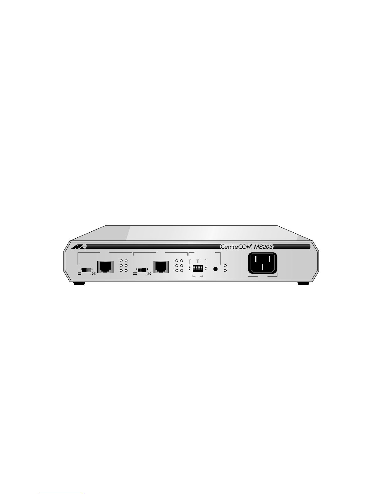
switch’s components are located on the front panel.
Figure 1:
AT-MS203 Micro Switch
1212
1
2
3
6
1
2
3
6
1
2
3
6
1
2
3
6
MDI MDI-X 1
2
3
6
1
2
3
6
1
2
3
6
1
2
3
6
MDI MDI-X
10Base-T/100Base-TX 10Base-T/100Base-TX
TX
RX
COL
LINK
100
FD
TX
RX
COL
LINK
100
FD
FORWARD
POWER
RESET
10
100
Half
Full
DUPLEX
MODE
SPEED
(Mbps)
PORT
PORT 1 PORT 2 CONFIGURATION
SWITCH
POWER
IEEE 802.3/802.3u
Micro Switch

Product Description
2
Note
For definitions of technical terms associated with Allied Telesyn’s
products, refer to the Glossary on Allied Telesyn’s website at
www.alliedtelesyn.com.
Features
AT-MS203 Micro Switch has the following major features:
❑
Two shielded RJ45 10BaseT/100Base-TX ports for Ethernet/Fast
Ethernet connectivity
❑
MDI/MDI-X crossover slide switch for each port
❑
Configuration switch for selecting operating speed (10/100 Mbps) and
duplex modes (Half/Full) for each port
❑
Port and switch status LEDs
❑
Reset button
❑
Internal AC universal power supply with detachable cord
❑
UTP cabling (Category 5; 100Mbps, Category 3-5; 10Mbps)
❑
Up to 100 meters maximum for each end station connection
❑
Full compatibility with other Allied Telesyn 10/100 Mbps products

AT-MS203 Micro Switch Installation Guide
3
Figure 2 shows a typical configuration using the AT-MS203 Micro Switch to
connecttwoEthernet segmentsorcollision domains.Theswitch performsbasic
packet filtering functions and only forwards appropriate packets.
Figure 2:
AT-MS203 Micro Switch Typical Configuration
Server
PORT 1 PORT 2 CONFIGURATION
SWITCH
POWER
Server
Hub Stack
10Mbps 100Mbps
AT-MS203 Micro Switch
Product Description
4
Switch Performance
The AT-MS203 Micro Switch performs at:
❑
148,800 pps for 100 Mbps and 14, 880 pps for 10 Mbps for full wire
speed forwarding and filtering
❑
200 Mbps maximum throughput in 100 Mbps, full duplex mode
❑
20 Mbps maximum throughput in 10Mbps, full duplex mode
❑
Up to 8,192 unicast MAC addresses and unlimited multicast/
broadcast addresses
❑
280K bytes (per port) packet buffer
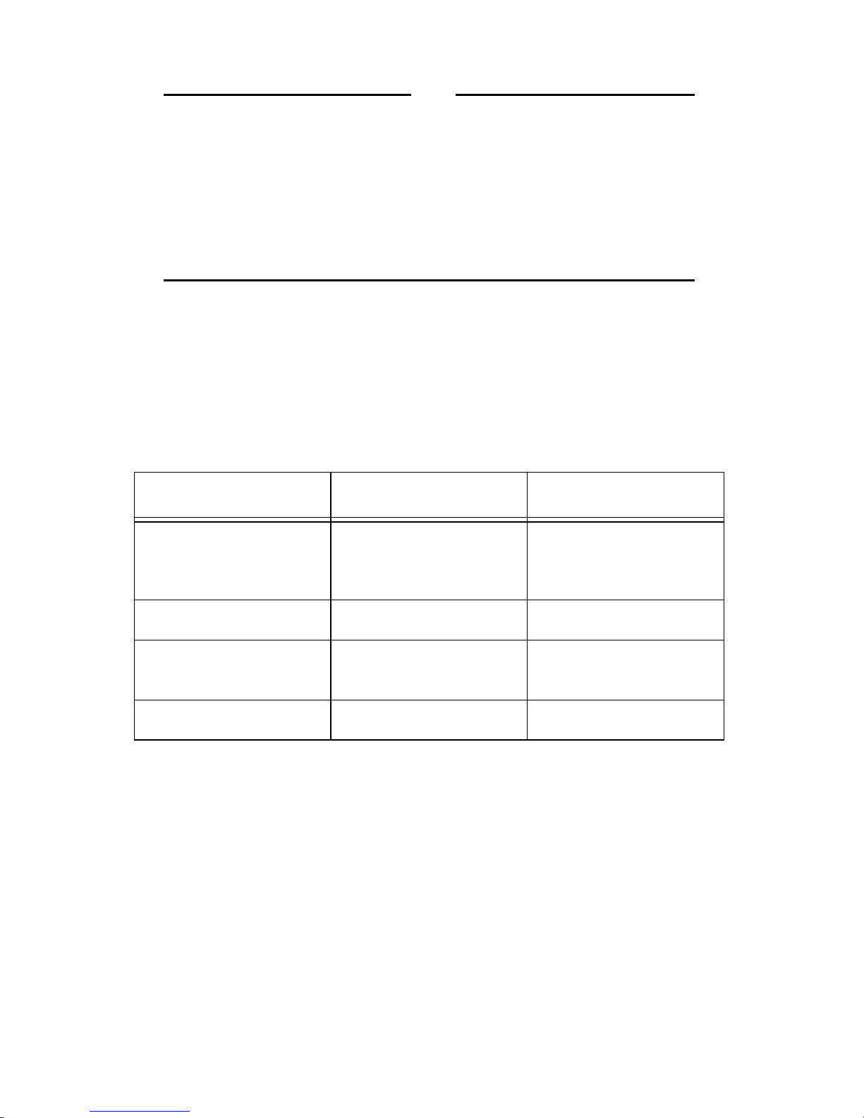
Physical Description
The front panel of the AT-MS203 Micro Switch is equipped with the following
connectors, switches, and LEDs, as shown in Figure 3.
Figure 3:
AT-MS203 Micro Switch Front Panel
UTP RJ45 Connectors
There are two UTP RJ45 connectors, designated as Ports 1 and 2. Both ports
have 10BaseT/100BaseTX connectors each with an MDI/MDI-X switch and can
operate in full or half duplex mode.
MDI/MDI-X Crossover Switch
Each of the two ports has an MDI/MDI-X crossover slide switch. The MDI/MDI-
X slide switch allows you to connect to another bridge, switch or hub for
network expansion, using straight-through cable; therefore, eliminating the
need for a cross-over cable.
1212
1
2
3
6
1
2
3
6
1
2
3
6
1
2
3
6
MDI MDI-X 1
2
3
6
1
2
3
6
1
2
3
6
1
2
3
6
MDI MDI-X
10Base-T/100Base-TX 10Base-T/100Base-TX
TX
RX
COL
LINK
100
FD
TX
RX
COL
LINK
100
FD
FORWARD
POWER
RESET
10
100
Half
Full
DUPLEX
MODE
SPEED
(Mbps)
PORT
PORT 1 PORT 2 CONFIGURATION
SWITCH
POWER
IEEE 802.3/802.3u
Micro Switch

AT-MS203 Micro Switch Installation Guide
5
LEDs
Table 1 lists and defines the individual port and system status LEDs.
Table 1:
Port and System LEDs
LED Color Description
TX Green
ON
indicates that the switch is transmitting signals.
RX Green
ON
indicates that the switch is receiving signals.
COL Yellow
ON
indicates data collisions.
LINK Green
ON
indicates that the link connection is established.
FD Yellow
ON
for FULL Duplex mode indicates simultaneous
(two-way), independent transmission.
OFF
for HALF Duplex mode indicates transmission in only
one direction at a time. Both devices contend for the right
to send data when active transmission is not occurring.
100 Green
ON
indicates the operating speed is 100 Mbps
OFF
means 10 Mbps.
FORWARD
(switch) Green
ON
indicates that the LAN switch is forwarding a packet
from one port of a switch to the other.
POWER
(switch) Green
ON
indicates that the switch is powered on.

Product Description
6
Configuration Switch
The AT-MS203 Micro Switch provides an externally accessible Configuration
Switch to select operating speed (10Mbps or 100Mbps) and duplex mode (half
or full), making it suitable for switching between 10 and 10, 10 and 100, or 100
and 100 Mbps networks, as needed.
Usethe Configuration(DIP)switch tomanuallyconfigurethespeedandduplex
mode for each port. The DIP switch should be set as shown in the following:
Full Duplex Configuration
Configure only one port on the AT-MS203 to full duplex when connecting to a
single workstation or to another switch. Since AT-MS203 does not have auto-
negotiation, also make sure to configure the device at the other end to full
duplex or else you may see transmission difficulties.
Whenconnecting toa hubor repeater,you mustsettheporttohalfduplexsince
this is a shared Ethernet Carrier-Sense Multiple Access with Collision
Detection (CSMA/CD) environment because when set to full duplex, collision
detection is disabled.
RESET Button
Youmust pressthe RESETbuttonanytimeyou changethe configurationof the
switch. For example, when you change the operating speed from 10 to 100, you
must reset the switch to load the new parameters. The RESET also clears all
receive buffers, MAC address tables and restarts the self-address learning
mechanism. Powering the unit off and on is equivalent to the RESET button.
AC Power Connector
AT-MS203 Micro Switch has an internal AC universal power supply rated at
100 to 240 VAC, 50/60 Hz. Allied Telesyn provides different power cords based
on the requirements of different countries.
DUPLEX MODE SPEED (Mbps)
Up = Half Duplex Up = 10 Mbps
Down = Full Duplex Down = 100 Mbps

AT-MS203 Micro Switch Installation Guide
7
A 100-120 VAC power cord (Americas only) supplies the power for all the
internal electronics and LED.The power cord is detachable. Maximum power
consumption for the switch is 10W.
Functional Description
The AT-MS203 Micro Switch supports the following packet transmission
processes:
❑
Frame Processing
❑
Address Recognition and Filtering
Frame Processing
The switch supports store and forward switching at Fast Ethernet full-wire
speed either in 10 or 100 Mbps, half or full duplex mode. Packets entering each
port are stored in buffers. After a complete packet is received, it is forwarded or
discarded appropriately depending on its destination address and error status.
Thisensuresthat onlyerror-freedata packets destinedto another segmentwill
be transferred across the switch, reducing network load. For example, if the
packet entering from Port 1 is destined to an end station on Port 2, it will be
forwarded if its Frame Check Sequence (FCS) is valid. If the packet from Port
1 is destined to an end station also attached to Port 1, then the packet is
discarded.
The switch will discard Cyclical Redundancy Check (CRC) errors, misaligned
packets, runts, and oversized packets. When the packet has dribble bits at the
end, the switch will truncate to octet boundary and check for good FCS before
forwarding.
Address Recognition and Filtering
Upto8,192 MACaddressescan be storedin the MACaddress table. Theswitch
learns all new addresses in real-time after power-up with its address self-
learning mechanism. If the source address of an incoming packet is not found
in the address table, the switch waits until the end of the packet to check for
good CRC and then updates its MAC address table. The switch forwards
multicast and broadcast packets and unicast packets when the MAC addresses
table size is exceeded.


9
Chapter 2
Installation and Troubleshooting
Verifying Package Contents
Make sure the package includes all of the required parts, including:
❑
AT-MS203 Fast Ethernet Micro Switch
❑
Power cord (for Americas only)
❑
Warranty card
❑
This installation guide
Note
If any of the above items are missing or damaged, notify your Allied
Telesyn sales representative.
Ventilation
The AT-MS203 Micro Switch has an internal cooling fan and openings on both
sides for ventilation.
Note
Make sure the ventilation openings on the unit are not blocked.
Maximumambientoperatingtemperatureis122
°
F(50
°
C).Maximum
ambient storage temperature is from 14
°
F to 158
°
F (-10
°
C to 70
°
C).
Installation and Troubleshooting
10
Note
Electrostatic Discharge Precautions.
Static electricity can
damage electronic components of a computer or optional equipment.
To prevent electrostatic damage, observe the following precautions:
Avoid hand contact by transporting and storing products in static-safe
containers. Keep electro-sensitive parts in their containers until they
arrive at a static-free work place. Place parts on a grounded surface
before removing them from their containers. Avoid touching pins,
leads, or circuitry and always be properly grounded when touching a
static-sensitive component or assembly.
Cable Specifications and Requirements
Table 2 provides an overview of IEEE 802.3 and 802.3u cabling specifications
for 10Base-T and 100Base-TX network configurations using twisted-pair cable.
Table 2:
IEEE 802.3 and 802.3u Cabling Specifications
10Base-T 100Base-TX
Media Unshielded/Shielded
Twisted Pair Category 3, 4,
or 5
Unshielded/Shielded
Twisted Pair Category 5
only
Topology Star, Tree Star, Tree
External Devices Network Adapter Card
Repeater Network Adapter Card
Repeater
Maximum Segment Length 100 meters (328 feet) 100 meters (328 feet)

AT-MS203 Micro Switch Installation Guide
11
Installation
In a standalone configuration, the switch supports a maximum of 8,192 MAC
addresses.
To install the switch, do the following:
1. Remove all equipment from the packaging box and store the box and
packaging materials in a safe place.
2. Attach the power cord.
3. Make sure that the green POWER LED is lit.
4. Plug the two 10/100Base-T RJ45 end station cables into the RJ45 ports 1
and 2.
Setting the MDI/MDI-X Switch
1. If you are making a direct connection to workstations using straight-
through cable, set the MDI/MDI-X switch to the MDI-X. position. (MDI-X
is the default position.)
If you are connecting the switch to a hub or to another switch with a
straight-through cable, set the MDI/MDI-X switch to the MDI position.
Figure 4:
MDI/MDI-X Switch Settings
Setting the DIP switch for Speed and Duplex Mode
1. Using the DIP switch, set the SPEED and DUPLEX modes for Port 1 and
Port 2 (UTP ports). The default for both ports is 100Base-TX, half duplex.
The operating speed for each UTP port is shown as follows:
Up = 10Mbps (10Base-T)
Down = 100 Mbps (100Base-TX)
2. Set the DUPLEX mode for Port 1 and Port 2, as shown in the following:
Up = Half Duplex
Down = Full Duplex
3. Verify that the DIP switches are set to the desired configuration.
HUB (MDI-X)NIC (MDI)
MDI-X MDI

Installation and Troubleshooting
12
4. Press the RESET button to load your new configuration.
Note
Every time you change a DIP switch setting, make sure you press the
RESET button to load the new configuration.
5. Connect the opposite end of each cable into a network node or workstation.
6. Verify that the LEDs indicate the correct configuration.
You are now ready to operate your AT-MS203 Micro Switch in a network
configuration. The switch supports a maximum of 8,192 MAC addresses in the
forwarding table.
Troubleshooting Techniques
Followthesetroubleshooting techniques totest for avalidconnection as wellas
to confirm the correct operation of the network.
Connectivity Testing
1. Connect each port to a node or workstation. Then connect the power cord.
2. Make sure that the LINK LEDs for Port 1 and Port 2 are lit.
Note
When testing Port 1 or Port 2, connect the port to a computer and set
the MDI/MDI-X switch to the MDI-X position.
If the LINK LED does not light:
❑
Change the MDI/MDI-X switch setting and make sure that the speed
selection matches the device attached to the other end.
Is the unit receiving power?
Make sure that the POWER LED is lit.
If the POWER LED is not on, check both ends of the AC power cord. Make sure
the power cord is plugged into a functioning wall outlet and that it is properly
inserted into the AT-MS203 Micro Switch power connector.

AT-MS203 Micro Switch Installation Guide
13
Is the LINK LED lit?
The LINK LED lights when a proper connection between the corresponding
10Base-T/100Base-TX port and the equipment connected to it is established. If
this LED is not lit, check for the problems listed as follows and make
corrections as necessary.
1. Problem 1:
The cable has been cut, damaged, or is the wrong cable type.
❑
Solution 1:
— Try making the connection with a different cable. Be sure you are
using an undamaged cable of the correct type.
2. Problem 2:
Connected equipment is not turned on or is not operating properly.
❑Solution 2:
— Check the connected equipment (computer, another switch, etc.)
and turn on the power.
— Make sure that the SPEED and DUPLEX MODE for each port of
the switch match the settings of the attached computer or
additional switch.
3. Problem 3:
The MDI/MDI-X slide switch is on the wrong setting.
❑Solution 3:
— Make sure you use only a straight-through cable, reposition the
MDI/MDI-X switch, and check that the LINK LED is lit.
4. Problem 4:
There is signal loss between the switch and one of the attached network
nodes.
❑Solution 4:
— Make sure the distance between the switch and the connected
network device does not exceed 100 meters.
— Make sure you are using Category 5 cable when operating at 100
Mbps.


15
Appendix A
AT-MS203 Micro Switch Specifications
Physical Specifications
Dimensions: 10.5"L x 7.0"W x 1.75"H
Operating temperatures: 0°to 50°C
Storage temperatures: -20°to 80°C
Relative humidity: 5% to 80% (non-condensing)
Operating altitude: Up to 10,000 ft.
Electrical and Mechanical Specifications
Standard: IEEE 802.3 10Base-T
IEEE 802.3u,100Base-TX
Network Ports: 10Base-T/100Base-TX ports with shielded
RJ45 connectors
Immunity: Conforms to EN500082-1 immunity
standard
Safety: Conforms to all standards normally
supported by ATI products including safety
standards UL 1950, CSA 22.2 No. 950, TUV
and EN60950
EMI/FRI: Meets all applicable requirements for
emissions including but not limited to FCC
Class A, CSA, EN55022 Class A, and CE is
Class B.

AT-MS203 Micro Switch Specifications
16
Cabling Specifications
Table 3 lists the AT-MS203 Micro Switch cabling specifications.
Product Models
Different models of the AT-MS203 Micro Switch are available, depending on
voltage and power cords. Table 4 details the model types.
Jack Connector
Figure 5 shows the switch’s 10Base-T/100Base-TX jack connector which is
located on the front panel.
Figure 5: AT-MS203 Micro Bridge Jack Connector
Table 3: Cabling Specifications
Type STP/UTP Category 3, 4, 5 wiring, 100 ohm impedance at 10Mbps
STP/UTP Category 5 wiring, 100 ohm impedance at 100 Mbps
Length 100 meters between switch and other network nodes
Power internal universal power adapter supplying 100 to 240 VAC, 50/60 Hz
Table 4: AT-MS203 Models
Model Number Voltage/Power Cord Requirement
AT-MS203-10A 100-120 VAC; power cord for U.S.
AT-MS203-20A 200-240 VAC (power cord not available)
AT-MS203-90A 100-120 VAC; power cord for U.S. “Federal”
Pin 1 Pin 8
Table of contents
Popular Switch manuals by other brands


EUCHNER
EUCHNER CTM-C2-BP operating instructions

Brocade Communications Systems
Brocade Communications Systems SilkWorm 2100 Reference

ATEN
ATEN VM5404H user manual

Northern Telecom
Northern Telecom DMS-100 Series General description, installation and maintenance

schmersal
schmersal TQ200 operating instructions

Alcatel-Lucent
Alcatel-Lucent 1850 Installation and System Turn-Up Guide