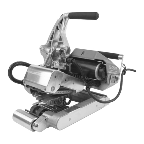
Allied LEISTER WELDPLAST S2 User manual

WELDPLAST
S2
S2-PVC
S2-TPO

Leister WELDPLAST S2 / S2-PVC / S2-TPO
Hand Extruder
Application
Extrusion welding of the following materials:
WELDPLAST S2 PP / PE-HD / PE-LD
WELDPLAST S2-PVC PP / PE-HD / PE-LD / PVC-U
WELDPLAST S2-TPO PP / PE-HD / PE-LD / TPO
Other materials on enquiry
The hand extruder corresponds to the DVS standard 2207–4.
DVS: Deutscher Verband für Schweisstechnik (German Association for Welding Technology)
Read the operating instructions carefully before starting
the device and keep them for future reference.
Operating Instructions (Translation of the original operating instructions)
Warning
Hazardous voltage, danger to life
There is a danger to life from electric shock due to electrical voltage. The extruder must therefore only be
connected to sockets and extension cables with a protective earth conductor. Protect the extruder from mois-
ture and wet conditions. Before starting the device, check the power cord, the plug and the extension cable
for electrical and mechanical damage. The extruder may only be opened by instructed, qualified personnel.
Danger of fire and explosion if the hand extruder is used incorrectly (e.g. overheating of material),
particularly near combustible materials and explosive gases.
Danger – can cause burns! Do not touch bare metal parts and emerging material while hot. Allow
the device to cool. Do not direct stream of hot air or emerging material towards people or animals.
Caution
The nominal voltage indicated on the device must correspond to the mains voltage. If power failure
occurs, the main switch and drive must be switched o (release locking device).
When using the device on building sites, a residual current circuit breaker is essential for the safety
of persons there.
The device must not be left unattended when in use. Heat can reach combustible materials which are
out of sight.
The device may only be used by trained personnel or under their supervision. Children may not
use the device under any circumstances.
120
230
FI
EN

Conformity
EU Declaration of Conformity
Leister Technologies AG, Galileo-Strasse 10, 6056 Kaegiswil, Switzerland confirms that this product in the
version put into circulation by us, fulfils the requirements of the following EU directives.
Directives: 2006/42/EC, 2014/30/EU, 2011/65/EU
Harmonised standards: EN ISO 12100, EN 55014-1, EN 55014-2, EN 61000-6-2, EN 61000-3-2,
EN 61000-3-3, EN 62233, EN 60335-1, EN 60335-2-45, EN IEC 63000
Kaegiswil, 04/15/2021
Bruno von Wyl, CTO Christoph Baumgartner, GM
UK Declaration of Conformity
Leister Technologies AG, Galileo-Strasse 10, 6056 Kaegiswil, Switzerland confirms that this product in the
version put into circulation by us, fulfils the requirements of the following UK Statutory Instruments.
UK Statutory 2008 No. 1597, 2016 No. 1091, 2012 No. 3032
Instruments:
Harmonised standards: EN ISO 12100, EN 55014-1, EN 55014-2, EN 61000-6-2, EN 61000-3-2,
EN 61000-3-3, EN 62233, EN 60335-1, EN 60335-2-45, EN IEC 63000
Kaegiswil, 03/31/2021
Bruno von Wyl, CTO Christoph Baumgartner, GM
Disposal
Do not dispose of electrical equipment with household refuse.
Electrical appliances, accessories and packaging should be recycled in an environmentally friendly
manner. When you are disposing of our products, please observe the national and local regulations.
Technical Data
Voltage V~ 230 200
Power consumption W 3000 2400
Frequency Hz 50/60
Air volume (20°C) l/min 300
Air temperature °C max. 350
Plasticizing temperature °C max. 260
Output (Ø 3 mm) kg/h PE 0.6–1.3 PP 0.5 –1.2 *PVC-U 0.9–1.7 (average values at 50 Hz)
Output (Ø 4 mm) kg/h PE 1.0–2.0 PP 0.9–2.0 *PVC-U 1.5–2.7 (average values at 50 Hz)
Filler rod mm Ø 3 / Ø 4
Vibration acceleration ah (m/s2) < 2.5 (K = 1.5 m/s2)
Dimensions L × B × H mm 450 × 98 × 260 (without welding shoe)
Weight kg 5.8 (without power cable)
Conformity mark
Protection class I
* WELDPLAST S2-PVC The right to make technical changes is reserved

Device Description
1Main switch
2On/o switch for drive
3Potentiometer
4Drive locking device
5Display
6Guide handle
7Jacket heating
8Welding shoe
9Pre-heating nozzle
Operating unit
17 Welding program
18 Actual value - plastic
19 Ideal value - plastic
20 Actual value - air
21 Ideal value - air
22 Drive display bars
23 Output display
24 Menu key
25 Back key
26 Standby/Enter key
27 Down key
28 Select key
29 Up key
30 Drive status display
31 Cursor
With external air duct
24
27 28 29
30
31
17
18
19
20
21
22
23
25 26
With integrated air duct
10 Pipe clip
11 Protection tube
12 Filler rod insertion point
13 Device grip
14 Power supply cord
15 Heating element protection tube
16 Hot air blower (brushless)
44 External hot air duct
9
44
1
12
16
9
10
3
2
13
511
14
78
6
15
4

Work environment/Safety
When not welding, the drive should
be switched o with the drive on/o
switch (2).
Place the hand extruder with corre-
spondingly set and firmly tightened
handle on a stable, fireproof base as
shown in the illustration.
The hand extruder must not be used in areas where there is danger of explosion or flammable
materials. Ensure a safe posture during work. The power cable and filler rod must be free to move
and must not obstruct the user or third parties during work.
Place hand extruder on a fire resistant base. Hot metal parts and hot streams of air must be kept
at a safe distance from the base and walls.
1. Loosen clamp by turning the
guide handle (6) anti-clockwise
2. Move the guide handle (6) into
the desired operating position
3. Tighten clamp again by turning
guide handle (6) clockwise
Leister provides a universal stand
for commissioning and holding the
hand extruder.
Setting the guide handle Workplace
Ensure the minimum cross-section when using extension cables:
The extension cable must be approved for the site of use (e.g. in
the open air) and marked correspondingly.
When using a power unit for power supply, its nominal power
rating is: 2 ×nominal power rating of the hand extruder.
Length
[m]
Minimum cross-section
(at 230V~) [mm2]
Up to 19
2.5
20 – 50 4.0
Extension cables
1
2
3
6

Software and menu guide
The hand extruder Weldplast S2 is provided with a convenient user software, making work easier for the user. Tap
lightly on the keys to operate them.
Workspace functions Menu selection functions
Menu selection Menu selection / Back to workspace
Set contrast Back to workspace (changes not saved!)
Heating on/o Select and back to workspace
Change cursor position Select
Selected value [+] Cursor up / Selected value [+]
Selected value [–] Cursor down / Selected value [–]
The device heats up to the last ideal temperature set directly after switching on the main switch (1). When
the ideal temperature is reached, a counter on the status display counts back from 220 seconds to zero. After
this start-up process is complete, the device is ready to weld (status Ready*). The hand extruder takes around 6
minutes to reach its temperature range.
If the power is only turned o for a short time, the start-up process does not need to be repeated.
Motor disabled
Start-up waiting period: 220 seconds
Heating M free Ready*
Drive status
display (30)
Heating until ideal
values are reached Motor release Ready to weld
The temperature control prevents the hand extruder from being started while it is cold.
Welding preparation
Start window
After turning on the hand extruder
with the main switch (1), the device
name and current software version
will be displayed for 3 seconds.
Workspace
The workspace shows the
parameters which are
currently set.
Setting the parameters in the workspace
The cursor (31) shows which parameters can be
set. After the device is switched on, the cursor
is situated on «SPEED». «AIR» or «PLAST» can
be selected with the Select key (28) and their
values can be changed using the Up key (29) or
Down key (27).Set value Set value Set value

Monitoring the welding parameters
The actual and ideal values of the AIR and PLAST temperatures are constantly monitored. If an actual value deviates
from the relevant ideal value (value is outside the range of tolerance), this will be indicated by a change in status
on the status display (30). If necessary, the drive motor will be temporarily disabled until the welding parameters
are back in the specified tolerance range. The possible status display and the ranges of tolerance are shown
in the following graphic and table.
No Status display Status characteristics
Ready* Ready to weld
M free Divergence from welding parameters (plastic) > 10°C
Heating
Divergence from welding parameters (plastic) > – 30°C, drive motor disabled
30s Start-up waiting period of 30 sec., drive motor disabled
Too hot
Divergence from welding parameters > + 30°C, drive motor disabled
Setting the output volume
The output volume and the pre-heating time can be coordinated with
each other according to the type of seam.
• Presetting on the display
– Move the cursor to the «SPEED» position by pressing the Select key
(28).
– Specify the maximum output value (30-100 %) using the Up (29)
or Down (27) keys (displayed on the drive display bars (22)).
• Precise adjustment during the welding process
– The output volume can be reduced from the maximum set value
(e.g. 85%) to the minimum by turning the potentiometer (3).
The output volume is dependent on the size of filler rod used. If the output
is too large when the output display is set to «30» and the potentiometer
to «Minimum», the filler rod must be changed to the next size down.
Setting the PLAST and AIR temperatures
• Move the cursor to the «PLAST» or «AIR» position by
pressing the Select key (28).
• Set the temperature value by using the Up (29) or
Down (27) key.
3
22
Example
Welding preparation
24
27 28 29
30
31
17
18
19
20
21
22
23
25 26
Temperature display
Reference value
Actual value
Displayed state
Time
Motor
enabled Motor
ena. Motor
enabled
1
2
3
4
5

Starting the welding process
• Fit the appropriate welding shoe (8) according to requirements.
• Set potentiometer (3) to max.
• When the operating temperature has been reached (Status Ready*), welding can begin.
• Press on/o switch for the drive (2).
• Feed filler rod with a diameter of 3 or 4 mm into the filler rod insertion point (12).
• The filler rod will be automatically pulled through the filler rod insertion point (12). The rod feed must take place
without resistance.
WARNING!
Always operate device with filler rod, but never feed filler rod into both filler rod insertion points
at the same time.
• Pause the delivery of material with the on/o switch for the drive (2).
• Direct the pre-heating nozzle (9) onto the area to be welded.
• Warm the area to be welded with oscillating movements.
• Attach the device to the prepared welding area and press the drive on/o switch (2) again.
•Carry out a test weld according to the welding instruction of the material manufacturer and national stan-
dards or guidelines.
• Check the test weld.
•
Adjust temperature settings and output amount according to requirements.
•
During a longer period of welding, the on/o switch for the drive (2) can be kept in continuous ope-
ration using the drive locking device (4).
• PVC-U may only be processed in the PVC-U menu. WARNING: Only use PVC-U (not PVC-C).
•
To prevent corrosion, if the machine is not going to be used for a longer period of time (more than 2 days) it is
recommended to fill it with HD-PE.
WELDPLAST S2 - PVC

Menu
Select program
Selection
Enter
Programs 1-3 are provided with preset parameters which can be adjusted during the welding process.
The adjustments are not saved!
The free settings 1-4 are preset in the factory and can be programmed freely. The parameters are saved even
after the device has been switched o.
Setting the output volume
• Move the cursor to the «SPEED» position by pressing the Select key (28).
• Set the output value (30-100 %) by using the Up (29) or Down (27) key.
Setting the PLAST and AIR temperature
• Move the cursor to the «PLAST» or «AIR» position by pressing the Select key (28).
• Set the temperature value by using the Up (29) or Down (27) key.
The welding program (17) which is currently set can be seen in the workspace.
The display of the materials may vary according to the machine and software versions.
Free
setting
1-4
Welding program Ideal PLAST [°C] Ideal AIR [°C]
Free set 1 – 4 230 260
Prg1 PE-LD 220 260
Prg2 PE-HD 230 260
Prg3 PP 240 260
Prg0 PVC-U 200 300
Program: the display of the materials may vary according
to the machine and software versions.
Welding parameters
• Release drive locking device (4) and let go of the on/o switch for the drive (2)
Remove welding material in the welding shoe, so that the welding shoe will not be damaged the next time the
device is started up.
• Turn off the heating with the Standby/Enter key (26).
• Allow device to cool down for approx. 5 minutes.
• Turn o main switch (1).
Turning the device o

Contrast setting
In unfavourable lighting conditions and with
ambient temperature fluctuations, the contrast
can be set by using the Back key (25)
.
Heating ON/OFF
During a longer period on standby, the heating for
PLAST and AIR can be switched o using the Standby/
Enter key (26)
.
Menu
Menu
Selection
Select
Functions
Selection
Select
and Back
Back to
workspace
selection
Activate key lock
1. Menu
2. Key lock
3. Activating
If the keypad is locked, ‘key lock’ will appear
in the display.
The lock is released as follows:
Deactivate key lock
1. Back
2. Reset
3. Select
The reset must be confirmed by pressing the
Select key immediately!
Key lock
activated
Additional settings Menu guide
Activate
Standby

If the drive of the extruder is switched o and no key input is made for a certain time, the cool down mode starts
automatically after the standby time has elapsed.
Setting the standby time
This menu is used to activate and set the standby time.
Press the key to switch standby on or o.
Press the and keys to set the time from 5-120 minutes.
The factory setting is 40 minutes.
Press the key to return to Work mode.
The cooling process is initiated.
If any key is pressed before the countdown has elapsed in standby mode (180 seconds),
the display returns to the initial state.
If no key is pressed during the countdown, the cool down mode starts. Pressing any key
heats up the extruder again and the work display switches to Work mode.
Standby

If an error occurs, this will be shown in the status display (30) (e.g. Err04 Motor overheated).
Display ErrXX
If an error occurs, the heating for AIR and PLAST and the drive motor will be switched o immediately.
If this does not happen, the device should be disconnected from the power supply immediately!.
How to proceed with the status display of the drive (30) ErrXX
•Note error code.
•Release drive locking device (4) and let go of the on/o switch for the drive (2).
•Turn o main switch (1).
•Operate the device again, monitoring it carefully, and make sure that the hand extruder is not being overheated
from external sources.
•If possible, expel the plastic remaining in the screw.
•If the error occurs again, the device should be sent to the service point for inspection, with a note of the
error code.
Error messages
Overheating protection for the drive
If the drive is overheated by external influences or a PLAST temperature which is too low, the internal protection
against excessive temperatures will turn the drive o (see Err04 ).
Accidental start-up protection for the drive
The drive motor is protected against accidental start-up after errors, e.g. overheating Err04 . The message «Switch
o drive» appears in the display (5) while the drive motor is disabled. After correcting the error and switching o
the drive (release drive locking device (4) and let go of the on/o switch for the drive (2)), the message «Switch
o drive» will disappear in the Display (5). Welding may continue.
The following errors are recognised by the device:
Display Type of error
Err01 Air temperature too high or defective temperature sensor
Err02 Plastic temperature too high or defective temperature sensor
Err04 Engine coil temperature too high, motor has overheated
Err08 Heating element AIR temperature too high or blower motor has failed
Err10 Electronics temperature too high
Err40 Short circuit in PLAST temperature sensor
If several errors occur simultaneously, e.g. Err02 and Err04 , Err06 will be displayed.
Further combinations are shown with the letters A, B, C, D, E and F, e.g. Err08 and Err02 Display Err0A .

Disassembly
– Turn off the device while warm and disconnect from the power supply.
– Remove the welding shoe (8) with the welding shoe holder (34) by unfastening the clamp screws (35) from
the extruder nozzle (32).
– Every time the welding shoe is changed, clean the extruder nozzle (32) of welding residue and make sure that
it is screwed in tightly.
– Remove welding shoe (8) from the welding shoe holder (34) by unfastening the fastening screws (33).
Assembly
–Fasten a welding shoe (8), appropriate to the welding seam, onto the welding shoe holder (34) with
fastening screws (33).
– The welding shoe (8) and welding shoe holder (34) must be tightened properly with the clamp screws (35).
Danger – can cause burns! Only work with heat-resistant gloves.
The welding shoe must be changed while the device is still warm from operation.
8Welding shoe
32 Extruder nozzle
33 Fastening screw
34 Welding shoe holder
35 Clamp screw
The welding shoe (8) can be turned infinitely to the
desired welding direction by loosening the clamp
screws (35).
The clamp screws (35) must be tightened well again
afterwards.
Replacing accessories
To disassemble the hot air duct (44), first remove the welding shoe (8). After loosening
the locked fastening screw (45) on the pipe clip (10) and the clamp screw (47) on
the hot air duct connector, the entire unit can be pulled out.
Assembly in reverse order
.
Changing the hot air duct
888
8
44
4510
47
35
8
8
33
32
34
35
35
Welding direction
Changing the welding shoe

Disassembly: For the pre-heating nozzle (9), unscrew clamp screw (43) and pull
pre-heating nozzle (9) o the hot air duct (44).
Assembly: Push pre-heating nozzle (9) onto the hot air duct (44).
Make sure that it is aligned parallel to the nozzle shoe.
Tighten clamp screw (43).
Three dierent pre-heating nozzles (9) corresponding
to the weld seam width are available. The nozzle cross
sections correspond to the DVS guidelines.
Nozzle 1
Seam width
to 15 mm
Nozzle 2
Seam width
16 to 20 mm
Nozzle 3
Seam width
21 to 40 mm
Pre-heating nozzles for extruders with external air duct
Changing the pre-heating nozzle
9
44
43
Leister Technologies AG oers the right welding shoes for all common types of seam in various sizes:
Blank V Seam Fillet
weld
Overlap
seam
Corner
seam
outside
Corner
seam
short
Corner
seam
long
Angled adapter
WELDPLAST S2 / WELDPLAST S2-TPO
with integrated air duct
WELDPLAST S2 / WELDPLAST S2-PVC
with external air duct
Welding shoe range
45°
Blank V Seam Fillet
weld
Overlap
seam
Corner
seam
outside
Corner
seam
short
Corner
seam
long
90°

• Repairs should only be carried out by authorised Leister service points. These guarantee a professional, reliable
repair service within 24 hours, using original replacement parts according to the circuit diagrams and
replacement part lists.
• If a service message with the service code 1 appears after the WELDPLAST S2 is turned on,
the carbon level should be checked by an authorised Leister service point and, if necessary,
the carbon brushes of the drive changed.
• The message can be hidden by pressing the Select key (28) .
• The hand extruder may continue to be operated for a short time.
• If the carbon brushes are not exchanged in good time, the drive will operate until it reaches
the mechanical carbon shut-o point. No error message will appear on the display, but the
drive will no longer operate.
Maintenance
•Check power supply cord (14) and plug for electrical and mechanical damage.
• Clean the extruder nozzle (32) of welding residue every time the welding shoe is changed.
Service and Repairs
Warranty
• For this tool, the guarantee or warranty rights granted by the relevant distributor/seller shall apply. In case of
guarantee or warranty claims any manufacturing or workmanship defects will either be repaired or replaced by the
distributor at its discretion. Warranty or guarantee rights have to be verified by an invoice or a delivery document.
Heating elements shall be excluded from warranty or guarantee.
• Additional guarantee or warranty claims shall be excluded, subject to mandatory provisions of law.
• Warranty or guarantee shall not apply to defects caused by normal wear and tear, overload or improper handling.
• Warranty or guarantee claims will be rejected for tools that have been altered or changed by the purchaser.
Only Leister accessories may be used.
Transportable welding rod de-reeler
• The de-reeler is designed for rolls of welding rod
with Ø 300 mm.
• To ensure that the filler rod is unwound as smoo-
thly as possible, it should be fed through the
specially designed eyes (41).
Stand
Accessories
41

Your authorised Service Centre is:
© Copyright by Leister
Allied Power Tools
12/ 76 Rushdale St, Knoxfield VIC 3180 Australia
T: + 61 3 9764 2911
W: www.alliedpowertools.com.au
This manual suits for next models
2
Table of contents
Other Allied Welding System manuals
Popular Welding System manuals by other brands

Thermal Dynamics
Thermal Dynamics CutMaster 75 operating manual

Miller
Miller XMT 350 FieldPro owner's manual

Stel
Stel TIG dp 181H instruction manual

Zenit Powertools
Zenit Powertools MMA-200/2 instruction manual

Taylor
Taylor SYSTEM CD200 SERIES operating manual

EWM
EWM Pico 300 cel pws vrd 12V operating instructions

PROPOINT
PROPOINT 8619470 operating manual

lamart
lamart PUK D5 operating manual

Lincoln Electric
Lincoln Electric Power-Arc 5500 Operator's manual

Lincoln Electric
Lincoln Electric Power Wave C300 Specifications

Greencut
Greencut SOLDADOR MIG100 instruction manual

ToolPRO
ToolPRO POWER CUT 25K instruction manual