Allied Leister GEOSTAR G5 LQS User manual

2
Table of contents
1. Use 3
1.1 Intended use 3
1.2 Non-intended use 3
2. Important safety instructions 4
3. Technical data 5
4. Transport 5
5. Device description 6
5.1 Overview of device parts 6
5.2 Operating unit 7
5.3 Status LED display “Heating” 7
5.4 Status LED display “Drive” 8
5.5 Operating unit description 8
5.6 Display description 9
5.7 Function and working display 9
6. Menu navigation 14
7. Work environment/Safety 15
7.1 Extension cable 15
7.2 Preparation for welding 15
8. Setting the welding parameters 16
8.1 Function description 19
8.2 Speed and temperature setting before welding 19
8.3 Setting the speed and temperature during welding 20
8.4 Starting the device 21
8.5 Welding process 22
8.6 Switching o the device 22
8.7 Display of day's distance 23
8.8 Deleting the day's distance 24
8.9 Key lock 24
8.10 Recipe selection 24
8.11 Entering names or passwords 25
8.12 Defining recipes 25
9. Power supply interruption 27
10. Adjusting the track roller height 27
11. Change gear speed 28
12. Replacement of pressure rollers 30
13. Welding wedge replacement 31
14. Warnings and error messages 32
15. Accessories 33
16. Training course 33
17. Maintenance 33
18. Service and repair 33
19. Conformity 34
20. Disposal 34

3
Operating instructions (translation of original operating instructions)
Read the operating manual carefully before commissioning
and keep it on hand for later consultation.
We congratulate you on the purchase of a GEOSTAR wedge welder.
You have selected a first-class wedge welder comprised of high-quality materials. This device was developed and
produced in accordance with the latest welding technologies. Every GEOSTAR is subjected to strict quality monitor-
ing before it leaves the factory in Switzerland.
1. Use
For welding materials made of PVC, a device model designed for that purpose with a steel wedge
must be used.
Additional materials upon request
More information about GEOSTAR and myLeister can be found at www.leister.com
GEOSTAR G5 LQS/G5 Material Material thickness reference value
Copper PE-HD, PE-LD, PP, TPO, FPO 0.8 – 3.0 mm
Steel PVC-P 0.8 – 3.0 mm
GEOSTAR G7 LQS/G7 Material Material thickness reference value
Copper PE-HD, PE-LD, PP, TPO, FPO 1.0 – 3.0 mm
Steel PVC-P 1.0 – 3.0 mm
GEOSTAR G5 LQS/G5
GEOSTAR G7 LQS/G7
Wedge welder
The GEOSTAR G5/G7 with and without LQS is designed for overlap welding of thermoplastic films and sealing
sheets. Only use original Leister spare parts and accessories; otherwise, any warranty and/or guarantee claims will
be invalidated.
Welding geometry
• The maximum overlap width of the lower and upper membranes is 150 mm.
• Welding seam widths 50 mm.
• Welding seam with/without test channel (depending on version).
1.1 Intended use
1.2 Non-intended use
Any other use or any use beyond the type of use described is deemed to be a non-intended use.

4
Danger to life
There is a danger to life from electric shock due to electrical voltage. The hot
wedge welding machine must therefore only be connected to sockets and
extension cables with a protective earth conductor. Protect the hot wedge welding
machine from moisture and wet conditions. Before switching on, check the power
cord, the plug, and the extension cable for electrical and mechanical damage.
The hot wedge welding machine may only be opened by instructed, qualified
personnel.
Danger of fire and explosion
The hot wedge welding machine can become an ignition source for fire and
explosion. It must therefore not be used near explosive gases or flammable
materials To avoid burning of the material to be welded, please read the material
safety data sheet from the material manufacturer. The hot wedge welding machi-
ne must only be used in the open or in a well-ventilated area.
2. Important safety instructions
Risk of burning
Do not touch the hot wedge when hot. The device should always first be allowed
to cool down.
Do not touch moving parts
There is a risk of inadvertently becoming caught and being pulled in. Do not wear
loose articles of clothing such as scarves or shawls. Tie up long hair or protect it
by wearing headgear.
If the device is being used on construction sites, a fault current circuit breaker
must be used to protect site personnel.
When welding, be aware of hazards in the surrounding area, e.g., risk of tripping,
risk of slipping, strong sunlight, unattended equipment, etc.
The device may only be operated under supervision as waste heat can reach
flammable materials.
The device should only be operated by trained specialists or under their super-
vision. Children are not permitted to operate the device.
The local supply voltage must match the line voltage specified on the device. If
the line voltage fails, switch o the main switch and place the welding machine
in the park position.
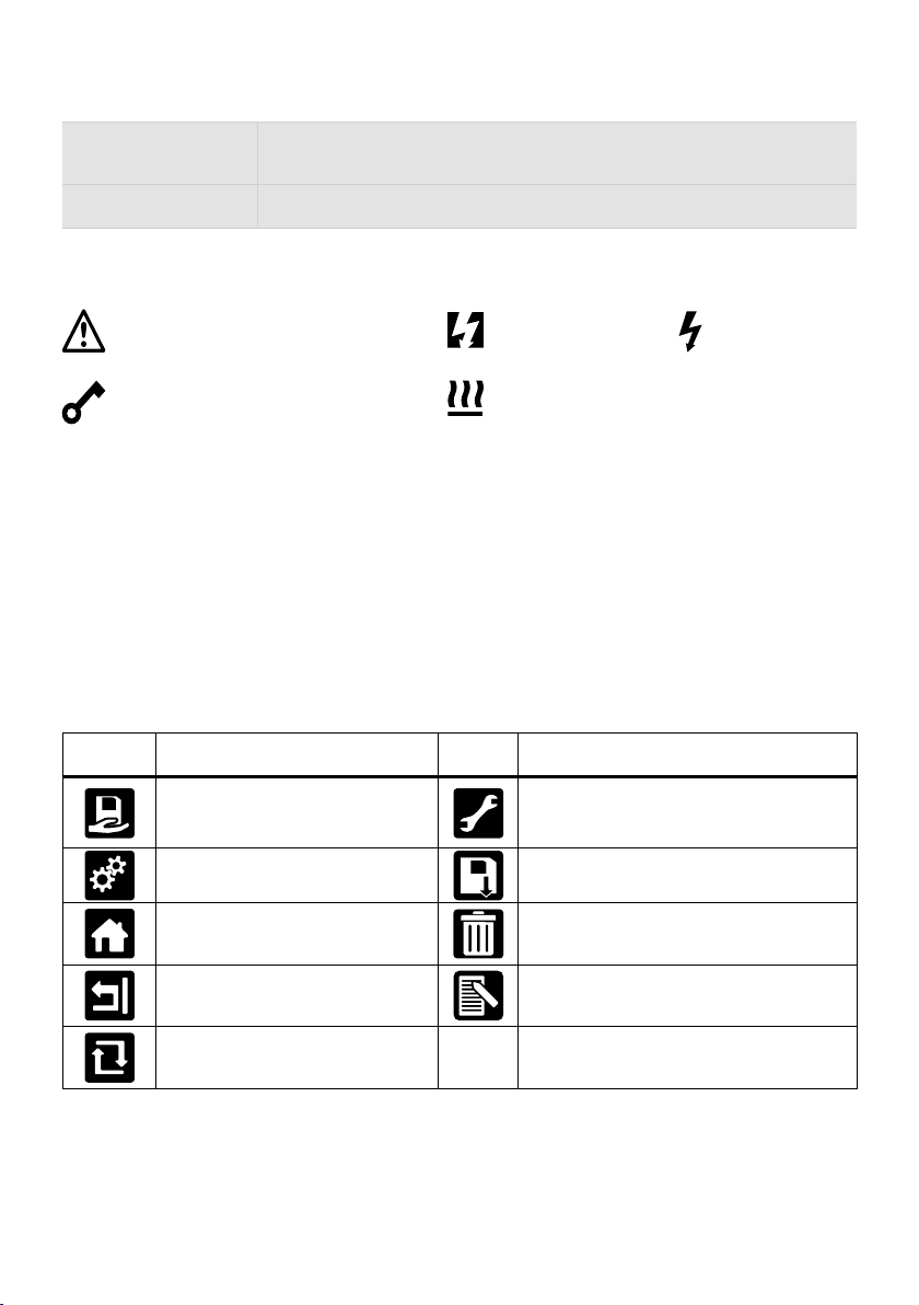
Warning
Caution

5
3. Technical data
Device model GEOSTAR G5 LQS
GEOSTAR G5
GEOSTAR G7 LQS
GEOSTAR G7
* Voltage V~ 220 – 240 220 – 240
Power W 2800 2800
Frequency Hz 50 / 60 50 / 60
Temperature, stepless °C
°F
80 – 460
176 – 788
80 – 460
176 – 788
Drive slow, stepless m/min
ft./min 0.8 – 6
2.6 – 19.6
0.8 – 7
2.6 – 22.9
Drive fast, stepless m/min
ft./min 1.5 – 12
4.9 – 39.3
1.5 – 12
4.9 – 39.3
Welding pressure max. N/lbs 1500 / 337 1500 / 337
Emission level LpA (dB) 60 60
Dimensions (L × W × H) mm 482 × 278 × 269 482 × 278 × 269
Weight (without power cord) kg/lbs 16.4 / 36.2 17.7 / 39
Mark of conformity
Protection class I
Device G5 G7
Welding wedge length mm 90 130
Width of welding wedge mm 50 50
Weld seam width mm 2 × 15
We reserve the right to make technical changes. Additional versions upon request
*Connection voltage cannot be switched
Suitable transport equipment must be
used to transport the machine.
The welding wedge (5) must
be cooled down for transport.
Do not store any flammable
materials in the transport box
4. Transport
Do not use handles on the device or
carrying handles on the transport box for
transport with the crane.
Comply with applicable national regulations regarding the carrying or lifting of loads.

6
16
15
20
19
21
11
3
7
10
9
8
12
6
5
4
1
18
2
22
13
14 15 17
1. Power supply cord
2. Main switch
3. Operating unit
4. Clamping arm
5. Welding wedge
6. Towing bar
7. Clamping lever
8. Welding force adjustment ring
9. Welding force safety bolt
10. Clamping lever lock
11. Handle
12. Track roller, rear
13. Welding wedge plug
14. Contacting system, upper
15. Contacting system, lower
16. Upper drive/pressure roller
17. Lower drive/pressure roller
18. Track roller, front
19. Setting screw, contacting system, lower
20. Locking screw, contacting system, lower
21. Welding wedge locking screw
22. Swivel head
5. Device description
Operating unit (3)
For switching the GEOSTAR wedge welder on/off
«e-Drive»
The «e-Drive» is used as the navigator.
It has two functions:
Rotate to the left or right in order to set
various menus or values.
Press to confirm or to
activate.
Main switch (2)
5.1 Overview of device parts

7
27
35
36
34
3332
28
29
30
31
27. “Up” key
28. “Down” key
29. Key for heating “On/O”
30. Key for drive “On/O”
31. Status LED
32. «e-Drive»
33. Function display
34. Working display
35. Status display “Section 1”
36. Status display “Section 2”
LED status (31)
Heating On/Off (29) Condition Cause
LED off Heating is switched off.
LED flashes green Heating is switched on. Temperature
is outside the tolerance range.
LED continuously green Heating is switched on. Temperature
is within the tolerance range.
If, during operation, a warning message occurs in the Status display area 2 (36) or if there is an error message
in the working display (34), then this will be displayed as followed:
LED flashes red Warning message for the heating See warning and error message.
LED continuously red Error message for the heating See warning and error message.
The LED on the Heating “On/Off” key (29) displays the conditions of the heating.
5.2 Operating unit
5.3 Status LED display “Heating”

8
The LED of the Drive “On/Off” key (30) shows the condition of the drive when it is working as intended.
LED status (31)
Drive On/Off (30) Condition Cause
LED off Drive is switched off.
LED continuously green Drive is switched on.
If, during operation of the drive, a warning message occurs in the Status display area 2 (36) or if there is an
error message in the working display (34), then this will be displayed as follows:
LED flashes red Drive current limiting is active. See warning and error message.
LED continuously red The drive has an error. See warning and error message.
Keyboard mode Current selection
Working display
Current selection
function display
Current selection
Set-up menu
Up (27)
Down (28)
Changes the position
within the working
display.
Switches from
function display to
working display.
Changes the position
within the Setup menu.
Heating
On/Off (29) Switched heating
on/o
Switched heating
on/o No function
Drive
On/Off (30) Switches drive
on/o
Switches drive
on/o No function
Press
«e-Drive»(32)
Set value is adopted
straight away and
the selection jumps
straight back to the
function display.
Selected
function is
executed.
Selection of the marked
position.
Rotate
«e-Drive»(32)
Setting the desired
setpoints in 5 °C or
0.1 m/min increments
Changing the
position in the
Function display.
• Changes the position
within the Setup menu
• Setting the value of the
selected position
5.4 Status LED display “Drive”
5.5 Operating unit description

9
• In the function and working display, it is always the highlighted field/symbol of the current selection that is defined.
Symbol Meaning Symbol Meaning
Select freely definable and predefined
profiles
Service menu
(can only be accessed by entering the password)
Settings Save
Return to working display
(exits a menu directly) Delete the selected item
Go back one level Edit the selected item
Reset settings or hour counter
Function display (33)
Name of the
saved value
Profile currently selected. If profile names consist of more than 6 characters, the first
6 characters are shown first, followed by the remaining characters.
230 V Network voltage currently present on the mains plug.
Undervoltage Overvoltage
Heating
(only with activated heating)
Warning present
(see Chap. Warning & Error Messages)
Key lock
(only with active key lock)
Status display “Section 1” (35)
Status display “Section 2” (36)
5.6 Display description
5.7 Function and working display

10
Symbol Meaning
Drive speed [m/min / ft./min]
Drive speed blocked [m/min / ft./min]
Welding wedge temperature [°C/°F]
Welding force [N/lbf]
Information box
Devices in standby mode. The heating is switched o after the counter runs through.
An error has occurred. An error code also appears
(the device is no longer ready for use). Contact an authorized service center.
See Chapter “Warnings and error messages”
Warning:
See Chapter “Warnings and error messages”
380
160 °C The arrow pointing upward and the progress bar indicate that the setpoint
(shown on the progress bar) has not yet been reached (too cold). The flashing value
is the actual value. The value next to the progress bar is the setpoint.
390 °C
380
The arrow pointing downward and the progress bar indicate that the setpoint
(shown on the progress bar) has not yet been reached (too hot). The flashing value
is the actual value. The value next to the progress bar is the setpoint.
385 °C
380
If “Set Values” is activated, both the actual temperature (large font size) and the set
temperature (small font size) are displayed. Default setting ex-works.
°C
380 If “Set Values” is deactivated, then only the actual values (large) are displayed
during operation, otherwise only the setpoint values (large).
Working display (34)

11
Startup display
Display at the time of start-
up with software release
and device model.
Maintenance service
If the maintenance interval
for the device has been
reached, “Maintenance
Servicing” will appear after
the startup display. The dis-
play disappears automat-
ically after 10 seconds or
can be confirmed by press-
ing «e-Drive» . You must
take the device to your ser-
vice center.
Start display
All setpoint and actual val-
ues are displayed in the
start display. The heating
is not yet switched on. All
setpoint values can be set.
Welding startup display
Display during the heating
process.
Recipe selection
Select a recipe that you
have defined. The process
of selecting a recipe is
described in detail in the
Chapter “Load recipes”.
Setting
In the basic setting, you
can save recipes and ac-
cess the standby function
and transmission ratio via
the “Setup” menu. Select
“Advanced Mode” to ac-
cess a range of other set-
tings options.
Freely definable recipes
The process of saving
freely definable recipes is
described in detail in the
Chapter “Save recipe”.

12
Readiness
Standby mode is activated.
If the engine is switched
o, the heating activated
and if no button is ac-
tivated during the time
defined under “Standby
interval”, then the device
will switch over automati-
cally into Standby display.
If the «e-Drive» is not
pressed during the subse-
quent 180 seconds, then
the heating will shut o au-
tomatically. “Standby” will
then appear afterwards
on the display. Pressing
«e-Drive» causes the
device to switch to Work-
ing mode.
Standby mode is deactivat-
ed in the factory settings.
Gear Ratio Drive
The value (slow/fast) must
match the sprocket wheel
arrangement in the gear-
box. Chapter “Change gear
speed”
Show Duty Info
Hours Drive:
Current running time
of the drive
Hours Heating:
Current running time
of the heater
Hours Machine:
Current running time
of the machine
Day Distance:
Currently traveled distance
(can be reset)
Total Distance:
Total distance traveled.
Show General Info
Firmware HMI:
Software version of
thedisplay unit
(communications module).
Firmware Machine:
Software revision
Production Info:
Information on date
of production and
production number
Warning display
If there is a warning pend-
ing, this is indicated by the
symbol in the status dis-
play. The “Warnings” menu
contains more detailed in-
formation about the current
warning.

13
Set Values
If “Set Values” is activated,
both the actual values and
the set values are displayed
in small font size.
Factory setting activated.
Reset to defaults
If the “Reset to defaults”
menu is selected and
confirmed by selecting the
relevant function, all cus-
tomer-specific profiles will
be deleted. Settings that
have been changed via the
Setup menu will be reset to
the factory settings.
Machine Setup
Unit:
Adjusting the unit used
(metric/imperial)
Unit Speed:
Adjusting the LCD contrast
Unit Heat:
Adjusting the background
illumination of the display
Unit Force:
Adjusting the background
illumination of the key-
board
Application Mode
If “Application Mode”
is activated, then more
detailed information on the
drive and heating capacity
utilization appears in the
working display (34).

14
6. Menu navigation
Available only in “Advanced Mode”
The GEOSTAR G5 LQS and GEOSTAR G7 LQS have the Leister Quality System (LQS) and thus the
function of welding data recording. Using the LQS and myLeister app, the drive speed, the hot-wedge
temperature and the joining force are recorded during welding over the welding seam length at the
specified distance interval. You can find more information in the corresponding operating instructions
LQS/myLeister at www.leister.com/um-geostarg5g7.

15
7. Work environment/Safety
The device should only be used in the open or in a well-ventilated area. Be careful not to burn the material during
welding.
Read and follow the safety precautions provided by the manufacturer for the material.
• The minimum cross-section must be observed when extension
cables are used.
• The extension cable must be authorized for the utilization site
(e.g. outdoors) and be marked accordingly.
• When a power plant is used as an energy supply, the following
applies for its nominal output: 2 × nominal output of the wedge
welder and fitted with FI switch.
• Power plant must be grounded.
• If you are using a mobile power generator, it should have a total distortion fraction of the sine waveform (THD=To-
tal Harmonic Distortion) of less than 6%. This information can be found in the technical data or can be obtained
from the supplier. When using mobile power generators with a THD value greater than 6%, damage to electronic
components may occur. Leister therefore recommends using portable power generators with inverter technology.
The hot wedge welding machine may only be switched on and o when the generator is running, otherwise the
electronic components may be damaged.
• Overlap width max. 150 mm
• Sealing sheets must be clean and dry between the overlaps and on the upper and lower side.
The wedge welder can be placed in three different positions during interruptions in work or for cooling down.
The clamping lever must be locked while doing so.
Prior to commissioning, check the power supply cord (1), the plug, and the extension
cable for electrical and mechanical damage. Use extension cables with protective con-
ductors only.
The wedge welder may not be used in areas with explosion and/or ignition hazards.
Ensure a stable position during work. The power supply cord (1) must be able to move
freely and must not hinder the user or third parties while working.
Place the wedge welder on a horizontal, fireproof support and ensure sufficient distance
from flammable materials and explosive gases!
7.1 Extension cable
7.2 Preparation for welding
230 V~ up to 50 m 3 × 1,5 mm²
up to 100 m 3 × 2,5 mm²
120 V~ up to 50 m 3 × 1,5 mm²
up to 100 m 3 × 2,5 mm²

16
4
19
5
20
10 7
8
9
11
8. Setting the welding parameters
A. Press the locking clamping lever (10) and swing the clamping lever (7) up until the lock engages. Use your
other hand to accomplish this by holding the automatic welder firmly by the handle (11). Unlock the welding
force safety bolt (9) by pulling and rotating 90°. Set the clamping arm (4) to the maximum opening using the
welding force adjustment ring (8).
B. While unclamped, detach the lower contacting system locking screw (20). Screw the lower contacting
system setting screw (19) a sucient distance away from the welding wedge (5) using a 4 mm socket
wrench.
CAUTION!
The welding wedge is set to 2 mm membranes in the factory settings.
The welding wedge (5) must be cooled down for adjustment purposes.
Danger of crushing when closing the clamping arm (4).
Welding force and contacting system
Switch o GEOSTAR with the main switch (2) and disconnect from the mains.

17
14 15
17
16
10
7
8
45
11
2 4
103 7 8
11
C. Insert test strips (lower and upper membranes) of the material to be welded between the upper and lower drive/
pressure rollers (16/17) and between the upper and lower contacting systems (14/15) and welding wedge(5).
Press the locking clamping lever (10) and close the clamping arm (4) using the clamping lever (7).
Use your other hand to accomplish this by holding the automatic welder firmly by the handle (11).Rotate the
welding force adjustment ring (8) until the pressure rollers touch lightly against the material to be welded.
D. Connect the GEOSTAR to the mains and switch on the main switch (2). Press the locking clamping lever (10)
and swing the clamping lever (7) upwards until the locking clamping lever engages (10). Use your other
hand to accomplish this by holding the automatic welder firmly by the handle (11). Rotate the welding force
adjustment ring (8) while open until the welding force on the operating unit (3) matches the desired value
with the clamping arm (4) clamped and the test strip inserted.
CAUTION!
Mechanical damage could occur if the maximum welding force of 1500 N is exceeded.
Do not touch moving parts
There is a risk of inadvertently becoming caught and being pulled in. Do not wear loose articles
of clothing such as scarves or shawls. Tie up long hair or protect it by wearing headgear.

18
14
5
19
15
2
19
20
10
7
11
E. Switch o the main switch (2) and disconnect GEOSTAR from the mains. While clamped, screw the lower
contacting system (15) with the lower contacting system setting screw (19) in the direction of the welding
wedge (5) until the lower test strip is touching the welding wedge (5). Then rotate the lower contacting
system setting screw (19) once in the direction of the welding wedge (5) so that the upper contacting
system (14) is pre-tensioned.
F. The lower contacting system setting screw (19) must be locked with the lower contacting system locking
screw (20).
G. Press the locking clamping le-
ver (10) and swing the clamping
lever (7) upwards until the locking
clamping lever (10) engages. Use
your other hand to accomplish this
by holding the automatic welder
firmly by the handle (11). Remove
the test strips. The machine is ready
for use.

19
27
34
32
28
Heating system:
• The welding wedge temperature is adjustable and electronically controlled between 80 °C and 460 °C.
• The temperature can be set in 5 °C increments.
Welding force
• The welding force is steplessly adjustable. The welding force is transmitted through the clamping lever (7) and
clamping arm (4) to the upper and lower drive/pressure rollers (16/17).
Joining path = a – b
a. Thickness of the upper and lower sealing sheeting
b. Thickness of the weld seam
c. Partial seam 1
d. Partial seam 2
e. Test channel
c
e
d
a
b b
Cut-away model of a lap weld
Drive
• The drive is a dual drive system, steplessly adjustable and electronically controlled.
• The speed can be set in 0.1 m/min increments.
• The closed-loop system is designed in such a way that the respective welding speed load that has been set remains
independently constant. The transmission of force to the upper and lower drive/pressure rollers (16/17) takes
place via a planetary gear.
If the drive and the welding wedge are switched o, the temperature and speed welding parameters in the
working display (34) are set as follows:
• Using the arrow keys “Up” (27) and “Down” (28), the cursor can be set to the desired working display (34).
• The setpoint value can now be set by rotating the «e-Drive» . The set value is applied immediately.
• A switch is made to the function display after 5 seconds or by pressing the «e-Drive» .
8.1 Function description
8.2 Speed and temperature setting before welding

20
If the drive is switched on, then the temperature and speed welding parameters in the working display (34) are
set as follows:
• The speed working display (34) is blocked during welding.
• Briefly pressing the «e-Drive» enables the speed setting and the speed can be modified by rotating the
«e-Drive» .
• The speed is blocked after 5 seconds or by pressing the «e-Drive» .
• The speed can no longer be adjusted.
• The “Down” arrow key (28) can be used to set the cursor to the heating working display and the temperature
setpoint can be modified by rotating the «e-Drive» . The set value is applied immediately.
Speed blocked Speed unblocked Speed blocked
8.3 Setting the speed and temperature during welding
This manual suits for next models
3
Table of contents
Other Allied Welding System manuals
Popular Welding System manuals by other brands

Thermal Dynamics
Thermal Dynamics CutMaster 75 operating manual

Miller
Miller XMT 350 FieldPro owner's manual

Stel
Stel TIG dp 181H instruction manual

Zenit Powertools
Zenit Powertools MMA-200/2 instruction manual

Taylor
Taylor SYSTEM CD200 SERIES operating manual

EWM
EWM Pico 300 cel pws vrd 12V operating instructions

PROPOINT
PROPOINT 8619470 operating manual

lamart
lamart PUK D5 operating manual

Lincoln Electric
Lincoln Electric Power-Arc 5500 Operator's manual

Lincoln Electric
Lincoln Electric Power Wave C300 Specifications

Greencut
Greencut SOLDADOR MIG100 instruction manual

ToolPRO
ToolPRO POWER CUT 25K instruction manual