AlliedSignal AEROSPACE Bendix/King KLX 135 Manual

Pilot’s Guide
ORS 01
KLX 135
Bendix/King®
GPS/COMM
A

AlliedSignal General Aviation Avionics
400 North Rogers Road
Olathe, Kansas 66062-1212
TELEX 669916 KINGRAD • FAX 913-791-1302
TELEPHONE (913) 768-3000
© 1994 AlliedSignal Inc.
6/95 006-08751-0000 1K Printed in USA A

KLX 135 Pilot’s Guide Table of Contents
Effective Date 3/94006-08751-0000 Rev 0
INTRODUCTION .........................................................................i
KLX 135 SNEAK PREVIEW ..........................................................ii
HOW-TO INDEX .......................................................................iv
1. KLX 135 SYSTEM COMPONENTS .......................................1-1
2. DATA BASE .....................................................................2-1
2.1. Data Basics .......................................................................2-1
2.2. Data Base Contents and Coverage Areas .......................2-1
2.3. ICAO Identifiers .................................................................2-3
2.4. Updating the Data Base ....................................................2-3
2.5. User Defined Data Base ...................................................2-6
2.6. Data Base Update Service Options ..................................2-7
3. COMM OPERATION ..............................................................3-1
3.1. Entering Frequencies ........................................................3-1
3.1.1. Frequency Selection ................................................3-1
3.1.2. Standby Frequency Entry ........................................3-1
3.1.3. Active Frequency Entry ...........................................3-2
3.1.4. 25 Kilohertz Channel Spacing Operation ................3-2
3.1.5. Using QuickTune™ Frequency Selection ...............3-3
3.2. Receive/Transmit Annunciation ........................................3-4
3.3. Volume Adjustment and Automatic Squelchb Override ...3-4
3.4. Stuck Microphone Protection ............................................3-4
3.5 Blind Tuning Feature ..........................................................3-5
4. BASIC GPS OPERATION ......................................................4-1
4.1. Coverage Area ..................................................................4-1
4.2. Turn-on and Self Test .......................................................4-1
4.3. Display Format ..................................................................4-7
4.4. Basic Operation of Panel Controls ....................................4-9
4.4.1. Page Selection ......................................................4-10
4.4.2. Data Entry ..............................................................4-11
4.4.3. The Duplicate Waypoint Page ..............................4-14
4.4.4. Cyclic Fields ..........................................................4-15
4.5. Message Page ................................................................4-16
4.6. Initialization and Time to First Fix ...................................4-17
4.7. Selecting and Scanning Waypoints ................................4-20
4.7.1. Selecting Waypoints by Identifier ..........................4-20
4.7.2. Selecting Waypoints by Scanning .........................4-22
4.7.3. “Nearest” and “Complete” Waypoint Scan Lists ...4-23
4.7.4. Selecting Waypoints by Name or City ..................4-25

4.8. Direct to Operation ..........................................................4-28
4.8.1. Initiating a Direct To ..............................................4-28
4.8.2. Canceling a Direct To ............................................4-30
4.8.3. Waypoint Alerting for Direct To Operation ............4-31
4.9. Creating and Modifying Flight Plans ...............................4-31
4.9.1. Creating a Flight Plan ............................................4-32
4.9.2. Viewing Distance and Desired Track Between
Stored Flight Plan Waypoints ............................4-34
4.9.3. Activating a Numbered Flight Plan ........................4-34
4.9.4. Adding a Waypoint to a Flight Plan .......................4-35
4.9.5. Deleting a Waypoint from a Flight Plan ................4-36
4.9.6. Deleting Flight Plans .............................................4-37
4.9.7. Storing FPL 0 as a Numbered Flight Plan ............4-37
4.10. Operating from the Active Flight Plan ...........................4-38
4.10.1. General Procedures ............................................4-38
4.10.2. Turn Anticipation and Waypoint Alerting .............4-39
4.10.3. Viewing the Waypoint Pages for the
Active Flight Plan Waypoints .............................4-41
4.10.4. Combining Direct To and Flight Plan Operation .4-41
4.10.5. Viewing Distance, ETE, ETA, or Desired
Track to Flight Plan Waypoints ..........................4-43
4.11. Navigation Pages ..........................................................4-44
4.11.1. The Navigation 1 (NAV 1) Page ..........................4-44
4.11.2. The Navigation 2 (NAV 2) Page ..........................4-47
4.11.3. The Navigation 3 (NAV 3) Page ..........................4-48
4.11.4. The Navigation 4 (NAV 4) Page ..........................4-48
4.12. Waypoint Pages ............................................................4-49
4.12.1. Airport Pages .......................................................4-49
4.12.1.2. The Airport 2 (APT 2) Page .............................4-50
4.12.1.3. The Airport 3 (APT 3) Page .............................4-51
4.12.1.4. The Airport 4 (APT 4) Page ............................4-52
4.12.2. VOR Pages .........................................................4-53
4.12.3. NDB Pages ..........................................................4-54
4.12.4. Supplemental Waypoint Pages ...........................4-55
4.13. Viewing and Setting the Date and Time .......................4-58
4.14. The Other (OTH) Pages ...............................................4-60
4.14.1. Determining the Status of the GPS Signals ........4-60
4.14.2. Viewing and Deleting User Waypoints and
Waypoint Remarks ............................................4-62
4.14.3. Viewing the KLX 135 Software Status and
Time of Operation ..............................................4-64
4.15. Remote Mounted Annunciators ....................................4-64
Table of Contents
Effective Date 3/94 006-08751-0000 Rev 0

5. ADVANCED GPS OPERATION .............................................5-1
5.1. Calculator Pages ...............................................................5-1
5.1.1. The Calculator (CAL) 1 Page ..................................5-1
5.1.2. The Calculator (CAL) 2 Page ..................................5-3
5.2. Creating User-defined Waypoints ....................................5-5
5.2.1. Creating a Waypoint at Your Present Position .......5-5
5.2.2. Creating a Waypoint at a Certain Latitude/
Longitude .............................................................5-6
5.2.3. Creating a Waypoint Referenced from
Another Waypoint ................................................5-8
5.3. Navigation Modes .............................................................5-9
5.3.1. Selecting the Leg Mode or the OBS mode ...........5-10
5.3.2. The En route-Leg Mode ........................................5-10
5.3.3. The En route-OBS Mode ......................................5-11
5.3.4. Effects of Switching From En route-OBS
Mode to En route-Leg Mode ..............................5-11
5.3.5. Activating a Waypoint While in the
En route-OBS Mode ..........................................5-12
5.4. Operation Outside the Primary Coverage Area ..............5-13
5.5. Using the Take-home Mode ...........................................5-14
APPENDIX A - NAVIGATION TERMS ......................................A-1
APPENDIX B - MESSAGE PAGE MESSAGES ........................B-1
APPENDIX C - SCRATCHPAD MESSAGES ............................C-1
APPENDIX D - ABBREVIATIONS .............................................D-1
STATE ABBREVIATIONS .......................................................D-1
CANADIAN PROVINCE ABBREVIATIONS ...........................D-2
COUNTRY ABBREVIATIONS ................................................D-2
OTHER ABBREVIATIONS USED ON KLX 135 PAGES .......D-8
APPENDIX E - LAT/LON CONVERSIONS ................................E-1
KLX 135 Pilot’s Guide Table of Contents
Effective Date 6/95006-08751-0000 Rev 0

Table of Contents
Effective Date 3/94 006-08751-0000 Rev 0
This page intentionally left blank

KLX 135 Pilot’s Guide Introduction
iEffective Date 3/94006-08751-0000 Rev 0
INTRODUCTION
Welcome to the world of GPS flying! Your Bendix/King KLX 135
GPS/COMM is sure to make your flying more efficient and more fun.
After all, isn't that why you got into flying in the first place? Now when
you're flying VFR, you probably won't need to be constantly figuring
or looking up VOR radials and distances.
The convenient QuickTune™ feature will allow you to easily look up
the frequency for the appropriate airport, then transfer it to the
KLX 135 COMM transceiver.
This Pilot's Guide should be of great help to you. It is written in plain,
simple English and it assumes you are not an experienced user of
GPS or other type of long range navigation equipment. If you are
experienced, so much the better. This Pilot's Guide also includes
hundreds of sample screen figures and other illustrations to make
your learning easier. It is designed so that you can start at the front
and progress in the order presented; however, you may want to skip
around and learn things in your own order. Also, on page iv, there is
an index of frequently used procedures which will help you find the
page that describes how to do exactly what you want to do. There
are also several appendices in the back of the manual that you may
find useful from time to time.
Be sure to keep this Pilot's Guide handy with you in the airplane. It is
designed to fit easily in the glove box, or in the seat pocket. The
KLX 135 is very simple to operate, but the Pilot's Guide can sure be
of help to you.
One last thing. Don't get so involved in learning to use the KLX 135
that you forget to fly the airplane. Be careful, and remember to keep
a close eye out for other aircraft.
NOTE: A “whiskers” border is used around
data on some of the figures in this Pilot's Guide
to indicate that the data inside the border is
flashing.
122.90 ZBV
123.12 BIMINI
#>Leg N 2
VOR 1 W 7

KLX 135 SNEAK PREVIEW
If you absolutely can't wait to use your KLX 135 until you've read this
Pilot's Guide, this section is for you. This page will teach you just
enough to get going and then learn by doing. This operational pre-
view assumes the KLX 135 has been properly installed, the unit was
previously operational in the same general geographical location, and
that no peripheral equipment interfaced with the KLX 135 (such as
external HSIs, CDIs, autopilots, moving map display, etc.) is to be
used at this time. If you are using this operational preview in flight, do
so only in good VFR conditions and only with an alternate means of
navigation (including pilotage) available to cross-check position.
1. Turn the unit on with the On/Off/Volume knob (the small knob in
upper left hand corner). Adjust the COMM audio volume as
desired by pulling this knob out, turning it to an appropriate level
and pushing it back in.
2. For a few seconds, the Turn On Page is displayed while the unit
runs a self-test. Afterwards, the Self-test Page is displayed. If
the KLX 135 is receiving an altitude from an encoding altimeter,
the present pressure altitude will be displayed on line 3. The bot-
tom line should display Self-test Pass and a flashing Ok?.
Press the Fbutton to approve the Self-test Page.
3. The Initialization Page will now be displayed. If the date and time
are incorrect by more than 10 minutes, refer to section 4.2 of this
Pilot's Guide. The right side of the screen should show the
identifier of the nearest airport to the initial position, along with a
radial and distance from that airport waypoint. Press Fwith
the cursor flashing over Ok? to approve the Initialization Page.
4. The VFR page will now be displayed to notify you that the GPS is
for VFR use only. Press Fto approve this page.
5. A Data Base Page is now displayed showing the date the data
base expires or the date it expired. Press Fto acknowledge
the information displayed on this page.
Introduction
ii
Effective Date 3/94 006-08751-0000 Rev 0

KLX 135 Pilot’s Guide Introduction
iii Effective Date 3/94006-08751-0000 Rev 0
6. The next page displayed will probably be a page showing the
VHF communication frequencies for the airport you are at. For
now, use the right outer knob to turn to the NAV page type
(watch the lower left corner of the screen and the small bar at the
bottom to know when you are there). Then use the right inner
knob to select the NAV 2 page if not already there. The NAV 2
page shows your present position relative to a nearby VOR.
Verify that this position is correct before proceeding.
7. Press the Dbutton. A page with the words DIRECT TO is now
displayed on the screen.
In step 8 you will enter the ICAO identifier of the airport. The
identifier will have a "K" prefix for a Continental U.S. airport, a "C"
prefix for a Canadian airport, or a "P" prefix (in some cases) for
an Alaskan airport if the identifier is all letters. For example, LAX
becomes KLAX. For these countries if the identifier contains any
numbers, there is no prefix. For example, TX04 is entered TX04.
For other areas of the world the airport identifier should be
entered identically to how it is charted.
8. Rotate the right inner knob until the first character of the airport
identifier is displayed. Turn the right outer knob one step clock-
wise to move the flashing segment to the second character
position. Rotate the right inner knob to select the second charac-
ter of the identifier. Use this procedure to enter the complete
airport identifier.
9. Press F. The display will change to a page showing the identi-
fier, name, city, and state/country of the airport just entered.
Confirm that the correct airport is displayed. Press Fa second
time to approve the airport data.
10. A Navigation page is now on the screen. It displays the distance,
groundspeed, bearing, and ETE to the destination airport. In
addition, it displays a course deviation indicator (CDI).
See--wasn't that easy?

Introduction
iv
Effective Date 6/95 006-08751-0000 Rev 1
HOW-TO INDEX
This index will help you quickly find important procedures at a glance.
The list is alphabetized by action words.
TO: SEE PAGE:
Activate a waypoint in OBS mode without changing the
selected course................................................................................5-12
Activate one of the previously created numbered flight plans............4-34
Add a waypoint to a flight plan ............................................................4-35
Calculate distance and time for a flight plan .........................................5-2
Calculate distance, bearing, and time from waypoint to waypoint........5-1
Calculate fuel requirements for a flight plan..........................................5-4
Calculate fuel requirements from waypoint to waypoint .......................5-3
Cancel Direct To operation .................................................................4-30
Change a cyclic field ...........................................................................4-15
Change navigation modes ..................................................................5-10
Change the default first waypoint character........................................4-13
Change the NAV 2 page present position reference waypoint...........4-47
Create a flight plan ..............................................................................4-32
Create a user-defined waypoint at your present position .....................5-5
Create a user-defined waypoint using the radial/distance method.......5-8
Create a user-defined waypoint with latitude/longitude........................5-6
Cycle between distance and desired track display on a
numbered flight plan page ...............................................................4-34
Cycle between distance, ETE, ETA, and desired track on the
FPL 0 page.......................................................................................4-43
Delete a flight plan which is no longer required..................................4-37
Delete a user-defined waypoint from the OTH 3 page.......................4-62
Delete a waypoint from a flight plan....................................................4-36
Delete a waypoint remark from the OTH 4 page................................4-63
Display the nearest airport continuously..........................................4-24
Display the nearest airports in an emergency ....................................4-24

KLX 135 Pilot’s Guide Introduction
vEffective Date 3/94006-08751-0000 Rev 0
TO: SEE PAGE:
Enter a user-defined waypoint remark on the SUP 3 page................4-57
Enter a waypoint identifier...................................................................4-12
Enter an airport remark on the APT 3 page........................................4-51
Enter the local magnetic variation manually on the SET 2 page........5-14
Fly Direct To a waypoint......................................................................4-28
Fly direct to a waypoint in the active flight plan (FPL 0) .....................4-42
Initialize the position from the SET 1 page .........................................4-18
Recenter the D-Bar by going direct to the active waypoint.................4-30
Select a VOR or NDB by navaid name...............................................4-25
Select a waypoint by identifier from a waypoint page.........................4-20
Select a waypoint by scanning with the cursor off..............................4-22
Select a waypoint by scanning with the cursor on..............................4-22
Select an airport by scanning the airport name ..................................4-26
Set the date on the SET 2 page..........................................................4-58
Set the time on the SET 2 page..........................................................4-59
Store the active flight plan as a numbered flight plan.........................4-37
Tune a COMM frequency......................................................................3-1
Tune a COMM frequency from the data base ......................................3-3
Tune a COMM frequency using the active frequency
entry mode .........................................................................................3-2
Tune a COMM frequency using the standby frequency
entry mode .........................................................................................3-1
Tune a 25 kHz COMM frequency .........................................................3-2
Turn on and initialize the KLX 135........................................................4-2
Update the KLX 135 data base.............................................................2-3
View a message..................................................................................4-16
View the Nearest airports, VORs, or NDBs ........................................4-24
View the waypoints in the flight plan that are not the
active waypoint.................................................................................4-41

System Components
1-0
Effective Date 3/94 006-08751-0000 Rev 0
System Components
Chapter 1
118®00 ∂∆ KOSH
136.97 > ««««∑∏π««««
>Leg 89.6nm 105kt
NAV 1 >345°To 0:51
APT VOR NDB SUP ACT NAV FPL CAL SET OTH GPS
KLX 135
B
CRSR
MSG D CLR ENT
COMM
Pull
25k Pull
SCAN
Pull
TEST
VOL
OFF
N
S
E
W
TO
FR
33
30
24
21
15
12
6
3
OBS
GS
N
A
V
ı
GS
ı
N
33
30
W
24
21
S
15
12
E
6
3
HDGNAV GS
AIRCRAFT
POWER
ALTITUDE
MIC KEY
14V
GRAY CODE
WPT ALERT
MESSAGE
MOVING MAP
DISPLAYS
ARTEX
ELS-10
ALT HDG NAV APR APGS
ALT HDG NAV APR BC AP
ENG
TEST
KC 193
YD
RN RC PC
BC
ı
DN
UP
GPS ANTENNA COMM
ANTENNA HSI CDI
AUTOPILOT
REMOTE ANNUNCIATORS
RS-232
OUTPUT
SPEAKER HEADPHONES
KLX 135 SYSTEM
REQUIRED
OPTIONAL
OR
KI 525A KI 206
MIC
COM 1 COM 2
HF
OFF INT
EXT
KMA 24 TSOMIC
TEL 1 COM 2 1 NAV 2 DME MKR ADF AUTO
SPEAKER
PHONE
MKR
A
O
MLO
HI
T
S
T
S
E
N
S
AUDIO PANEL
OR AND/
OR
AUDIO

KLX 135 Pilot’s Guide System Components
1-1 Effective Date 3/94006-08751-0000 Rev 0
System Components
Chapter 1
1. KLX 135 SYSTEM COMPONENTS
A basic KLX 135 system consists of a panel mounted KLX 135
GPS/COMM and a GPS antenna. An altitude input is required to
obtain full navigation and operational capabilities. Additional system
components may be added or interfaced to the KLX 135 which
increase its features and capabilities. Some of these optional compo-
nents include an external course deviation indicator (CDI) or
horizontal situation indicator (HSI), ARTEX ELS-10 emergency loca-
tor transmitter (ELT), autopilot, and external annunciators.
The KLX 135 panel mounted unit contains the GPS sensor, the navi-
gation computer, a COMM transceiver, a liquid crystal display (LCD),
and all controls required to operate the unit.
Installation of an appropriate VHF communication antenna (capable
of receiving 118.000 to 136.975 MHz) is required. However, the VHF
COMM antenna is not included as part of the KLX 135 system.
The GPS “patch” antenna is available for use with the KLX 135. It is
designed to always be mounted on the top of the aircraft.
The KLX 135 has analog outputs to drive the left-right deviation bar of
most mechanical CDIs and HSIs. In addition, the NAV mode of the
Bendix/King KFC 150, KAP 150, KAP 150H, KAP 100, KFC 200,
KAP 200, KFC 250, KFC 275, KFC 300, and KFC 325 flight control
systems may be coupled to the KLX 135. Many other autopilots may
also be coupled to the KLX 135. Actual autopilot performance and
capability when coupled to the KLX 135 may vary significantly from
one autopilot model to another.
Altitude may be provided to the KLX 135 from an encoding altimeter
or blind encoder. Altitude is used as an aid in position determination
when not enough satellites are in view.
Some installations may require remote annunciators to be mounted
in the aircraft panel in order to indicate the status of certain KLX 135
functions, namely waypoint alert and message.
Data Base
2-0
Effective Date 3/94 006-08751-0000 Rev 0
Data Base
Chapter 2
CANADA
USA
LATIN AM
PACIFIC
SOUTH PAC
SOUTH AM
EUROPE EAST EUR
MID EAST
AFRICA
SOUTH PAC
PACIFIC
75°
60°
45°
30°
15°
0°
15°
30°
45°
60°
75°
60°
45°
30°
15°
0°
15°
30°
45°
60°
165°150°135°120°105°90°75°60°45°30°15°0°15°30°45°60°75°90°105°120°135°150°165°180°
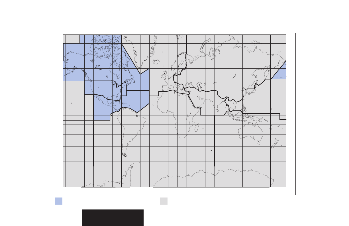
International Data Base primary areaNorth American Data Base primary area
Figure 2-1 KLX 135 Data Base Geographical Region

KLX 135 Pilot’s Guide Data Base
2-1 Effective Date 3/94006-08751-0000 Rev 0
Data Base
Chapter 2
2.DATA BASE
2.1. DATA BASICS
The data base provides two primary functions. First, it makes pilot
interface with the GPS sensor much easier. Rather than having to
manually look up and then enter the latitude and longitude for a spe-
cific waypoint, it allows you to merely enter a simple waypoint
identifier. The data base automatically looks up and displays the lati-
tude and longitude associated with the identifier. It should be obvious
that the data base saves a lot of tedious latitude/longitude entry and
also greatly reduces the potential for data input mistakes.
The second function of the data base is that it serves as a very con-
venient means to store and easily access aeronautical information.
Want to know the name of the airport, the nearest city, or the airport
altitude? Just unleash the power of the KLX 135 and display the
information right on the screen.
2.2. DATA BASE CONTENTS AND COVERAGE AREAS
There are two data base coverage areas available for the KLX 135.
One is referred to as the “North American” data base and the other is
referred to as the “International” data base.
The International Civil Aviation Organization (ICAO) and Aeronautical
Radio, Inc. (ARINC) break the world into the ten geographic regions
shown in figure 2-1. The KLX 135 North American data base con-
tains aeronautical information for the group of ICAO regions
consisting of Canada, USA, and Latin America. Likewise, the
International data base also provides information for the group of
ICAO regions consisting of Europe, East Europe, Africa, Mid East,
Pacific, South Pacific, and South America.
Both data bases contain complete information for all VORs and
NDBs in their respective coverage area. The data base also contains
public use and military airports which have any runway at least 1000
feet in length.

Data Base
2-2
Effective Date 3/94 006-08751-0000 Rev 0
Data Base
Chapter 2
The following is a listing of the KLX 135 North American and
International data base contents:
AIRPORTS
Identifier
Name
City, State or Country
Use type (if military)
Latitude and Longitude
Elevation
Communication frequencies
VORs
Identifier
Name
Frequency
Latitude and Longitude
Magnetic variation
NDBs
Identifier
Name
Frequency
Latitude and Longitude
(Note - Outer Compass Locators are not included in the data base)
250 USER DEFINED WAYPOINTS
Identifier
Latitude and Longitude

KLX 135 Pilot’s Guide Data Base
2-3 Effective Date 3/94006-08751-0000 Rev 0
Data Base
Chapter 2
2.3. ICAO IDENTIFIERS
Waypoints are stored in the KLX 135 database almost exclusively by
their ICAO identifiers. ICAO (International Civil Aviation
Organization) is an internationally accepted reference for the data. In
almost all cases the proper ICAO identifiers may be taken directly
from Jeppesen Sanderson or government aeronautical charts.
Airport identifiers in the contiguous United States, Alaska, and
Canada are special cases in the ICAO system. Many airport identi-
fiers for these areas have four letters beginning with a prefix letter
that corresponds to the geographic area in which it is located. The
prefix letter for the contiguous U.S. is “K”. Thus, the identifier for
Dallas/Fort Worth International Airport is KDFW, not DFW (which
would be identical to the VOR identifier). Likewise, the identifier for
Orlando Executive Airport is KORL while the VOR identifier if ORL.
The prefix letter for Canada is “C” and for Alaska is “P”.
NOTE: There are several exceptions in Alaska. In many cases, air-
ports with three letter identifiers receive the prefix “P”, but there are
many that don’t. The most reliable method of determining an Alaska
airport identifier is to look it up from the airport name or city. See sec-
tion 4.7.4, “Selecting Waypoints by Name or City”.
Incidentally, you can program the KLX 135 to default to a certain
letter (such as “K”) when you are entering a waypoint identifier. See
section 4.4.2, “Data Entry” to learn about this handy feature.
Not all airport identifiers receive the prefix letter. Airport identifiers
which are combinations of letters and numbers do not apply to the
prefix rule. Examples of airport identifiers not using the prefix are
3C2, 7TX6, and M33.
So remember, if you are entering or looking for an airport
identifier that is all letters (no numbers) then it will begin with a
“K” prefix in the contiguous U.S., a “P” in Alaska (in some
cases), or a “C” in Canada. If there are numbers in the identifier
then a prefix is not used. For other areas of the world the airport
identifier stored in the KLX 135 data base is identical to how it is
charted.
2.4. UPDATING THE DATA BASE
The information stored in the data base would eventually become
obsolete if there wasn’t some means to update it. For example, new
airports open, navaids can move or change frequency,
communication frequencies can change, and on and on.

The data base is updated by means of a 3.5-inch diskette supplied by
AlliedSignal and an IBM-compatible personal computer. This method
does not have to involve removing the KLX 135 from the aircraft’s
instrument panel. A jack, usually mounted in the aircraft’s instrument
panel, provides a means of interfacing the KLX 135 with the comput-
er via an interface cable. The diskettes are not returned to
AlliedSignal.
Every 28 days, AlliedSignal receives new NavData information from
Jeppesen Sanderson. This information is processed and down-
loaded onto diskettes. AlliedSignal makes the update service
available to you in a choice of several subscription or random update
programs. See section 2.6 for details on these programs.
NOTE: AlliedSignal sends the update so that it arrives prior to the
next effective date. The new update may be installed any time prior
to the effective date and the KLX 135 will use the previous data up to
the effective date and automatically begin using the new data on the
effective date.
In order to use the update program you must have access to a com-
puter having a disk drive capable utilizing 3.5-inch 1.44 megabyte
high density diskettes. If you wish to perform updates in the cockpit,
an optional PC Interface kit must be used. Included in the kit is an
interface cable that plugs into both the computer and into the data
loader jack. The data loader jack is included with the KLX 135
installation kit and is typically installed in the aircraft’s instrument
panel.
CAUTION: The data base must be updated only while the air-
craft is on the ground. The KLX 135 does not perform any
navigation function while the data base is being updated. Since
a data base update takes approximately 10 minutes it is a good
idea to turn off all electrical equipment on the aircraft except for
the KLX 135 to avoid running down the aircraft battery.
NOTE: The diskettes sent to you can only be used to update one
KLX 135, although they can update that specific unit numerous times.
The first time the diskettes are used in an update operation, a unique
identification code from the KLX 135 being used is uploaded to the
diskettes. These diskettes may be used in this specific KLX 135 an
unlimited number of times which could be required if you switch back
and forth between the North American and International data bases
during one update cycle. These diskettes may not, however, be used
to update other KLX 135s. This update protection ensures that
Jeppesen Sanderson is properly compensated for the use of their
NavData.
Data Base
2-4Effective Date 3/94 006-08751-0000 Rev 0
Data Base
Chapter 2

To update the KLX 135 data base:
1. Plug the 9 pin female connector end of the interface cable into a
COM serial port of the computer. If the computer has COM 1
and COM 2 serial ports, either may be used. Some computers
use a 9 pin COM serial port connector while other computers use
a 25 pin connector. If the computer being used has a 9 pin con-
nector, the interface cable connector will plug directly into the
computer’s 9 pin connector. If the computer’s COM serial port
uses a 25 pin connector, use the 25 pin to 9 pin adapter included
in the PC interface kit to adapt the interface cable’s connector to
the computer’s connector.
2. If you are using the PC interface kit in the cockpit, plug the other
end of the interface cable (4 conductor male connector) into the
data loader jack that is mounted in the aircraft panel.
3. Insert the diskette into the computer’s disk drive. Turn on the
computer being used for the data base update. The program on
the disk will automatically “boot” (load) and the computer screen
will display “Ready” when the computer is ready to continue with
the data base update operation.
4. Turn on the KLX 135. Press F
as required to approve the Self
Test, Initialization, VFR, and Data
Base pages. Use the right outer
knob to select the Setup (SET)
type pages and the right inner
knob to select the SET 3 page
(figure 2-2).
5. Press B. Update Pub DB? will
now be inverse video as in
figure 2-3.
6. Press F. The estimated load
time in minutes is now displayed
(figure 2-4).
NOTE: In step 6, repeated pressing
E
will terminate the update process
and bring the display back to the orig-
inal SET 3 page shown in figure 2-2.
7. Press Fto acknowledge the estimated load time and begin the
erasing of the existing data base. The unit will now display
KLX 135 Pilot’s Guide Data Base
2-5 Effective Date 3/94006-08751-0000 Rev 0
Data Base
Chapter 2
127.00 Update data
119.40 base on
>Leg ground only:
SET 3 Update pub DB?
APT VOR NDB SUP ACT NAV FPL CAL SET OTH
Figure 2-2
127.00 Update data
119.40 base on
#>Leg ground only:
CRSR Update pub DB?
APT VOR NDB SUP ACT NAV FPL CAL SET OTH
Figure 2-3
APT VOR NDB SUP ACT NAV FPL CAL SET OTH
127.00 Estimated load
119.40 time: 5 min
#>Leg
CRSR Approve?
Figure 2-4

Data Base
2-6Effective Date 3/94 006-08751-0000 Rev 0
Data Base
Chapter 2
Erasing data base. After the
data base has been erased, the
loading of the new data automati-
cally begins. As the new data is
being loaded, the percentage of
transfer is displayed (figure 2-5).
8.The KLX 135 will indicate when
the data base update is complete
as shown in figure 2-6. You may
either turn the KLX 135 off at this
point or press Fto restart the
KLX 135.
9.Remove the interface cable. Remove the disk from the com-
puter. Turn off the computer.
The chances are small of having difficulty updating the data base
but—
If you have a problem:
•First check that the interface cable is properly connected and that
the computer is turned on. If there is a problem with the
connection or the computer the KLX 135 will display Data
Loader Not Ready. When the problem is corrected this prompt
is removed and the update operation can continue from where it
left off.
•If an internal test fails after the data has been loaded, the
KLX135 will display Checksum Error, Data Base Invalid.
Press F to acknowledge. The KLX 135 will then display Data
Base Update Failed, Retry?Use the right outer knob to posi-
tion the cursor over the desired choice and press F.
•There are other error messages that may be displayed. If you
have a problem that you can’t resolve, write down any error
messages to aid your AlliedSignal Service Center in identifying
the problem.
2.5. USER DEFINED DATA BASE
In addition to the published data base of airports, VORs, and NDBs
stored in the Jeppesen data base, you may create up to 250 other
user-defined waypoints. Section 5.2.1, “Creating User-defined
waypoints” describes this further.
APT VOR NDB SUP ACT NAV FPL CAL SET OTH
127.00 Programming
119.40 data base
>Leg 95% complete
CRSR
Figure 2-5
APT VOR NDB SUP ACT NAV FPL CAL SET OTH
127.00 Published data
119.40 base update
#>Leg complete
CRSR Acknowledge?
Figure 2-6
Table of contents


