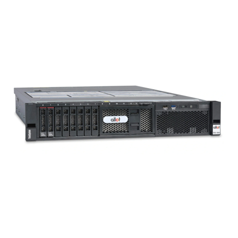
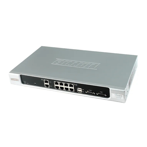
Allot SG-9100 Installation instructions

Service Gateway
SG-9100
Hardware Guide


Allot SG-9100 Hardware Guide
v
Important Notice
Allot Communications Ltd. ("Allot") is not a party to the purchase agreement under which Allot Service Gateway
9100 was purchased, and will not be liable for any damages of any kind whatsoever caused to the end users using this
manual, regardless of the form of action, whether in contract, tort (including negligence), strict liability or otherwise.
SPECIFICATIONS AND INFORMATION CONTAINED IN THIS MANUAL ARE FURNISHED FOR
INFORMATIONAL USE ONLY, AND ARE SUBJECT TO CHANGE AT ANY TIME WITHOUT NOTICE, AND
SHOULD NOT BE CONSTRUED AS A COMMITMENT BY ALLOT OR ANY OF ITS SUBSIDIARIES. ALLOT
ASSUMES NO RESPONSIBILITY OR LIABILITY FOR ANY ERRORS OR INACCURACIES THAT MAY APPEAR IN
THIS MANUAL, INCLUDING THE PRODUCTS AND SOFTWARE DESCRIBED IN IT.
Please read the End User License Agreement and Warranty Certificate provided with this product before using the product.
Please note that using the products indicates that you accept the terms of the End User License Agreement and Warranty
Certificate.
WITHOUT DEROGATING IN ANY WAY FROM THE AFORESAID, ALLOT WILL NOT BE LIABLE FOR ANY
SPECIAL, EXEMPLARY, INDIRECT, INCIDENTAL OR CONSEQUENTIAL DAMAGES OF ANY KIND,
REGARDLESS OF THE FORM OF ACTION WHETHER IN CONTRACT, TORT (INCLUDING NEGLIGENCE),
STRICT LIABILITY OR OTHERWISE, INCLUDING, BUT NOT LIMITED TO, LOSS OF REVENUE OR
ANTICIPATED PROFITS, OR LOST BUSINESS, EVEN IF ADVISED OF THE POSSIBILITY OF SUCH DAMAGES.
Copyright
Copyright © 1997-2017 Allot Communications. All rights reserved. No part of this document may be reproduced,
photocopied, stored on a retrieval system, transmitted, or translated into any other language without a written permission and
specific authorization from Allot Communications Ltd.
Trademarks
Products and corporate names appearing in this manual may or may not be registered trademarks or copyrights of their
respective companies, and are used only for identification or explanation and to the owners' benefit, without intent to infringe.
Allot and the Allot Communications logo are registered trademarks of Allot Communications Ltd.
NOTE: This equipment has been tested and found to comply with the limits for a Class A digital device, pursuant to Part 15 of
the FCC Rules. These limits are designed to provide reasonable protection against harmful interference when the equipment
is operated in a commercial environment. This equipment generates, uses, and can radiate radio frequency energy and, if not
installed and used in accordance with the instruction manual, may cause harmful interference to radio communications.
Operation of this equipment in a residential area is likely to cause harmful interference in which case the user will be
required to correct the interference at his own expense.
Changes or modifications not expressly approved by Allot Communication Ltd. could void the user's authority to operate the
equipment.

Allot SG-9100 Hardware Guide
vi
Version History
Each document has a version and a build number. You can tell the exact version and build
of this document by checking the table below. Details of this document version are
contained in the top row of the table below.
Document updates are released in electronic form from time to time and the most up to date
version of this document will always be found on Allot’s online Knowledge Base. To check
for more recent versions, login to the support area www.allot.com/support.html and from
the knowledgebase tab, enter the title of this document into the search field.
Doc
Release
Document Build
Date
Summary of
Changes
1
b3
18/05/17
1
b2
27/04/17
1
b1
24/01/17

Allot SG-9100 Hardware Guide
vii
TABLE OF CONTENTS
Important Notice ........................................................................................................................... v
Version History............................................................................................................................. vi
TABLE OF CONTENTS............................................................................................................vii
CHAPTER 1: INTRODUCING THE SG-9100................................................... 1-1
Planning Your Deployment.......................................................................................................1-2
Packing List.................................................................................................................................1-2
Cabling and Transceivers..........................................................................................................1-3
Cable types................................................................................................................................1-3
Transceivers.............................................................................................................................. 1-4
Connectors................................................................................................................................1-4
CHAPTER 2: CONNECTORS AND LEDS....................................................... 2-1
Packing List..............................................................................................................................2-1
Front Panel................................................................................................................................2-2
Rear Panel.................................................................................................................................2-3
CHAPTER 3: BYPASS..................................................................................... 3-1
External Bypass Unit..................................................................................................................3-1
HD 8 Fiber or Copper Bypass Unit...........................................................................................3-2
HD 16 Fiber Bypass Unit..........................................................................................................3-3
External Bypass Control Cabling .............................................................................................3-5
CHAPTER 4: POWER CONNECTIVITY PLANNING....................................... 4-1
Power Source Requirements .....................................................................................................4-1
Electrical GroundingRequirements..........................................................................................4-2
Cable and Cord Specifications..................................................................................................4-2
AC Power Cord Specifications................................................................................................. 4-2
CHAPTER 5: PREPARATION AND INSTALLATION ..................................... 5-1
Unpacking the SG-9100 .............................................................................................................5-1
Mounting the SG-9100...............................................................................................................5-2
Space and Airflow Requirements............................................................................................. 5-2
Rack Mounting the Service Gateway
.....................................................................................5-2
CHAPTER 6: DEPLOYING THE SG-9100....................................................... 6-1
Connecting Network Traffic......................................................................................................6-1
Configuring Active Redundancy...............................................................................................6-2
Physical Connections................................................................................................................6-3
Configuration............................................................................................................................6-4
Powering Up the SG-9100..........................................................................................................6-5
Initial Configuration ..................................................................................................................6-6

Allot SG-9100 Hardware Guide
viii
Accessing the SG-9100 via Physical Ports...............................................................................6-6
Accessing the SG-9100 via the TSM........................................................................................6-6
CHAPTER 7: TECHNICAL INFORMATION .................................................... 7-1
Technical Specifications.............................................................................................................7-1
Safety Certifications...................................................................................................................7-2
Environmental Certifications....................................................................................................7-2
Laser Safety Requirements........................................................................................................7-3
Laser Classification...................................................................................................................7-3
Laser Information .....................................................................................................................7-3
Laser Safety Statutory Warning................................................................................................7-3
Training for Laser Safety..........................................................................................................7-3
Laser Device Operating Precautions......................................................................................... 7-3

Allot SG-9100 Hardware Guide
ix
TABLE OF FIGURES
Figure 1-1 –Full Duplex LC Connector ......................................................................................1-4
Figure 2-1 –SG-9100...................................................................................................................2-1
Figure 2-2 –SG-9100 Front Panel Buttons and LEDs.................................................................2-2
Figure 2-3 –SG-9100 Rear Panel ................................................................................................2-3
Figure 2-4 –NETWORK Links ................................................................................................... 2-3
Figure 2-4 –Fiber Cable Release Tool.........................................................................................2-4
Figure 2-6 –SG 9100 AC Power Feed......................................................................................... 2-5
Figure 3-1: HD 8 Fiber Bypass Unit ............................................................................................3-2
Figure 3-2: HD 16 Fiber Bypass Unit ..........................................................................................3-3
Figure 3-3: Allot USB Bypass Cable ..........................................................................................3-5
Figure 4-1: IEC-320 C13 to C14 Power Cord.............................................................................4-2
Figure 6-1 –Active Redundancy Links........................................................................................ 6-3
Figure 6-2 –SG-9100 Interfaces..................................................................................................6-3
Figure 6-3 –System Information .................................................................................................6-7
Figure 6-4 –TSM Settings...........................................................................................................6-7
Figure 6-5: TSM System Status Screen........................................................................................6-9
Figure 6-6: Remote Console......................................................................................................... 6-9


Allot SG-9100 Hardware Guide
1-1
Chapter 1: Introducing the SG-9100
Allot Service Gateway 9100 provides a powerful service delivery platform in an Intel-
based appliance, designed especially for cloud data center, enterprise, and ISP networks.
Its small-footprint is equipped with the same rich features and functions as our chassis-
based Allot Service Gateway, enabling you to roll out Security as a Service as well as
other revenue-generating services rapidly and cost-effectively, while you lower your
total cost of ownership and accelerate ROI.
Powerful and cost-efficient service delivery platform
Real-time Layer-7 application visibility, policy enforcement and charging
Real-time visibility of encrypted traffic
Supporting turnkey Security as a Service solutions
Deployment and management across any access
Easy installation and pay-as-you-grow scalability

Chapter 1: Introducing the SG-9100
Allot SG-9100 Hardware Guide
1-2
Planning Your Deployment
This equipment is intended to be installed by trained service personnel and in
environments where access by unauthorized personnel is restricted (Restricted Access
Location). The SG-9100 complies with the requirements for operator access.
Please note that the power resources used by the SG-9100 must be planned and installed
by a qualified electrical engineer only. Before installing or using the SG-9100, please
read all Safety Information carefully to avoid electrical hazards that can result in injury
or loss of equipment.
In addition, be aware that all network and power connections to the SG-9100 are from
the rear of the device so there must be adequate space behind the unit for safe access at
all times.
Packing List
Verify that the following items are included with the SG-9100:
SG-9100 System
Pair of AC power IEC-320 C13/C14 cables
One or Two Bypass units (Multi-Mode, Single Mode or Copper)
and appropriate cables to connect to the SG-9100
Up to 12 SFP/SFP+ Optical Transceivers (either SR, LR, SX or
LX5 Fiber) or Copper transceivers.
NOTE All Transceivers MUST be provided by Allot specifically for the
SG-9100. Any other Transceivers will not function in the SG-
9100.
BYPASS USB Control Cable(s) –number depends on number of
BYPASS units ordered (Allot P/N C245055)
Ethernet cable straight CAT6 RJ45_2_RJ45 3m for management
(Allot P/N C243010)
NOTE Cables to connect from the Bypass Unit to the Network are not
provided by Allot.

Chapter 1: Introducing the SG-9100
Allot SG-9100 Hardware Guide
1-3
Cabling and Transceivers
Cable types
CONNECTIONS
MM CABLE TYPE
SM CABLE TYPE
COPPER CABLE
TYPE
Management
Port
Ethernet (CAT 6)
(Allot P/N C243010
included)
Dual RJ-45
Connectors
Ethernet (CAT 6)
(Allot P/N C243010
Included) or Fiber.
Dual RJ-45
Connectors
Ethernet (CAT 6)
(Allot P/N C243010
Included) or Fiber.
Dual RJ-45 Connectors
Between Bypass
and System
8P Bypass
8 x Standard 62.5/125
MM fiber optic cross
cable.
(Allot P/N C411055
included).
Full Duplex LC to
Full Duplex LC
Connectors
16P Bypass:
16 x Standard
62.5/125 MM fiber
optic cross cable
(Allot P/N C411030
included).
Full Duplex LC to
Full Duplex LC
Connectors
8P Bypass
8 x 9/125 SM fiber
optic cross cable.
(Allot P/N C411029
included).
Full Duplex LC to
Full Duplex LC
Connectors
16P Bypass:
16 x 9/125 SM fiber
optic cross cable.
(Allot P/N C411029
included).
Full Duplex LC to
Full Duplex LC
Connectors
8P Bypass:
8 x CABLE STR CAT6
2x RJ45 1M
(Allot PN
C411019 included).
Dual RJ45 Connectors.
Service
Gateway’s
Bypass
Connector to
Bypass Unit
USB Bypass Cable
Allot P/N C245055
(Included).
USB to DB-9
Connectors.
USB Bypass Cable
Allot P/N C245055
(Included).
USB to DB-9
Connectors.
USB Bypass Cable Allot
P/N C245055
(Included).
USB to DB-9
Connectors.
Between Bypass
Unit and
Network
Standard 62.5/125 or
50/125 MM fiber
optic cross cable
(Not Included).
Full Duplex LC to
Full Duplex LC
Connectors.
Standard 9/125 SM
fiber optic cross
cable
(Not Included).
Full Duplex LC to
Full Duplex LC
Connectors
STR CAT6 Copper
cabling (Not Included).
Dual RJ45 Connectors

Chapter 1: Introducing the SG-9100
Allot SG-9100 Hardware Guide
1-4
Transceivers
NOTE All Transceivers MUST be provided by Allot specifically for the
SG-9100. Any other Transceivers will not function in the SG-
9100.
The following transceivers (available from Allot) may be used with the SG-9100:
10G Fiber
SG-TRNSCV-10G-SR
SG-TRNSCV-10G-LR
1G Fiber (Dual Rate)
SG-TRNSCV-1G-SX-A
SG-TRNSCV-1G-LX5-A
1G Copper (10/100/1000)
SG-TRNSCV-1G-COP-A
NOTE 1G Copper interfaces may only use the 8 Port Bypass Unit if
available, limiting the number of ports which may be used on
the SG-9100.
Connectors
The SG-9100’s 8-port and 16-port Fiber Bypass Units use Multi Mode fiber (MM) or
Single Mode fiber (SM) dual LC Connectors. The 24-port Fiber Bypass unit uses MTP
Fiber connectors. The 8-port Copper Bypass Unit uses dual RJ45 connectors.
Figure 1-1 –Full Duplex LC Connector
NOTE Color and appearance of actual connectors may vary.

Allot SG-9100 Hardware Guide
2-1
Chapter 2: Connectors and LEDs
Allot Service Gateway 9100 (SG-9100) provides a high performance service delivery
platform with rich functionality in an efficient, small-footprint appliance. With high-
density 10 Gigabit Ethernet connectivity and 140 Gbps of throughput, the platform
allows enterprises, cloud data centers and ISP networks to satisfy the ever-growing
demand for Internet bandwidth and network-based services in cost-efficient manner.
Figure 2-1 –SG-9100
Packing List
Verify that the following items are included with the SG-9100:
SG-9100 System. The SG-9100 is provided with the Allot Service
Gateway software pre-installed.
Pair of AC power IEC-320 C13/C14 cables
One or Two Bypass units (Multi-Mode, Single Mode or Copper)
and appropriate cables to connect to the SG-9100
Up to 12 SFP/SFP+ Optical Transceivers (either SR, LR, SX or
LX5 Fiber) or Copper transceivers.
NOTE All Transceivers MUST be provided by Allot specifically for the
SG-9100. Any other Transceivers will not function in the SG-
9100.
BYPASS USB Control Cable(s) –number depends on number of
BYPASS units ordered (Allot P/N C245055)
Ethernet cable straight CAT6 RJ45_2_RJ45 3m for management
(Allot P/N C243010)
NOTE Cables to connect from the Bypass Unit to the Network are not
provided by Allot.

Chapter 2: Connectors and LEDs
Allot SG-9100 Hardware Guide
2-2
Front Panel
Front Panel Buttons and LEDS Description
Figure 2-2 –SG-9100 Front Panel Buttons and LEDs
DESCRIPTION
STATUS
Network Status
L
E
D
Flashing = Network is Connected and Active
Off = The System is Disconnected
System Health
L
E
D
Solid Amber = System Fault
Flashing Amber = The SG is Initializing
Off = The System is working normally
Power
L
E
D
Solid green
=
Power is On
Off
=
Power is Off
Off
=
No network a
c
ti
v
i
ty
Front Panel Connectors
There are no connectors on the front panel of the SG-9100.
NOTE Since the SG-9100 has only 2 USB ports on the read of the
server, these ports are designated for bypass unit connectivity
only. They cannot be used for anything else (such as
keyboard/mouse), even if there is no bypass unit being
connected to any of the ports. This means that the initial IP
configurations will have to be done using the TSM. After that
everything can be done using SSH.
Network Status
LED
System Health
LED
Power Button
and LED
System ID
Button

Chapter 2: Connectors and LEDs
Allot SG-9100 Hardware Guide
2-3
Rear Panel
Figure 2-3 –SG-9100 Rear Panel
Rear Panel Connectors
10G/1G NETWORK LINKS (P1 –P4): There are 4 x 1G/10G Ethernet
network interfaces on each of the lower 2 PCIe cards (P1 and P2) and 2 x
1G/10G Ethernet network interfaces on each of the upper two PCIe cards (P3 and
P4), used for Network traffic, which can support 1G/10G SFP+ fiber or 1G RJ45
Copper interfaces.
NOTE The two upper PCIe cards (P3 and P4) have transceivers
loaded in upside down.
Figure 2-4 –NETWORK Links
Each PCIe card has four ports which may be used for either 1G/10G fiber or 1G
copper network or steering interfaces. On all ports the TX connection is on the
left and the RX connection is on the right. In the NetXplorer, SG-9100 ports are
labeled L1 through L12.
Transceivers for multiple interface types may not be installed on the same card
but a mixture of cards using 1G Fiber transceivers, 10G Fiber transceivers and
1G Copper transceivers may be installed in the same SG-9100.
For example, in a single SG-9100, PCIe card P1 can use 1G Copper transceivers,
P2 can use 10G Fiber transceivers and P3 can use 1G Fiber transceivers, but you
can’t have P1:L1 (the first link on PCI card 1) use 1G copper and P1:L2 use 10G
fiber since each card can support a transceiver type.
MONITOR
PORT
BYPASS
POWER
SUPPLIES
M1
L1
L2
L3
L4
TSM
PORT
M2
P1 (L1-L4)
P2 (L5-L8)
P3 (L9-L10)
P4 (L11-L12)
Fiber Cable
Release Tool

Chapter 2: Connectors and LEDs
Allot SG-9100 Hardware Guide
2-4
When removing a transceiver use the Fiber Cable Release Tool, located on the
rear panel of the unit. Slide the tool into the slot at the bottom of the transceiver
and slowly draw the unit out of the chassis.
Figure 2-5 –Fiber Cable Release Tool
LINK/ACT LEDs for each connection are located together to the left of the
interfaces.
NOTE 1G Copper interfaces may only use the 8 Port Bypass Unit,
limiting the number of ports which may be used on the SG-
9100 with Copper.
Ports should be connected from right to left on each card. For
example, on Card 1 L4 should be connected first, followed by
L3, L2 and finally L1.
M1 & M2 are two RJ-45 connectors (1G Copper) which may be used for system
monitoring and maintenance. M2 acts as a redundant port for M1.
Rear USB Ports should only be used to connect the SG-9100 to the Bypass unit
ONLY.
TSM Port is used to connect the TSM system to the Network. For more
information see Accessing the SG-9100 via the TSM on page 6-6.
CAUTION Each Rear USB connectors should ONLY be connected to a
single Allot Bypass Units. The bypass cable should only be
connected/disconnected when the system is powered down.
Power Supply
The SG-9100 contains two built in power supply modules and a dual line feed for
Redundancy purposes. Each line feed drives one power supply. It is possible for the unit
to operate normally with only one of the two power supplies active.

Chapter 2: Connectors and LEDs
Allot SG-9100 Hardware Guide
2-5
NOTE The AC power supply automatically adapts to voltages
between 100 V and 240 V, 50/60 Hz.
Figure 2-6 –SG 9100 AC Power Feed
Power Supply LEDs
DESCRIPTION
STATUS
Power Input (AC)
L
E
D
Solid Green = The Power Supply is connected to the AC
Power Source
Off = The Power Supply is disconnected from the AC
Power Source
Power Output (DC)
L
E
D
Solid Green = The SG-9100 is On or the Power Supply is
working Normally.
Blinking Green = The Power Supply is on Redundancy
Mode.
Off = The SG-9100 is Off or the Power Supply is
malfunctioning.
Fault
L
E
D
Solid Amber = The Power Supply has failed
Off = The Power Supply is working normally
Fault LED
Power Output
LED
Power Input
LED


Allot SG-9100 Hardware Guide
3-1
Chapter 3: Bypass
External Bypass Unit
The SG-9100 operates with an external Bypass Unit. The Bypass Unit is a mission-
critical subsystem designed to ensure network connectivity at all times. The Bypass
mechanism provides "connectivity insurance" in the event of a subsystems failure. Each
Allot Bypass unit features low insertion loss (< 1dB) in both Normal mode and Bypass
mode and fast switching time (< 10mSec) between modes. A Service Gateway unit
Network ports must be connected to the appropriate External Bypass Unit. This is to
ensure continuous service in the event of failure. The Service Gateway should be
ordered with appropriate Bypass Units considering total number of ports that need
bypass protection and Fiber interface Type (Multi-Mode / Single-Mode).
A single HD 16 Fiber Bypass unit supports up to 8 links (16 ports) and an HD 8 Fiber
Bypass Unit supports up to 4 links (8 ports). In terms of Management, all Bypass units
are connected to the SG-9100 via a single USB cable.
NOTE If you have mix of Single-Mode and Multi-Mode optical
interfaces in a single SG-9100 system, then you will need to
split them into groups and connect them to appropriate
Bypass according to interface type. i.e. all Single-Mode ports
(LR) should be connected to Single-Mode Bypass SG-BP-EXT-
16P-SM-A or SG-BP-EXT-8P-SM-A, All Multi-Mode ports (SR)
should be connected to Multi-Mode Bypass SG-BP-EXT-16P-
MM-A or SG-BP-EXT-8P-MM-A.
ATTENTION Ports that are used for steering should not be routed through
Bypass.
The following bypass units are supported by the SG-9100:
PRODUCT NUMBER
DESCRIPTION
SG-BP-EXT-16P-MM-A
HD 16 Multimode Fiber Bypass
SG-BP-EXT-16P-SM-A
HD 16 Single-mode Fiber Bypass
SG-BP-EXT-8P-MM-A
HD 8 Multimode Fiber Bypass
SG-BP-EXT-8P-MM-50UM-A
HD 8 MM Fiber Bypass, 50/125 um
SG-BP-EXT-8P-SM-A
HD 8 Single-mode Fiber Bypass
SG-BP-EXT-8P-COP-A
HD 8 Copper Bypass

Chapter 3: Bypass
Allot SG-9100 Hardware Guide
3-2
HD 8 Fiber or Copper Bypass Unit
The HD 8 Bypass Unit (previously known as the Allot Multi-Port Bypass) can work in
conjunction with all SG-9100 Configuration and is available with Fiber or Copper
interfaces.
Figure 3-1: HD 8 Fiber Bypass Unit
NOTE Use Multi-Mode 62.5μmor Single-Mode 9μm fiber optic cables
CROSS with LC-LC Duplex connectors (not provided) to
connect ports of the switch and the router.
The HD 8 Bypass Unit includes connectors for up to 4 links on the SG-9100. In
addition, the HD 8 Bypass Unit includes two D-type 9-pin connectors (DB-9) for
connection to the SG-9100 via special DB-9/USB cables (available from Allot).
An HD 8 Bypass Unit supports up to 8 ports (4 links).
The HD 8 Bypass Unit is a passive optical device with no need for external power
connection. It is powered by the SG-9100 as long as it is Active. It will move
automatically to bypass mode when SG-9100 is powered off, or by being forced to
bypass mode as protective action is taken. There is no way to have a single link go into
bypass independently. When moving to Bypass mode all links are switched into
Bypass.
NOTE 1G Copper interfaces must be enabled via CLI command. See
Configuring the SG-9100 for more information.
1G Copper interfaces may only use the 8 Port Bypass Unit is
available, limiting the number of ports which may be used on
the SG-9100.
HD 8 Bypass Unit LEDS Description
The following indicators can be used to identify the operation of the blade:
Mode LED is STEADY GREEN when the Bypass Unit is operating normally
and OFF when the Link is in Bypass mode.
Mode LED
Links 1-4 to
Network
Secondary
Primary
Links 1-4 to the
SG-9500
Other manuals for SG-9100
1
Table of contents
Other Allot Gateway manuals

