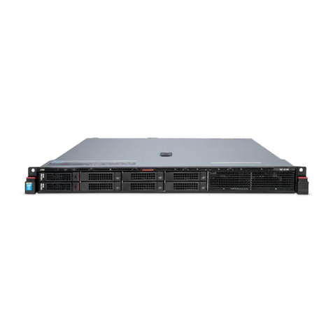
Allot SG-9100 Installation instructions

SG-9100
Hardware Guide

SG-9100 Hardware Guide
ii SG-9100 Hardware Guide
Version History
Each document has a version and a build number. You can tell the exact version and
build of this document by checking the top row of the table below.
Document updates are released in electronic form from time to time and the most up to
date version of this document will always be found on Allot’s online Knowledge Base.
Doc
Revision
Internal
Build
Published
Summary of Changes
2 r2b7 17.11.19 Copper Bypass added, Transceivers information
added, general updates

SG-9100 Hardware Guide
iii SG-9100 Hardware Guide
Contents
1Introducing the SG-9100 ...............................................................................................1-1
1.1 Planning Your Deployment...............................................................................1-2
1.2 Packing List........................................................................................................1-2
SG-9100 V2 ..........................................................................................1-2
SG-9100 V1 ..........................................................................................1-2
1.3 Cabling and Transceivers ..................................................................................1-4
Cable types ..........................................................................................1-4
Transceivers.........................................................................................1-5
Connectors ..........................................................................................1-5
2Connectors and LEDs.....................................................................................................2-1
2.1 SG-9100 V2........................................................................................................2-1
Front Panel ..........................................................................................2-1
Rear Panel............................................................................................2-3
2.2 SG-9100 V1........................................................................................................2-6
Front Panel ..........................................................................................2-6
Rear Panel............................................................................................2-8
3Bypass............................................................................................................................3-1
3.1 External Bypass Unit .........................................................................................3-1
HD 8 Fiber or Copper Bypass Unit.......................................................3-2
HD 16 Fiber Bypass Unit ......................................................................3-3
3.2 External Bypass Control Cabling .......................................................................3-5
4Power Connectivity Planning ........................................................................................4-1
4.1 Power Source Requirements ............................................................................4-1
Electrical GroundingRequirements.....................................................4-2
4.2 Cable and Cord Specifications ..........................................................................4-2
AC Power Cord Specifications .............................................................4-2
5Preparation and Installation..........................................................................................5-1
5.1 Unpacking the SG-9100 ....................................................................................5-1
5.2 Mounting the SG-9100 .....................................................................................5-2
Space and Airflow Requirements .......................................................5-2
Rack Mounting the Service Gateway
................................................5-3

SG-9100 Hardware Guide
iv SG-9100 Hardware Guide
6Deploying the SG-9100..................................................................................................6-1
6.1 Connecting Network Traffic..............................................................................6-1
6.2 Configuring Active Redundancy........................................................................6-5
Physical Connections...........................................................................6-6
Configuration.......................................................................................6-8
6.3 Powering Up the SG-9100...............................................................................6-10
6.4 Accessing the SG-9100....................................................................................6-11
Identifying the Revision.....................................................................6-11
Accessing the SG-9100 via Physical Ports .........................................6-11
Accessing the SG-9100 V1 via the TSM.............................................6-11
Accessing the SG-9100 V2 via the XCC/BMC.....................................6-14
6.5 Configuring the SG-9100.................................................................................6-22
Connecting Management Traffic.......................................................6-22
Changing the AOS Passwords............................................................6-23
7Technical Information ...................................................................................................7-1
7.1 Technical Specifications....................................................................................7-1
7.2 Environmental Specifications ...........................................................................7-3
7.3 Safety Certifications..........................................................................................7-3
7.4 Environmental Certifications ............................................................................7-3
7.5 Bypass Physical Specifications ..........................................................................7-3
7.6 Laser Safety Requirements ...............................................................................7-4
Laser Classification ..............................................................................7-4
Laser Information ................................................................................7-4
Laser Safety Statutory Warning ..........................................................7-4
Training for Laser Safety......................................................................7-4
Laser Device Operating Precautions ...................................................7-4

SG-9100 Hardware Guide
1Introducing the SG-9100
Allot Service Gateway 9100 provides a powerful service delivery platform in an
Intel-based appliance, designed especially for cloud data center, enterprise, and ISP
networks. Its small-footprint is equipped with the same rich features and functions
as our chassis-based Allot Service Gateway, enabling you to roll out Security as a
Service as well as other revenue-generating services rapidly and cost-effectively,
while you lower your total cost of ownership and accelerate ROI.
•Powerful and cost-efficient service delivery platform
•Real-time Layer-7 application visibility, policy enforcement and charging
•Real-time visibility of encrypted traffic
•Supporting turnkey Security as a Service solutions
•Deployment and management across any access
•Easy installation and pay-as-you-grow scalability
The SG-9100 comes in two different revisions. V2 is a 2U unit with 16 ports while
V1 is a 1U unit with 12 ports.
When logged into the SG-9100 via TSM/XCC or SSH, run the following command to
check with revision this model is:
getinfo
When the System Information Menu appears, select number 3 to see Vendor
information.
Under Product Name, the SG-9100 V2 will be listed as a ThinkSystem SR550, while
V1 will be listed as a ThinkServer RD550.

Introducing the SG-9100
1-2 SG-9100 Hardware Guide
1.1 Planning Your Deployment
This equipment is intended to be installed by trained service personnel and in
environments where access by unauthorized personnel is restricted (Restricted
Access Location). The SG-9100 complies with the requirements for operator access.
Please note that the power resources used by the SG-9100 must be planned and
installed by a qualified electrical engineer only. Before installing or using the SG-
9100, please read all Safety Information carefully to avoid electrical hazards that
can result in injury or loss of equipment.
In addition, be aware that all network and power connections to the SG-9100 are
from the rear of the device so there must be adequate space behind the unit for
safe access at all times.
1.2 Packing List
Verify that the following items are included with the SG-9100:
SG-9100 V2
1. SG-9100 V2 System
2. Pair of AC power IEC-320 C13/C14 cables
3. Up to 16 SFP/SFP+ Optical Transceivers (either SR, LR, SX or LX5 Fiber) or
Copper transceivers.
Note: All Transceivers MUST be provided by Allot specifically for the SG-9100. Any
other Transceivers will not function in the SG-9100.
4. Ethernet cable straight CAT6 RJ45_2_RJ45 3m for management (Allot P/N
C243010)
Note Cables to connect from the Service Gateway to the Bypass are included with
the Bypass Unit. Cables to connect from the Bypass Unit to the Network are
not provided by Allot.
Note: The following components of the SG-9100 V2 are replaceable and hot
swappable: Power Supply Units and Hard Dick Drives.
The following components SG-9100 V2 are replaceable but NOT hot
swappable: NIC cards, RAM and RAID cards.
SG-9100 V1
1. SG-9100 V1 System
2. Pair of AC power IEC-320 C13/C14 cables

Introducing the SG-9100
1-3 SG-9100 Hardware Guide
3. Up to 12 SFP/SFP+ Optical Transceivers (either SR, LR, SX or LX5 Fiber) or
Copper transceivers.
Note: All Transceivers MUST be provided by Allot specifically for the SG-9100. Any
other Transceivers will not function in the SG-9100.
4. Ethernet cable straight CAT6 RJ45_2_RJ45 3m for management (Allot P/N
C243010)
Note Cables to connect from the Service Gateway to the Bypass are included with
the Bypass Unit. Cables to connect from the Bypass Unit to the Network are
not provided by Allot.

Introducing the SG-9100
1-4 SG-9100 Hardware Guide
1.3 Cabling and Transceivers
Cable types
CONNECTIONS MM CABLE TYPE SM CABLE TYPE COPPER CABLE TYPE
Management Port
Ethernet (CAT 6) (Allot
P/N C243010 included)
Dual RJ-45
Connectors
Ethernet (CAT 6)
(Allot P/N C243010
Included) or Fiber.
Dual RJ-45 Connectors
Ethernet (CAT 6)
(Allot P/N C243010
Included) or Fiber.
Dual RJ-45 Connectors
Between Bypass
and System
8P Bypass
8 x Standard 62.5/125
MM fiber optic cross
cable.
(Allot P/N C411055
included with Bypass).
Full Duplex LC to Full
Duplex LC
Connectors
16P Bypass:
16 x Standard 62.5/125
MM fiber optic cross
cable
(Allot P/N C411030
included with Bypass).
Full Duplex LC to Full
Duplex LC
Connectors
8P Bypass
8 x 9/125 SM fiber
optic cross cable.
(Allot P/N C411029
included with Bypass).
Full Duplex LC to Full
Duplex LC
Connectors
16P Bypass:
16 x 9/125 SM fiber
optic cross cable.
(Allot P/N C411029
included with Bypass).
Full Duplex LC to Full
Duplex LC
Connectors
8P Bypass:
8 x CABLE STR CAT6 2x RJ45
1M
(Allot PN C411019 included
with Bypass).
Dual RJ45 Connectors.
Service Gateway’s
Bypass Connector
to Bypass Unit
USB Bypass Cable Allot
P/N C245055
(Included with Bypass).
USB to DB-9
Connectors.
USB Bypass Cable
Allot P/N C245055
(Included with
Bypass).
USB to DB-9
Connectors.
USB Bypass Cable Allot P/N
C245055
(Included with Bypass).
USB to DB-9 Connectors.
Between Bypass
Unit and Network
Standard 62.5/125 or
50/125 MM fiber optic
cross cable
(Not Included).
Full Duplex LC to Full
Duplex LC
Connectors.
Standard 9/125 SM
fiber optic cross cable
(Not Included).
Full Duplex LC to Full
Duplex LC
Connectors
STR CAT6 Copper cabling
(Not Included).
Dual RJ45 Connectors

Introducing the SG-9100
1-5 SG-9100 Hardware Guide
Transceivers
Note: All Transceivers MUST be provided or approved by Allot specifically for the SG-
9100. Any other Transceivers will not function in the SG-9100.
The following transceivers (available from Allot) may be used with the SG-9100:
10G Fiber
•SG-TRNSCV-10G-SR
•SG-TRNSCV-10G-LR
1G Fiber (Dual Rate)
•SG-TRNSCV-1G-SX-A
•SG-TRNSCV-1G-LX5-A
1G Copper (10/100/1000)
•SG-TRNSCV-1G-COP-A
Note: 1G Copper interfaces may only use the 8 Port Bypass Unit if available, limiting
the number of ports which may be used on the SG-9100.
Connectors
The SG-9100’s 8-port and 16-port Fiber Bypass Units use Multi Mode fiber (MM) or
Single Mode fiber (SM) dual LC Connectors. The 24-port Fiber Bypass unit uses MTP
Fiber connectors. The 8-port Copper Bypass Unit uses dual RJ45 connectors.
Figure 1-1 – Full Duplex LC Connector
Note: Color and appearance of actual connectors may vary.

SG-9100 Hardware Guide
2Connectors and LEDs
Allot Service Gateway 9100 (SG-9100) provides a high performance service delivery
platform with rich functionality in an efficient, small-footprint appliance. With high-
density connectivity, the platform allows enterprises, cloud data centers and ISP
networks to satisfy the ever-growing demand for Internet bandwidth and network-
based services in cost-efficient manner.
2.1 SG-9100 V2
Figure 2-1 – SG-9100 V2
Front Panel
Front Panel Buttons and LEDS Description
Figure 2-2 – SG-9100 V2 Front Panel Buttons and LEDs
Power
Button and
LED
System ID
Button

Connectors and LEDs
2-2 SG-9100 Hardware Guide
DESCRIPTION STATUS
Power
L
E
D
Solid green
=
Power is On
Blinking = Initializing
Off
=
Power is Off
Front Panel Connectors
The USB Connectors on the front panel of the SG-9100 V2 are not in use at this
time.
Note: Since the SG-9100 has 2 USB ports on the rear of the server, these ports are
designated for bypass unit connectivity only. They cannot be used for anything
else (such as keyboard/mouse), even if there is no bypass unit being
connected to any of the ports. This means that the initial IP configurations will
have to be done using the XCC. After that everything can be done using SSH.

Connectors and LEDs
2-3 SG-9100 Hardware Guide
Rear Panel
Figure 2-3 – SG-9100 V2 Rear Panel
Rear Panel Connectors
•10G/1G NETWORK LINKS (P1 – P4): There are 4 x 1G/10G Ethernet
network interfaces on each of the 4 PCIe cards (P1 and P2) used for
Network traffic, which can support 1G/10G SFP+ fiber or 1G RJ45 Copper
interfaces.
Figure 2-4 – NETWORK Links
Each PCIe card has four ports which may be used for either 1G/10G fiber
or 1G copper network or steering interfaces. On all ports the TX
connection is on the left and the RX connection is on the right.
In the NetXplorer, SG-9100 ports are labeled Px.Ly where 'x' stands for the
PCIe slot number and 'y' stands for the port number within that PCIe slot.
For example, the second port on the third PCIe card (S3) will be identified
as P3.L2.
See the table below:
NETXPLORER
USAGE
NETXPLORER
USAGE
P1.L1
Int1
P3.L1
Int5
MONITOR
PORT
BYPASS
POWER
SUPPLIES
M1
L1
L2
L3
L4
TSM
PORT
M2
P3
P2
P1
P4
XCC PORT

Connectors and LEDs
2-4 SG-9100 Hardware Guide
NETXPLORER
USAGE
NETXPLORER
USAGE
P1.L2
Ext1
P3.L2
Ext5
P1.L3
Int2
P3.L3
Int6
P1.L4
Ext2
P3.L4
Ext6
P2.L1
Int3
P4.L1
Int7
P2.L2
Ext3
P4.L2
Ext7
P2.L3
Int4
P4.L3
Int8
P2.L4
Ext4
P4.L4
Ext8
Different kinds of transceivers (Copper, 1G Fiber and 10G Fiber) may be
used on a single NIC card.
LINK/ACT LEDs for each connection are located together to the left and
right of the interfaces.
Note: 1G Copper interfaces may only use the 8 Port Bypass Unit, limiting the number
of ports which may be used on the SG-9100 with Copper.
•M1 & M2 are two RJ-45 connectors (1G Copper) which may be used for
system monitoring and maintenance. M2 acts as a redundant port for M1.
•Rear USB Ports should only be used to connect the SG-9100 to the Bypass
unit ONLY.
•XCC Port is used to connect the XCC system to the Network. For more
information see Accessing the SG-9100 V2 via the XCC on page 6-14.
Note: Each Rear USB connector should be connected to a single Allot Bypass Units.
The bypass cable should only be connected/disconnected when the system is
powered down.

Connectors and LEDs
2-5 SG-9100 Hardware Guide
Power Supply
The SG-9100 contains two built in power supply modules and a dual line feed for
Redundancy purposes. Each line feed drives one power supply. It is possible for the
unit to operate normally with only one of the two power supplies active.
Note: The AC power supply automatically adapts to voltages between 100 V and 240
V, 50/60 Hz.
Figure 2-5 – SG 9100 AC Power Feed
Power Supply LEDs
DESCRIPTION STATUS
Power Input (AC)
L
E
D
Solid Green = The Power Supply is connected to the AC Power
Source
Off = The Power Supply is disconnected from the AC Power
Source
Power Output (DC)
L
E
D
Solid Green = The SG-9100 is On or the Power Supply is working
Normally.
Blinking Green = The Power Supply is on Redundancy Mode.
Off = The SG-9100 is Off or the Power Supply is malfunctioning.
Fault
L
E
D
Solid Amber = The Power Supply has failed
Off = The Power Supply is working normally
Fault LED
Power Output
LED
Power Input LED

Connectors and LEDs
2-6 SG-9100 Hardware Guide
2.2 SG-9100 V1
Figure 2-6 – SG-9100
Front Panel
Front Panel Buttons and LEDS Description
Figure 2-7 – SG-9100 Front Panel Buttons and LEDs
DESCRIPTION STATUS
Network Status
L
E
D
Flashing = Network is Connected and Active
Off = The System is Disconnected
System Health
L
E
D
Solid Amber = System Fault
Flashing Amber = The SG is Initializing
Off = The System is working normally
Power
L
E
D
Solid green
=
Power is On
Blinking = System is initializing
Off
=
Power is Off
Network Status
LED
System Health
LED
Power
Button and
LED
System ID
Button

Connectors and LEDs
2-7 SG-9100 Hardware Guide
Front Panel Connectors
There are no connectors on the front panel of the SG-9100.
Note: Since the SG-9100 has only 2 USB ports on the read of the server, these ports
are designated for bypass unit connectivity only. They cannot be used for
anything else (such as keyboard/mouse), even if there is no bypass unit being
connected to any of the ports. This means that the initial IP configurations will
have to be done using the TSM. After that everything can be done using SSH.

Connectors and LEDs
2-8 SG-9100 Hardware Guide
Rear Panel
Figure 2-8 – SG-9100 V1 Rear Panel
Rear Panel Connectors
•10G/1G NETWORK LINKS (P1 – P4): There are 4 x 1G/10G Ethernet
network interfaces on each of the lower 2 PCIe cards (P1 and P2) and 2 x
1G/10G Ethernet network interfaces on each of the upper two PCIe cards
(P3 and P4), used for Network traffic, which can support 1G/10G SFP+
fiber or 1G RJ45 Copper interfaces.
Note: The two upper PCIe cards (P3 and P4) have transceivers loaded in upside
down.
Figure 2-9 – NETWORK Links
Each PCIe card has four ports which may be used for either 1G/10G fiber
or 1G copper network or steering interfaces. On all ports the TX
connection is on the left and the RX connection is on the right.
On the SG-9100 V1 lexan ports are labeled L1 through L12. However, In
the NetXplorer, SSG ports are labeled Px.Ly where 'x' stands for the PCIe
slot number and 'y' stands for the port number within that PCIe slot. For
example, the second port on the third PCIe card (S3) will be identified as
P3.L2.
See the table below:
MONITOR
PORT
BYPASS
POWER
SUPPLIES
M1
L1
L2
L3
L4
TSM
PORT
M2
P1 (L1-L4)
P2 (L5-L8)
P3 (L9-L10)
P4 (L11-L12)
Fiber Cable
Release Tool

Connectors and LEDs
2-9 SG-9100 Hardware Guide
NETXPLORER
USAGE
NETXPLORER
USAGE
P1.L1
Int1
P3.L1
Int5
P1.L2
Ext1
P3.L2
Ext5
P1.L3
Int2
P3.L3
Int6
P1.L4
Ext2
P3.L4
Ext6
P2.L1
Int3
P2.L2
Ext3
P2.L3
Int4
P2.L4
Ext4
Different kinds of transceivers (Copper, 1G Fiber and 10G Fiber) may be
used on a single NIC card.
When removing a transceiver use the Fiber Cable Release Tool, located on
the rear panel of the unit. Slide the tool into the slot at the bottom of the
transceiver and slowly draw the unit out of the chassis.
Figure 2-10 – Fiber Cable Release Tool
LINK/ACT LEDs for each connection are located together to the left of the
interfaces.
Note: 1G Copper interfaces may only use the 8 Port Bypass Unit, limiting the number
of ports which may be used on the SG-9100 with Copper.
•M1 & M2 are two RJ-45 connectors (1G Copper) which may be used for
system monitoring and maintenance. M2 acts as a redundant port for M1.
•Rear USB Ports should only be used to connect the SG-9100 to the Bypass
unit ONLY.

Connectors and LEDs
2-10 SG-9100 Hardware Guide
•TSM Port is used to connect the TSM system to the Network. For more
information see Accessing the SG-9100 V1 via the TSM on page 6-11.
Warning: Each Rear USB connectors should ONLY be connected to a single Allot
Bypass Units. The bypass cable should only be connected/disconnected
when the system is powered down.
Power Supply
The SG-9100 contains two built in power supply modules and a dual line feed for
Redundancy purposes. Each line feed drives one power supply. It is possible for the
unit to operate normally with only one of the two power supplies active.
Note: The AC power supply automatically adapts to voltages between 100 V and 240
V, 50/60 Hz.
Figure 2-11 – SG 9100 AC Power Feed
Power Supply LEDs
DESCRIPTION STATUS
Power Input (AC)
L
E
D
Solid Green = The Power Supply is connected to the AC Power
Source
Off = The Power Supply is disconnected from the AC Power
Source
Power Output (DC)
L
E
D
Solid Green = The SG-9100 is On or the Power Supply is working
Normally.
Blinking Green = The Power Supply is on Redundancy Mode.
Off = The SG-9100 is Off or the Power Supply is malfunctioning.
Fault LED
Power Output
LED
Power Input
LED

Connectors and LEDs
2-11 SG-9100 Hardware Guide
DESCRIPTION STATUS
Fault
L
E
D
Solid Amber = The Power Supply has failed
Off = The Power Supply is working normally
Other manuals for SG-9100
1
This manual suits for next models
2
Table of contents
Other Allot Gateway manuals
