Allworx Px 6/2 User manual

Allworx®Px 6/2
Expander
Installation Guide

No part of this publication may be reproduced, stored in a retrieval system, or transmitted, in any
form or by any means, electronic, mechanical, photocopy, recording, or otherwise without the prior
written permission of Allworx.
© 2008 Allworx, a wholly owned subsidiary of PAETEC. All rights reserved. Allworx is a registered
trademark of Allworx Corp. All other names may be trademarks or registered trademarks of their
respective owners.

Px 6/2 Expander Installation Guide
300 Main Street • East Rochester, NY 14445 • Toll Free 1-866-ALLWORX • 585-421-3850 • www.allworx.com
© 2008 Allworx. All rights reserved
Version 03. Revised: May 16, 2008
Page i
Table of Contents
i
1Installation Overview.....................................................................................................................................1
2Procuring and Installing the Internet Call Access Feature Key.....................................................................2
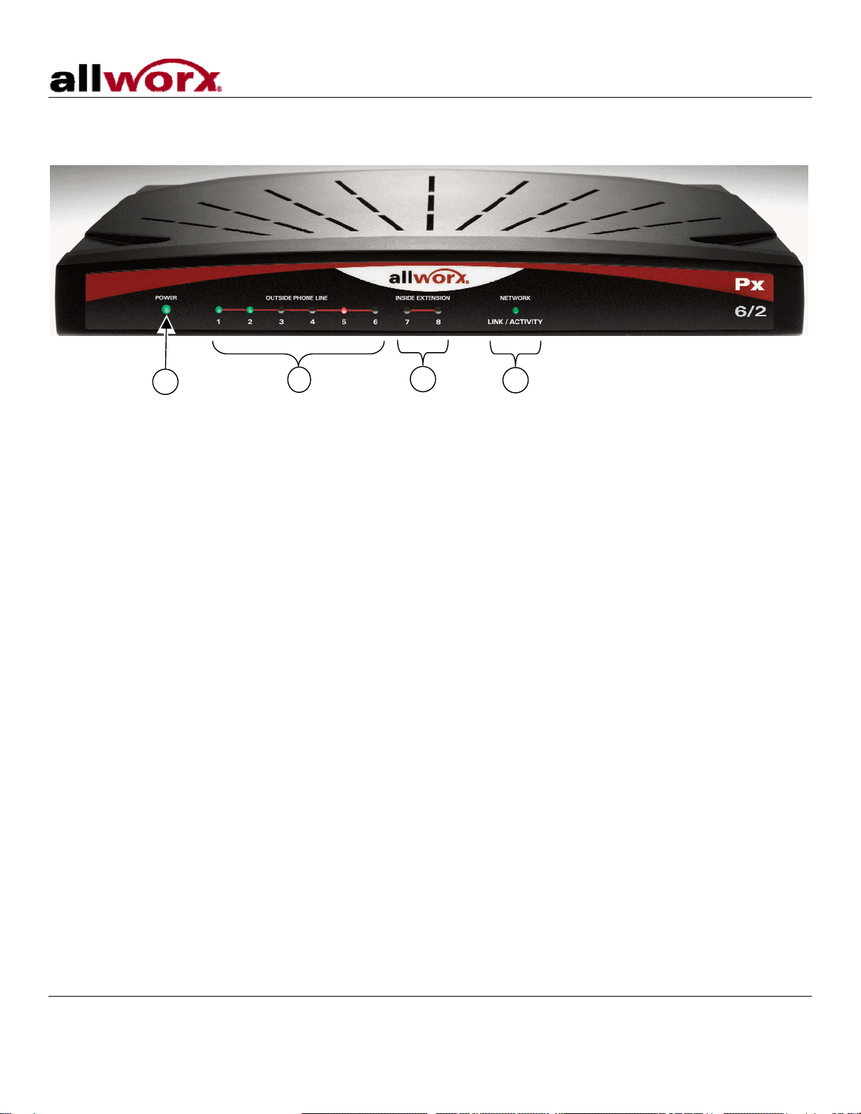
3Chassis Views...............................................................................................................................................4
4Mechanical....................................................................................................................................................6
4.1 Tabletop or Shelf Placement.......................................................................................................................6
4.2 Wall Mount..................................................................................................................................................6
5Electrical........................................................................................................................................................8
5.1 Chassis Ground ..........................................................................................................................................8
5.2 Power-Up Sequence...................................................................................................................................8
6Diagnostic Port..............................................................................................................................................9
7Port Expander Configuration.......................................................................................................................10
7.1 Configuring the Port Expander Password.................................................................................................10
7.2 Local Connection ......................................................................................................................................11
7.3 Remote Connection ..................................................................................................................................12
8Telephone Line Connection ........................................................................................................................14
9Data Network Connection ...........................................................................................................................15
10 Physical and Environmental Specifications.................................................................................................16
11 Regulatory Notices......................................................................................................................................17
11.1 FCC Part 68............................................................................................................................................17
11.2 Industry Canada......................................................................................................................................17
11.3 Radio and Television Interference ..........................................................................................................18
12 Wall Mount Template ..................................................................................................................................20

Px 6/2 Expander Installation Guide
300 Main Street • East Rochester, NY 14445 • Toll Free 1-866-ALLWORX • 585-421-3850 • www.allworx.com
© 2008 Allworx. All rights reserved
Version 03. Revised: May 16, 2008
Page 1
1 Installation Overview
Note: Use of the Allworx Px 6/2 Expander requires connection to an Allworx 6x, 10x, or 24x server. The server
must be equipped with the Internet Call Access Feature Key. Procure the key before beginning installation at
the customer site. Steps for procuring the key are included in Section 2, Procuring and Installing the Internet
Call Access Feature Key.
Installation of the Allworx Px 6/2 Expander involves the following steps:
1. Procurement and Installation of Internet Call Access Feature Key on Allworx server.
2. Unpacking
3. Mechanical Installation
4. Electrical Installation
5. Port Expander Configuration
6. Telephone Line Connection
7. Network Connection
Each of these steps will be described in the following sections.

Px 6/2 Expander Installation Guide
300 Main Street • East Rochester, NY 14445 • Toll Free 1-866-ALLWORX • 585-421-3850 • www.allworx.com
© 2008 Allworx. All rights reserved
Version 03. Revised: May 16, 2008
Page 2
2 Procuring and Installing the Internet Call Access Feature Key
Note: Use of the Allworx Px 6/2 Expander requires connection to an Allworx 6x, 10x, or 24x server. The server
must be running Release 6.9 and must have the Internet Call Access Feature Key installed. Obtain the key
using the following procedure:
1. Update the server to Release 6.9, if it has not already been upgraded.
Request must include:
• Name of requestor
• Name of Company
• Phone number
• Email address
• Px 6/2 Expander serial number
• Associated server serial number (e.g. 6x)
3. Once Customer Care validates the request, the key will be sent to the requestor (and to any additional e-
mail address provided by the requestor) with the key information.
4. If the server has access to the Internet, on the server Admin Maintenance / Feature Keys page, click the
Install button. If the server does not have access to the Internet, copy and past the key into the Key field on
the server Admin Maintenance / Feature Keys page.

Px 6/2 Expander Installation Guide
300 Main Street • East Rochester, NY 14445 • Toll Free 1-866-ALLWORX • 585-421-3850 • www.allworx.com
© 2008 Allworx. All rights reserved
Version 03. Revised: May 16, 2008
Page 3
Unpacking
Open the box and carefully unpack it. Save all shipping and packaging materials. Verify all items against the
parts list shown in Table 1. If any items are missing, contact your dealer or Allworx Customer Support at 866-
255-9679.
Quantity Item
1 Allworx Px 6/2 Port Expander
1 Power Adapter (12 VDC @ 1A)
1 Px 6/2 Port Expander Installation Guide
1 Sheet of 4 Rubber Feet
Table 1: Parts List

Px 6/2 Expander Installation Guide
3 Chassis Views Figure 1: Front Chassis View
300 Main Street • East Rochester, NY 14445 • Toll Free 1-866-ALLWORX • 585-421-3850 • www.allworx.com
© 2008 Allworx. All rights reserved
Version 03. Revised: May 16, 2008
Page 4
1 Power LED – Indicates system start-up activity
2 Outside Analog Phone Line LEDs – Indicates status of a particular FXO port
3 Inside Analog Extension LEDs – Indicates status of a particular FXS port
4 Network LED – Indicates Ethernet link status; flashes for activity
3
2 4
1

Px 6/2 Expander Installation Guide
Figure 2: Rear Chassis View
300 Main Street • East Rochester, NY 14445 • Toll Free 1-866-ALLWORX • 585-421-3850 • www.allworx.com
© 2008 Allworx. All rights reserved
Version 03. Revised: May 16, 2008
Page 5
5 Diagnostic port
6 RJ-45 10BaseT/100BaseTX Auto-Sensing Auto-MDI/MDIX Ethernet port.
7 RJ-11 FXS ports for inside extensions (Ports 7-8)
8 RJ-11 loop-start FXO for central office connection (Ports 1-6)
9 RJ-11 Power Fail analog phone connector
10 Ground connecting screw
11 5.5 x 2.1 mm power jack. Input 12 VDC @ 1A, center positive
7 85
6
9
1
0
11

Px 6/2 Expander Installation Guide
300 Main Street • East Rochester, NY 14445 • Toll Free 1-866-ALLWORX • 585-421-3850 • www.allworx.com
© 2008 Allworx. All rights reserved
Version 03. Revised: May 16, 2008
Page 6
4 Mechanical
4.1 Tabletop or Shelf Placement
To install the Allworx Px 6/2 on a tabletop or shelf:
1. Remove the four rubber feet from the packaging.
5. Turn over the chassis and notice the triangle on each corner (2 large triangles in front, 2 smaller in back).
6. Remove the paper backing from each rubber foot and place one foot in each triangle.
4.2 Wall Mount
To mount the Allworx Px 6/2 on ½” drywall:
1. Verify that there is sufficient clearance around the Port Expander’s front and rear panels to allow power,
network, and telephony connections.
2. Use self-drilling drywall anchors rated for at least 20 lbs with screws that are either #6 or #8. Locate two
anchors that will support the upper end of the unit using the template included in Section 12, Wall Mount
Template. Install the anchors per the anchor manufacturer’s recommendation. Install the mounting screws
into the anchors leaving approximately 1/8” between the bottom of the screw head and the wall.
3. Slide unit onto mounting screws. Adjust screw height if necessary to insure a snug fit against the wall.
Caution: The Allworx Port Expander must be securely mounted to the wall to avoid equipment
damage or personal injury.
Note: The unit must be mounted with the front facing forward, not up or down (see Figure 3).

Px 6/2 Expander Installation Guide
Figure 3: Wall Mount Orientation
300 Main Street • East Rochester, NY 14445 • Toll Free 1-866-ALLWORX • 585-421-3850 • www.allworx.com
© 2008 Allworx. All rights reserved
Version 03. Revised: May 16, 2008
Page 7
Correct Orientation Wrong Orientation

Px 6/2 Expander Installation Guide
300 Main Street • East Rochester, NY 14445 • Toll Free 1-866-ALLWORX • 585-421-3850 • www.allworx.com
© 2008 Allworx. All rights reserved
Version 03. Revised: May 16, 2008
Page 8
5 Electrical
5.1 Chassis Ground
Warning: Failure to follow these steps may result in equipment damage, personal injury, and void the
product warranty.
To help prevent electrical shock, the separate, protective earthing terminal located next to the power jack on
the rear panel (See Figure 2 item 10) must be permanently connected to earth using 18 AWG wire or larger.
5.2 Power-Up Sequence
Connect the unit’s Network port to an Allworx server LAN. Then connect the AC power adapter. The Port
Expander will automatically begin to power up. As it progresses through the power up sequence, the front
panel Power LED will flash green. If a network connection has been made and when the unit is ready, the
Power LED will shine steady green.
If no network connection has been made prior to when the unit is powered on, the Power LED will change from
flashing green to solid amber. Solid amber indicates that the unit is in Configuration Mode.

Px 6/2 Expander Installation Guide
300 Main Street • East Rochester, NY 14445 • Toll Free 1-866-ALLWORX • 585-421-3850 • www.allworx.com
© 2008 Allworx. All rights reserved
Version 03. Revised: May 16, 2008
Page 9
6 Diagnostic Port
The Diagnostic connector (See Figure 2, Item 5) is a serial port. Should Allworx Customer Support instruct you
to capture diagnostic data, connect a null modem serial cable from the Diagnostic connector to the serial port
on a PC. Configure the PC port in accordance with the following table:
Baud 9600
Data Bits 8
Parity None
Stop Bits 1
Flow Control None
Table 2: Serial Port Configuration

Px 6/2 Expander Installation Guide
7 Port Expander Configuration
Much like an Allworx phone, the Port Expander gets its configuration information and software updates from
the Allworx server. Therefore, the Network port of the Allworx Px 6/2 must be attached either directly or
remotely to an Allworx server. This is usually done by connecting to the server LAN through a network switch. .
Up to three Port Expanders can be connected to a given server. The diagram below depicts three Port
Expanders connected on a server LAN. When connected this way, the Port Expanders require no manual
configuration steps.
Figure 4, Connection Diagram
7.1 Configuring the Port Expander Password
Although connecting the Port Expander normally does not require any manual configuration, the need to
configure the Port Expander’s settings may arise in the future. Such situations can be made more convenient
by setting the Port Expander’s password during installation.
For security reasons, Allworx Px 6/2 Port Expanders do not have a default password. A site-specific password
must be created and entered using the Port Expander’s Configuration web page. Do this using the following
procedure:
1. If the Port Expander has already been powered on, disconnect power.
2. If a cable is plugged into the Network port, disconnect it.
3. Set up the PC’s network interface to obtain an IP address automatically (using DHCP).
4. Apply power to the Port Expander.
5. Wait until the power and port LEDs light solid amber (about 45 seconds). Connect the PC’s network port to
the Port Expander’s Network port with a standard RJ-45 category 5 Ethernet cable.
300 Main Street • East Rochester, NY 14445 • Toll Free 1-866-ALLWORX • 585-421-3850 • www.allworx.com
© 2008 Allworx. All rights reserved
Version 03. Revised: May 16, 2008
Page 10

Px 6/2 Expander Installation Guide
300 Main Street • East Rochester, NY 14445 • Toll Free 1-866-ALLWORX • 585-421-3850 • www.allworx.com
© 2008 Allworx. All rights reserved
Version 03. Revised: May 16, 2008
Page 11
6. Verify that the PC has an IP address on the 192.168.2.xxx network.
You may need to release and renew the PC’s IP address using the ipconfig command in a command
window to get an address from the Port Expander.
7. Open a web browser on the PC and enter http://192.168.2.254 into the browser’s address field.
The Port Expander’s Configuration screen is displayed.
8. Scroll to the New Password field. Enter the site’s new Port Expander administrator password. Re-enter the
password in the Confirm Password field.
9. Click Update
The Port Expander’s Update Result screen is displayed.
10. Disconnect the network cable from the Port Expander’s Network port. Connect the Port Expander to the
system using the procedure in either Section 7.2, Local Connection or Section 7.3, Remote Connection.
11. Save the password for future reference. If the password is lost or forgotten, it can be reset by repeating this
procedure and entering a new password.
7.2 Local Connection
When properly connected to the server LAN, the Allworx Px 6/2 will be configured automatically. This should
require no manual steps, although it is recommended that the password be set in accordance with the
procedure, above. To ensure the automatic configuration is successful, perform the following steps:
1. If the Port Expander has already been powered on, disconnect power.
2. Connect the Network port of the Port Expander to the LAN of the Allworx server per the diagram above
using a standard RJ-45 category 5 Ethernet cable.
3. Apply power to the Port Expander.
4. Observe the Power LED. During power up, it will flash green. When the LED stops flashing and shines
solid green, the Port Expander has received any software updates and has been configured. This may take
as long as five (5) minutes. It is now ready for CO lines and analog phones to be connected to its FXO and
FXS ports.
5. If the Power LED does not shine solid green within five (5) minutes. Unplug and re-plug the Port
Expander’s power adapter.
6. Activate the FXO and FXS ports through the Web Admin page on the Allworx Server. Refer to the Allworx
System Administrator’s Guide, Release 6.9 or higher for information on configuring the ports.

Px 6/2 Expander Installation Guide
300 Main Street • East Rochester, NY 14445 • Toll Free 1-866-ALLWORX • 585-421-3850 • www.allworx.com
© 2008 Allworx. All rights reserved
Version 03. Revised: May 16, 2008
Page 12
7.3 Remote Connection
Allworx Px 6/2 Port Expanders can be configured to run at sites that are remote to the Allworx server. Much
like with a remote Allworx phone, this requires manual configuration of the Port Expander. The Boot Server IP
(the Allworx Server’s IP) and the server’s Plug and Play Secret Key must be entered within the Port
Expander’s configuration interface. In addition, forwarding of ports through intervening firewalls may be
required. See the Allworx System Administrator’s Guide, Release 6.9 for instructions for configuring firewalls.
Caution: Correct routing of 911 emergency calls for analog handsets attached to remote Allworx Port
Expanders cannot be guaranteed. Do not use the Px’s FXS ports for handsets from which
placing 911 calls may be attempted.
Caution: If the network connection between the Port Expander and the Allworx server is interrupted,
regular use of the Port Expander’s FXO and FXS ports will not be possible. The only option
for placing calls through a Port Expander that does not have a functional network
connection to its Allworx server is to plug an analog phone into the Power Fail port. Calls
placed using this phone will be routed to the CO line connected to FXO port 1. No other
ports will be functional.
To configure the Boot Server IP and Plug and Play Secret Key, perform the following steps:
1. Access the Port Expander’s Configuration screen by performing Steps 1 through 7 of the procedure in
Section 7.1, Configuring the Port Expander Password.
2. Navigate to the Boot Server IP Address field. Enter the IP address of the Allworx Server to which the Port
Expander will be associated.
3. Navigate to the Plug and Play Secret Key field. Enter the Allworx Server’s Secret Key. To determine the
server’s Secret Key, see the Allworx System Administrator’s Guide, Release 6.9 for instructions.
4. Re-enter the key in the Confirm Plug and Play Secret Key field.
5. If the Port Expander’s administrator password has not been set, scroll to the New Password field. Create a
site-specific password and enter it into the New Password field. Re-enter the password in the Confirm
Password field.
6. Click Update
The Port Expander’s Update Result screen is displayed.
7. Click Restart
8. Connect the Network port of the Port Expander to the site’s network using a standard RJ-45 category 5
Ethernet cable.
Note: A network path to the Allworx Server must be available.
9. Observe the Power LED. During power up, it will flash green. When the LED stops flashing and shines
solid green, the Port Expander has received any software updates, and has been fully configured. This

Px 6/2 Expander Installation Guide
300 Main Street • East Rochester, NY 14445 • Toll Free 1-866-ALLWORX • 585-421-3850 • www.allworx.com
© 2008 Allworx. All rights reserved
Version 03. Revised: May 16, 2008
Page 13
may take as long as five (5) minutes. It is now ready for CO lines and analog phones to be connected to its
FXO and FXS ports.
10. If the Power LED does not shine solid green within five (5) minutes. Unplug and re-plug the Port
Expander’s power adapter.
11. If you have entered a new password, save it for future reference. If the password is lost or forgotten, it can
be reset by repeating the procedure in Section 7.1, Configuring the Port Expander Password and entering
a new password.
12. Activate the FXO and FXS ports through the Web Admin page on the Allworx Server. Refer to the Allworx
System Administrator’s Guide for Release 6.9 or higher for information on configuring the ports.

Px 6/2 Expander Installation Guide
300 Main Street • East Rochester, NY 14445 • Toll Free 1-866-ALLWORX • 585-421-3850 • www.allworx.com
© 2008 Allworx. All rights reserved
Version 03. Revised: May 16, 2008
Page 14
8 Telephone Line Connection
Caution: To reduce the risk of fire, use only 26 AWG (or larger) UL listed or CSA certified
telecommunications line cord.
The Port Expander’s analog phone connections can be used to connect Central Office (CO) lines or telephone
handsets. The following table describes the ports:
RJ-11 Ports Type Description
1-6 FXO (loop-start) Used to connect to Central Office (CO) lines
7-8 FXS Analog telephone handsets
Table 3: Analog Telephony Ports
It is recommended that the ports be connected as follows:
• CO Lines: Begin with port 1 and move up.
• Telephone Handsets: Begin with port 8 and move down.
The Power Fail Phone port may be used to connect an analog phone device that is operational in the event
that the Port Expander loses power, if it loses its network connection to the Allworx server, or if some other
hardware failure occurs. When in this condition, calls using an analog phone connected to the Power Fail
Phone port will be routed to the first outside phone line port (port 1).
Surge protection is provided internally on all telephony interfaces.
Under normal operation of the unit, the port LEDs will appear as listed, below.
Port LED Indicator Port (1-8) State
Off Normal Idle
Green Solid Off Hook
Green Fast Blink Ringing
Alternating Red/Amber No loop current detected on last off
hook attempt (FXO only)
Table 4: Analog Port LED Definitions

Px 6/2 Expander Installation Guide
300 Main Street • East Rochester, NY 14445 • Toll Free 1-866-ALLWORX • 585-421-3850 • www.allworx.com
© 2008 Allworx. All rights reserved
Version 03. Revised: May 16, 2008
Page 15
9 Data Network Connection
The Network port is 10BaseT/100BaseTX auto-sensing and auto-MDI/MDIX port.
Once the Port Expander is powered up and in normal mode, the Network LED indicates the state of the
Network link, as shown below.
Color State Description
Off No link: the network is not connected
On Link: the network is successfully connected
Green Blinking Activity: data is being transmitted or received
Table 5: Network Port LED Definitions

Px 6/2 Expander Installation Guide
300 Main Street • East Rochester, NY 14445 • Toll Free 1-866-ALLWORX • 585-421-3850 • www.allworx.com
© 2008 Allworx. All rights reserved
Version 03. Revised: May 16, 2008
Page 16
10 Physical and Environmental Specifications
Dimensions (W x H x D) 12.1 x 1.9 x 7.6 inches (30.8 x 4.8 x 19.3 cm)
Weight (Base Model) 3 lbs
Power DC 12V, 1 Amp.
Temperature 0°~ 40°C
Humidity 15%~ 90%RH, Non-condensing
Table 6: Physical and Environmental Specifications

Px 6/2 Expander Installation Guide
300 Main Street • East Rochester, NY 14445 • Toll Free 1-866-ALLWORX • 585-421-3850 • www.allworx.com
© 2008 Allworx. All rights reserved
Version 03. Revised: May 16, 2008
Page 17
11 Regulatory Notices
11.1 FCC Part 68
This equipment complies with Part 68 of FCC rules and the requirements adopted by ACTA. On the backside
of this equipment is a label that contains, among other information, a product identifier in the format US:
AAAEQ##TXXXX. If requested, provide this number to the telephone company.
A plug and jack used to connect this equipment to the premises wiring and telephone network must comply
with the applicable FCC Part 68 rules and requirements adopted by the ACTA. See installation instructions for
details.
The REN is used to determine the number of devices that may be connected to a telephone line. Excessive
RENs on a telephone line may result in the devices not ringing in response to an incoming call. In most but not
all areas, the sum of RENs should not exceed five (5.0). To be certain of the number of devices that may be
connected to a line, as determined by the total RENs, contact the local telephone company. For products
approved after July 23, 2001, the REN for this product is part of the product identifier that has the format
US:AAAEQ##TXXXX. The digits represented by ## are the REN without a decimal point (e.g., 03 is a REN of
0.3). For earlier products, the REN is separately shown on the label.
If this equipment causes harm to the telephone network, the telephone company will notify you in advance that
temporary discontinuance of service may be required. But if advance notice isn't practical, the telephone
company will notify the customer as soon as possible. Also, you will be advised of your right to file a complaint
with the FCC if you believe it is necessary.
The telephone company may make changes in its facilities, equipment, operations or procedures that could
affect the operation of the equipment. If this happens, the telephone company will provide advance notice in
order for you to make necessary modifications to maintain uninterrupted service.
If trouble is experienced with this equipment, for repair or warranty information, please contact our company. If
the equipment is causing harm to the telephone network, the telephone company may request that you
disconnect the equipment until the problem is resolved.
11.2 Industry Canada
The Industry Canada label identifies certified equipment. This certification means that the equipment meets
telecommunications network protective, operation and safety requirements as prescribed in the appropriate
Terminal Equipment Technical Requirements document(s). The Department does not guarantee the
equipment will operate to the user's satisfaction. Before installing this equipment, users should ensure that it is
permissible to be connected to the facilities of the local telecommunications company. The equipment must
also be installed using and acceptable method of connection. The customer should be aware that compliance
with the above conditions might not prevent degradation of service in some situations.
Repairs to certified equipment should be coordinated by a representative designated by the supplier. Any
repairs or alterations made by the user to this equipment, or equipment malfunctions, may give the
telecommunications company cause to request the user to disconnect the equipment.
Other manuals for Px 6/2
1
Table of contents
Other Allworx Extender manuals
Popular Extender manuals by other brands

Stuart Turner
Stuart Turner Mainboost MB 100SV Installation, operation & maintenance instructions

Metra Electronics
Metra Electronics CS-HDC5EXTS user manual

Eaton
Eaton TRIPP LITE Series installation instructions

Philips
Philips SRU4000/17 Code List

Foxun
Foxun SX-EX11 operating instructions

EnGenius
EnGenius ERB9250 quick guide

Cooper Wheelock
Cooper Wheelock Series SPB Installation, testing, operation and maintenance manual

NetComm
NetComm NP560 Specifications

Honeywell
Honeywell CBU146 instructions

Teletics
Teletics ZipLine Quick start installation manual

Playvision
Playvision HDV-E50S2 user manual

dji
dji Ronin 4D Video Transmitter user guide