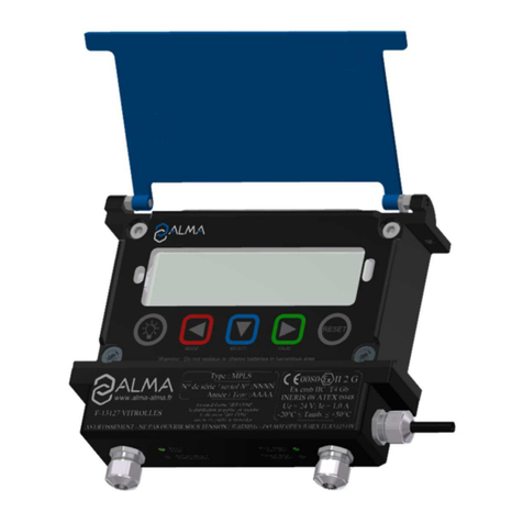
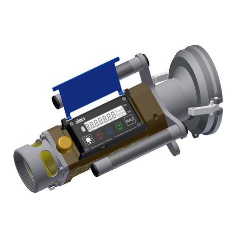
Almaco DUAL TRONIQUE User manual

FORM DOC 120 A
MU 7093 EN C
DUAL TRONIQUE
Page 1/69
This document is available on www.alma-alma.fr
USER MANUAL
MU 7093 EN C
DUAL TRONIQUE
C
2021/12/22
Evolution of the measuring system menu. Control of
a reel. Blocking contamination and DSPGI. Viscosity
correction %. Presence of a trailer. Import ICOM
settings onto SD card Number of additive injectors in
metrological mode. RCT5 remote control
DSM
FDS
Issue
Date
Nature of modifications
Written by
Approved by
Document applicable for software from version 4053+v1.7.x and 446v1.1.x

FORM DOC 120 A
MU 7093 EN C
DUAL TRONIQUE
Page 2/69
This document is available on www.alma-alma.fr
CONTENTS
1GENERAL PRESENTATION AND DESCRIPTION..................................................................................5
2CONNECTED FEATURES..................................................................................................................7
3CONFIGURATION, SETTINGS, CALIBRATION ....................................................................................9
4SPECIFIC FEATURES........................................................................................................................9
4.1 Use with DSPGI device...........................................................................................................9
4.2 Contamination control on both full hoses ............................................................................ 10
4.3 Distribution mode PRESET+PURGE....................................................................................... 10
5USE THE DUAL TRONIQUE: USER MODE ....................................................................................... 11
5.1 Menu DELIVERY................................................................................................................... 11
5.1.1 Pumped counted distribution mode ........................................................................................................13
5.1.1.1 Delivery...........................................................................................................................................13
5.1.1.2 Two step purge ...............................................................................................................................16
5.1.2 Pumped not counted distribution mode..................................................................................................18
5.1.2.1 Delivery...........................................................................................................................................18
5.1.3 Intermediate stop of the delivery ............................................................................................................19
5.1.4 Gravity delivery ........................................................................................................................................20
5.2 Menu PRODUCT MOVEMENTS............................................................................................. 21
5.2.1 Sub-menu HOSE PURGE ...........................................................................................................................21
5.2.2 Sub-menu PRODUCT TRANSFER...............................................................................................................22
5.2.3 Sub-menu PRODUCT LOADING ................................................................................................................22
5.3 Menu LOADING PLAN.......................................................................................................... 23
5.4 Menu PRINT........................................................................................................................ 24
5.5 Menu DISPLAY .................................................................................................................... 26
5.5.1 Sub-menu TOTALISER(S)...........................................................................................................................26
5.5.2 Sub-menu MEMORY.................................................................................................................................26
5.6 Menu MAINTENANCE.......................................................................................................... 27
5.6.1 Sub-menu COMPUTING ...........................................................................................................................27
5.6.2 Sub-menu DSPGI ......................................................................................................................................27
5.6.3 Sub-menu CONTAMINATION ...................................................................................................................28
5.6.4 Sub-menu SOFTWARE ..............................................................................................................................28
5.6.5 Sub-menu BATTERY VOLTAGE..................................................................................................................28
5.6.6 Sub-menu HYDRAULIC..............................................................................................................................28
5.6.7 Sub-menu TEMPERATURES ......................................................................................................................28
5.6.8 Sub-menu INPUTS ....................................................................................................................................29
5.6.9 Sub-menu OUTPUTS.................................................................................................................................30
5.7 List of alarms....................................................................................................................... 31

FORM DOC 120 A
MU 7093 EN C
DUAL TRONIQUE
Page 3/69
This document is available on www.alma-alma.fr
6SET THE DUAL TRONIQUE: SUPERVISOR MODE............................................................................. 33
6.1 Menu CALIBRATION/ GAUGE............................................................................................... 33
6.1.1 Pumped mode ..........................................................................................................................................33
6.1.1.1 Sub-menu ENTER STANDARD VALUE..............................................................................................33
6.1.1.2 Sub-menu LINEARISATION/FLOW...................................................................................................34
6.1.2 Gravity mode............................................................................................................................................35
6.2 Menu PRODUCT SETTINGS................................................................................................... 35
6.3 Menu CONFIGURATION....................................................................................................... 37
6.3.1 Sub-menu ID LINES...................................................................................................................................37
6.3.2 Sub-menu EM SETTINGS –Not applicable ...............................................................................................37
6.3.3 Sub-menu VEHICLE...................................................................................................................................37
6.3.4 Sub-menu CURRENCY...............................................................................................................................37
6.3.5 Sub-menu LOADING PLAN........................................................................................................................37
6.3.6 Sub-menu ADDITIVE TYPE ........................................................................................................................38
6.3.7 Sub-menu REMOTE CONTROL..................................................................................................................38
6.4 Menu SETTINGS .................................................................................................................. 39
6.4.1 Sub-menu VOLUME or MASS SETTINGS...................................................................................................39
6.4.2 Sub-menu FLOWRATE SETTINGS..............................................................................................................40
6.4.3 Sub-menu TIMING SETTINGS ...................................................................................................................40
6.4.4 Sub-menu BACKUP VALUES......................................................................................................................41
6.5 Menu TIME ADJUSTMENT.................................................................................................... 41
6.6 Menu PRINTER SETTINGS..................................................................................................... 41
6.7 Menu DSPGI........................................................................................................................ 42
6.8 Menu COMPUTING.............................................................................................................. 43
6.9 Menu LANGUAGE................................................................................................................ 43
6.10 Menu ICOM MENUS ............................................................................................................ 43
7CONFIGURE THE DUAL TRONIQUE: METROLOGICAL MODE........................................................... 45
7.1 Menu INDICATOR REFERENCE.............................................................................................. 45
7.2 Menu CONFIGURATION....................................................................................................... 45
7.2.1 Sub-menu DUAL OPTION..........................................................................................................................45
7.2.1.1 DUAL OPTION NOT ENABLED .........................................................................................................46
7.2.1.2 DUAL OPTION ENABLED .................................................................................................................46
7.2.2 Sub-menu INSTRUMENTATION................................................................................................................47
7.2.2.1 PTO .................................................................................................................................................47
7.2.2.2 OVERFILL PREVENTION ...................................................................................................................47
7.2.2.3 ADDITIVE INJECTOR ........................................................................................................................48
7.2.2.4 PUMPED NOT COUNTED.................................................................................................................48
7.2.3 Sub-menu COMPARTMENT OPTIONS ......................................................................................................48
7.2.4 Sub-menu OPTION CMA –Not applicable................................................................................................49
7.2.5 Sub-menu HYDRAULIC –Not applicable ..................................................................................................49

FORM DOC 120 A
MU 7093 EN C
DUAL TRONIQUE
Page 4/69
This document is available on www.alma-alma.fr
7.2.6 Sub-menu UNIT ........................................................................................................................................49
7.2.7 Sub-menu CONVERSION ..........................................................................................................................50
7.3 Menu measuring system EMA ............................................................................................. 50
7.3.1 Sub-menu METER COEFFICIENT ...............................................................................................................50
7.3.2 Sub-menu VISCOSITY CORRECTION .........................................................................................................51
7.3.3 Sub-menu UNIT ........................................................................................................................................51
7.3.4 Sub-menu METER FLOWRATES ................................................................................................................52
7.3.5 Sub-menu QUANTITIES ............................................................................................................................52
7.3.6 Sub-menu TEMPERATURE ........................................................................................................................53
7.3.7 Sous-menu FORMULA ..............................................................................................................................53
7.3.8 Sub-menu DETECTORS .............................................................................................................................54
7.3.9 Sub-menu VALVE......................................................................................................................................54
7.4 Menu measuring system EMB.............................................................................................. 54
7.5 Menu DATE AND TIME......................................................................................................... 55
ANNEX 1: Presentation of the menu SUPERVISOR>ICOM MENUS .......................................................... 56
ANNEX 2: Visualization of the permitted characters on the MICROCOMPT+ display:.............................. 64
ANNEX 3: Assignments table according to the number of flaps, product returns and additive injectors .. 65
ANNEX 4: Printings.............................................................................................................................. 66
RELATED DOCUMENTS......................................................................................................................... 69

FORM DOC 120 A
MU 7093 EN C
DUAL TRONIQUE
Page 5/69
This document is available on www.alma-alma.fr
1 GENERAL PRESENTATION AND DESCRIPTION
The DUAL TRONIQUE is a system that can manage one or two measuring systems based on a
single calculator-indicator MICROCOMPT+.
These measuring systems are fitted on a road tanker. It measures liquids other than water either
by gravity or by pumping.
When the system manages a single measuring system, it is called EMA.
When the system manages two measuring systems, they are called EMA and EMB.
The measuring systems are:
Certified type (see the relevant EC-type or EU-type examination certificate)
Of same model or of different models
The DUAL TRONIQUE comprises at least:
Presentation of the MICROCOMPT+ mono or dual:
One or two measuring systems
A set of delivery hose(s) that depends on the measuring system
It performs the following functions:
Measure products when they are delivered to the station, with or without volume preset
Split compartments
Control the product movements (transfer, loading, return, purge, draining)
Depending on the hydraulic configuration, the system can manage one or two distribution ways:
On EMA: One distribution way full hose or empty hose or two distribution ways: hose 1 and 2
On EMB: One distribution way full hose or empty hose
If the feature is enabled a delivery channel is available for pumped not counted distribution.
According to hardware configuration, it controls up to nine compartments. You can configure 16
different products.
It can be connected to DSPGI anti-contamination systems. DSPGI devices provide product
identification for each compartment and update the MICROCOMPT+. This eliminates any mixture
of product. Each compartment is equipped with a DSPGI.
The system can control one or two additive injection devices. This injection has to occur upstream
the meter.
In option, the system controls the product temperature.
In addition, it may be connected to a printer for delivery tickets, internal totalisers, parameters or
diary printings.
NOTE: The information printed by the printer has no metrological value. Only the indications
displayed by the indicator shall be considered legally valid.

FORM DOC 120 A
MU 7093 EN C
DUAL TRONIQUE
Page 6/69
This document is available on www.alma-alma.fr
The MICROCOMPT+ has one display:
The displayed quantity depends on the system configuration. The user is informed by a pictogram
at the top-right of the display according to the conventions below:
Volume in metering conditions: pictogram Vm
Volume converted to the reference temperature: pictogram Vb
Mass: no pictogram
Vm
L Kg/m3
/min /h
536
ADDITIONAL INFORMATION EmA
Configured data are pre-visualized thanks to menus. In the example above, XX corresponds to the
value given to the conversion, either OFF or ON.
CONVERSION (XX)CONVERSIONOFF
CONVERSIONON
The MICROCOMPT+ has three pushbuttons:
Increment a blinking figure or letter
Come back to the previous step
Stop the measurement
Specific case: automatic scheduling (see §4.2)
Select a figure, a letter or a menu
Specific case: automatic scheduling (see §4.2)
Validate the data
Specific case: automatic scheduling (see §4.2)
Quantity
Pictogram: Vm, Vb or none
Unit of the displayed quantity
Measuring system in operation
On the prompter: Additional information
- During measurement: delivery mode, compartment,
and product
- Out of measurement: name of menus

FORM DOC 120 A
MU 7093 EN C
DUAL TRONIQUE
Page 7/69
This document is available on www.alma-alma.fr
Use the RFID keys:
Blue key: Level-User
This key is associated to a single MICROCOMPT+.
It is used to switch into SUPERVISOR mode
Green key: Level-Manager
Many of these keys can be associated to a single MICROCOMPT+.
Likewise, a single key can be associated to one or many
MICROCOMPT+.
RFID key is used to switch into SUPERVISOR mode. Specific menus are
available that allow the manager to configure the MICROCOMPT+ for its
communication with the external environment. The specific menus are
indicated by green boxes within the ANNEX 1.
Red key: Level-Maintenance
This key doesn’t need to be associated to the MICROCOMPT+. It is used
to switch into SUPERVISOR mode. Specific menus are available that
allow the maintenance operator to change parameters. Those menus are
indicated in red boxes
2 CONNECTED FEATURES
The wireless connection enables the MICROCOMPT+ to communicate with an embedded
computer or with a PC/tablet/portable device, in hazardous area (ATEX).
The connected functions of the MICROCOMPT+ are the following:
Incoming data flow processing
Management of the communication modules below
Communication modules are listed below:
Wi-Fi (IEEE 802.11 b/g/n (2.4GHz) OR Bluetooth Low Energy 4.1
GSM (2G, 3G, 4G) / GPS
RFID NFC allowing the reading of an RFID key to switch in SUPERVISOR mode
Ethernet Base 10/100
The GSM module associated to the GPS navigation system allows the device tracking. Two
antennas are located outside the MICROCOMPT box.

FORM DOC 120 A
MU 7093 EN C
DUAL TRONIQUE
Page 8/69
This document is available on www.alma-alma.fr
Three tricolor LED on the MICROCOMPT+ front face are showing the wireless connection status
as described in the table below:
Left-hand LED:
Bluetooth or Wi-Fi
Middle LED:
GSM / GPS
Right-hand LED:
NFC (RFID)
Steady light
Bluetooth
Wi-Fi
Connection OK
Waiting for
internet
connection
Internet
connection
OK
Waiting for
initialization
Waiting for
initialization
Flashing light
Bluetooth
Wi-Fi
Slow flashing:
Waiting for
connection
every 2
seconds
GPS OK
Authentication of
the RFID key OK
Bluetooth
Wi-Fi
Rapid flashing:
Communication
in progress
Transfer in
progress
RFID key not
accepted, but
authentication is
ok
every 2
seconds
Coordinates
not found
Initialization
error
Initialization
error
Authentication
error of the RFID
key

FORM DOC 120 A
MU 7093 EN C
DUAL TRONIQUE
Page 9/69
This document is available on www.alma-alma.fr
3 CONFIGURATION, SETTINGS, CALIBRATION
CONFIGURATION:
METROLOGICAL mode
SETTINGS:
SUPERVISOR mode
SETTINGS, CALIBRATION:
SUPERVISOR mode
§ CONFIGURE THE DUAL
TRONIQUE:
METROLOGICAL MODE
§ SET THE DUAL TRONIQUE:
SUPERVISOR MODE
§ANNEX 1
§ SET THE DUAL
TRONIQUE: SUPERVISOR
MODE
§ANNEX 1
You must configure the DUAL
TRONIQUE during
commissioning and sometimes
during metrological controls.
You must set the DUAL
TRONIQUE before any
operation and sometimes
during metrological controls
(specific menus)
You must set the DUAL
TRONIQUE before any
operation.
You must control the accuracy
of the DUAL TRONIQUE
cyclically
NOTE: Only approved persons
are permitted to remove the seal
NOTE: Only approved persons
are permitted to change
parameters of the specific
menus
NOTE: Only approved persons
are permitted to change
parameters or to make
calibration.
- Unseal the cup
- Remove the seal
- Put the RFID key
at the right side of the
display
- Put the RFID key
at the right side of the
display
4 SPECIFIC FEATURES
4.1 Use with DSPGI device
If compartments are equipped with DSPGI devices, the DSPGI code associated to the
product quality must be set (menu SUPERVISOR>PRODUCT SETTINGS>DSPGI CODE). A
specific menu also allows you to assign a DSPGI code to an empty compartment
(SUPERVISOR>DSPGI>EMPTY CODE).
Operation with DSPGI may or may not be blocking. If it is blocking, it is possible to suspend
the blocking for the current operation. See the menu SUPERVISOR>DSPGI that describes the
different features.

FORM DOC 120 A
MU 7093 EN C
DUAL TRONIQUE
Page 10/69
This document is available on www.alma-alma.fr
The name of the product that is supposed to be in the hose, is displayed in brackets at the
right hand of DELIVERY, for example: DELIVERY (GO+). The product’s name given by the
DSPGI device is also displayed at the compartment selection or a return.
In case of communication failure with the DSPGI device, depending on the configuration, you
can switch in manual mode without DSPGI. See the menu SUPERVISOR>DSPGI that
describes the different features.
The product’s name is replaced by warning messages in the following cases:
DSPGI DEFAULT: The DSPGI is ON and there is a communication problem
?????: The DSPGI is ON and its drum is located between two positions
DSPGI MISMATCH: Inconsistent data in loading plan and DSPGI (product or compartment)
The messages below are printed in the event log:
DSPGI ERROR: A DSPGI default has been recorded
DSPGI CONFLICT: When the product selected in degraded mode is different from the
product known by the DSPGI.
4.2 Contamination control on both full hoses
According to the nature of the products, the DUAL TRONIQUE calculates the purge volumes
in order to ensure a downgrading of the brewing areas in order to never contaminate the
noblest product.
The DUAL TRONIQUE memorizes permanently the quality in hose 1, hose 2, manifold and
the common pipe. It systematically displays the product contained in all these elements.
When the quality is not defined, in case of mixture for example, it displays the first product.
The DUAL TRONIQUE declares if a risk of contamination can occur. There’s a mismatch
between the selected product and the quality contained in the common pipe and the hose
selected for delivery. This alert does not prevent the product selection. However, if the
blocking contamination feature is activated CONTAMINATION>BLOCKING C.ON, this situation
requires a purge. It is possible to suspend the blocking for the current operation using the
menu MAINTENANCE>CONTAMINATION>WITHOUT (NOT BLOCKING).
4.3 Distribution mode PRESET+PURGE
The distribution mode PRESET+PURGE can include a step that forces to select the hose for
the next delivery. It is used to determine the volume of purge.
If the delivery has not been completed and if the purge has begun, you must complete the
purge before starting the next delivery (menu PRODUCT MOVEMENTS>HOSE PURGE).
The delivery mode PRESET + PURGE is not available:
If the DUAL TRONIQUE doesn’t control the compartment flap
In pumped not counted distribution mode

FORM DOC 120 A
MU 7093 EN C
DUAL TRONIQUE
Page 11/69
This document is available on www.alma-alma.fr
5 USE THE DUAL TRONIQUE: USER MODE
PRODUCT MOVEMENTS
LOADING PLAN
DELIVERY
ENGINE CONTROL
PRINT
DISPLAY
MAINTENANCE
With active option
With active option
The use of the DUAL TRONIQUE depends on the hardware configuration of the truck, the
features and the configuration of the equipment carried out during commissioning.
Therefore, the user menu depends on several items:
The instrumentation of the power take off.
The number of measuring systems (one or two)
The number of distribution ways (one or two)
The remote control
The number of compartments
The control of the compartments flaps
The control of the return product system (SRP)
The distribution mode (pumped counted, pumped not counted )
The temperature control (conversion of the volume).
5.1 Menu DELIVERY
There are several distribution modes:
PRESET: It allows to deliver a quantity of product previously entered. The delivery is
stopped automatically
PRESET+PURGE: It allows to deliver a quantity of product previously entered and the
purging of the hose. The delivery is stopped automatically
FREE: It allows to deliver a quantity of product in low or high flow. A user action is
required to stop the delivery.
At rest, the MICROCOMPT displays a flashing number and the product label corresponding to
the last quantity delivered.

FORM DOC 120 A
MU 7093 EN C
DUAL TRONIQUE
Page 12/69
This document is available on www.alma-alma.fr
During measurement, the following information may be displayed:
The instantaneous high or low flow rate. The unit depends on settings
The level of liquid in the compartment is use
The temperature (°C) if it is taken into account.
Simply follow the indications below:
With active option
INSTANT. TEMPERATURE
+12.3 °CKg /m3
/min /h
LIQUID HEIGHT
000749 Kg /mm
/min /h
INSTANT. HIGH FLOW
059,3 Kg /m3
/min /h
INSTANT. TEMPERATURE
LIQUID HEIGHT
INSTANTANEOUS FLOW
Change flowrate (HF/LF)
Unit: m3/h or L/min
Back to normal display is automatic: DO NOT PRESS RED CLEAR BUTTON TO KEEP
FROM INTERRUPTING DELIVERY.
Delivery can be performed in high or low flow. This choice is made for pumped deliveries at
the display of the message START HIGH FLOW. The blue MENU BUTTON switches on the
display START LOW FLOW. The choice is made by pressing the green OK BUTTON.
Switching is possible during the delivery by pressing the blue MENU BUTTON.
START HIGH FLOW
START LOW FLOW
NOTE: In the event of a delivery interruption, improper handling of the pushbuttons may enter
the menu DISPLAY (totalisers, memory). Simply press the red button to display DISPLAY and
then the blue button to return to DELIVERY STOP. Confirm with the green button to select the
next step (see § Finish/Continued delivery).

FORM DOC 120 A
MU 7093 EN C
DUAL TRONIQUE
Page 13/69
This document is available on www.alma-alma.fr
5.1.1 Pumped counted distribution mode
With active option, the commands for the pump clutching/declutching and for the power take-off control are made by the DUAL
TRONIQUE at the beginning and at the end of distribution.
ENGINE CONTROL ENGINESTART
ENGINESTOP Delivery
5.1.1.1Delivery
Choose
product
Choose
hose MODEPRESET
MODEPRESET+PURGE
MODEFREE
1
2
3
Choose
measuring
system
WAYPUMPED COUNTED HOSE
CONTAMINATION CONFIRM
CONTAMINATION?
Choosen product ≠Hose product
Non-systematic phases.

FORM DOC 120 A
MU 7093 EN C
DUAL TRONIQUE
Page 14/69
This document is available on www.alma-alma.fr
START
DELIVERY PRESET/ FUEL/CPT
ENTER PRESET
VOLUME
1ENGAGE
PTO
1
CPT WITH XXXX L
X
CPT WITH XXXX L
TRAILER DELIVERY
2
CPT WITH XXXX L
END
DELIVERY DELIVERY
FINISHED DELIVERY
TICKET
INVOICE
Print
PTO REMOVING
Choose
compartment START
DELIVERY
MOVE
VEHICLE DELIVERY
PAUSE Delivery
PTO REMOVING ENGAGE PTO
STOP
ENGINE? WIND THE HOSE? WINDING
Press and hold the green button to wind up the hose.
Press the red push button to go to the next step.
CONTINUE
DELIVERY START
DELIVERY 1ENTER PRESET
VOLUME
Intermediate stop
Non-systematic phases.

FORM DOC 120 A
MU 7093 EN C
DUAL TRONIQUE
Page 15/69
This document is available on www.alma-alma.fr
X
CPT WITH XXXX L
ENTER PRESET+PURGE PURGE WITHGO Choose purge
compartment
2
START
DELIVERY PRESET/ FUEL/CPT START PURGE PRESET/ FUEL/CPT
Choose
hose for
next delivery
ENGAGE
PTO
1
CPT WITH XXXX L
2
CPT WITH XXXX L
PURGE/ FUEL/CPT
Intermediate stop
END
DELIVERY
DELIVERY
FINISHED DELIVERY
TICKET
INVOICE
Print
PTO REMOVING STOP
ENGINE? WIND THE HOSE? WINDING
Press and hold the green button to wind up the hose.
Press the red push button to go to the next step.
START
DELIVERY FREE/FUEL/CPT
3ENGAGE
PTO
1
CPT WITH XXXX L
X
CPT WITH XXXX L
2
CPT WITH XXXX L
TRAILER DELIVERY
EMPTY COMPARTMENT NEXT CPT DELIVERY STOP
Intermediate stop
Non-systematic phases.

FORM DOC 120 A
MU 7093 EN C
DUAL TRONIQUE
Page 16/69
This document is available on www.alma-alma.fr
5.1.1.2Two step purge
Some delivery scenarios require a two-step purge.
SCENARIO 1: Both hoses and the common pipe are filled with FOD. For the next delivery, we want to deliver FOD+ with hose 2.
30 L
VOLUME OF PURGE 2 STEP PURGE 30 L
START PURGE 12 L
PURGE / FOD+ / CPT2 30 L
END PURGE 30 L
BLOWING 30 L
PURGE FINISHED 30 L
DELIVERYTICKET
HOSE PURGE PRODUCTFOD+
630 L
PRODUCT MOVEMENTS
630 L
DELIVERY( FOD)
HOSE 1
HOSE 2
Choose
return Choose
compartment NEXTHOSE 1
NEXTHOSE 2
30 L
ENGINECONTROL 30 L
DELIVERY( FOD+)
Second step: Purge hose 2 and common pipe with menu DELIVERY
2ND STEP HOSE F2 HOSE PURGE
30 L
DELIVERY( FOD+) 66 L
VOLUME OF PURGE
66 L
START PURGE 38 L
PURGE / FOD+ / CPT2 66 L
END PURGE 66 L
BLOWING 66 L
PURGE FINISHED 66 L
DELIVERYTICKET Delivery
Choose
return Choose
compartment
66 L
STOPENGINE?
Non-systematic phases.

FORM DOC 120 A
MU 7093 EN C
DUAL TRONIQUE
Page 17/69
This document is available on www.alma-alma.fr
SCENARIO 2: Hose 1 is full of FOD, hose 2 and the common pipe are filled with FOD+. For the next delivery, we want to deliver
FOD with hose 1.
First step: Purge common pipe with menu PRODUCT MOVEMENTS>HOSE PURGE
57 L
VOLUME OF PURGE 2 STEP PURGE
57 L
START PURGE 3 L
PURGE / FOD / CPT2 67 L
END PURGE 67 L
BLOWING 67 L
PURGE FINISHED 67 L
DELIVERYTICKET
HOSE PURGE PRODUCTFOD
2000 L
PRODUCT MOVEMENTS
2000 L
DELIVERY( FOD)
HOSE 1
HOSE 2
Choose
return Choose
compartment
67 L
ENGINECONTROL 67 L
DELIVERY( FOD)
10 L
MANIFOLDEMPTY 33 L
PURGE / FOD / CPT2 66 L
STOPENGINE?
Second step: Purge hose 1 with menu DELIVERY
2ND STEP HOSE F1 HOSE PURGE
67 L
DELIVERY( FOD) 20 L
VOLUME OF PURGE
20 L
START PURGE 8 L
PURGE / FOD / CPT2 20 L
END PURGE 20 L
BLOWING 20 L
PURGE FINISHED Delivery
Choose
return Choose
compartment
67 L
STOPENGINE?
Non-systematic phases.

FORM DOC 120 A
MU 7093 EN C
DUAL TRONIQUE
Page 18/69
This document is available on www.alma-alma.fr
5.1.2 Pumped not counted distribution mode
This delivery mode is used with two distribution outlets: upstream and downstream the meter. In METROLOGICAL mode, choose
CONFIGURATION>INSTRUMENTATION>PUMPED NOT COUNTED.
To prevent any pollution, the delivery is made with the product in the line. To use another product, purge the line and repeat the
operation.
With active option, the commands for the pump clutching/declutching and for the power take-off control are made by the DUAL
TRONIQUE at the beginning and at the end of distribution.
ENGINE CONTROL ENGINESTART
ENGINESTOP Delivery
5.1.2.1Delivery
PNC/FUEL
VOLUME
DEFINITION ENTER
VOLUME START
DELIVERY
UNKNOWN
QUANTITY PNC/FUEL
START
DELIVERY
Choose
compartment
Choose
compartment
ENGAGE
PTO
ENGAGE
PTO
Valid the product
(in the hose)
Choose
measuring
system
WAYPUMPED NOT COUNTED
Intermediate stop
Non-systematic phases.

FORM DOC 120 A
MU 7093 EN C
DUAL TRONIQUE
Page 19/69
This document is available on www.alma-alma.fr
5.1.3 Intermediate stop of the delivery
If it’s necessary to move the vehicle, the distribution has to be stopped for a moment, then choose the MOVE VEHICLE item. The DUAL
TRONIQUE switches off the power take-off, clutches the engine and freezes the display on DELIVERY PAUSE. Press green OK
BUTTON to continue distribution.
Free delivery
Intermediate stop
END
DELIVERY DELIVERY
FINISHED DELIVERY
TICKET
INVOICE
Print
PTO REMOVING
Choose
compartment START
DELIVERY
MOVE
VEHICLE DELIVERY
PAUSE Delivery
PTO REMOVING ENGAGE PTO
STOP
ENGINE? WIND THE HOSE? WINDING
Press and hold the green button to wind up the hose.
Press the red push button to go to the next step.
CONTINUE
DELIVERY START
DELIVERY
END WITH
PURGE START
PURGE Delivery
You can change the criteria: press the red pushbutton when START
DELIVERY is displayed with the volume already discharged.
You can change the criteria: press the red pushbutton when START
DELIVERY is displayed with the volume already discharged.

FORM DOC 120 A
MU 7093 EN C
DUAL TRONIQUE
Page 20/69
This document is available on www.alma-alma.fr
5.1.4 Gravity delivery
Choose
product
Choose
compartment MODEPRESET
MODEFREE
WAYGRAVITY 1
2
START
DELIVERY
PRESET/ FOD/CPT
ENTER PRESET
VOLUME
FREE/FOD/CPT
1
START
DELIVERY
PRESET/ FOD/CPT DRAINING
End full
End empty DRAINING FINISHED
DELIVERY FINISHED
DRAINING DRAINING FINISHED
2
ENDFULL
ENDEMPTY
FILLING
FILLING
Non-systematic phases.
Table of contents
Other Almaco Measuring Instrument manuals