Alnet AS3200V2 User manual

AS3200V2
Hardware Manual

AS3200V2 Hardware Manual
ii www.alnetsystems.com 2004-04-02

AS3200V2 Hardware Manual
Manual History
Date Revision
December 3, 2003 First Edition
April 2, 2004 H/W Ver.2.00 Revision
2004-04-02 www.alnetsystems.com iii

AS3200V2 Hardware Manual
Contents
1. PRODUCT OVERVIEW.................................................................................................................1
1.1 OVERVIEW........................................................................................................................................1
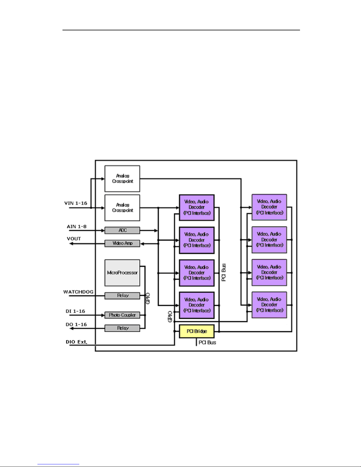
1.2 BLOCK DIAGRAM .............................................................................................................................1
2. FUNCTIONAL DESCRIPTION ..................................................................................................2
2.1 VIDEO ...............................................................................................................................................2
2.2 AUDIO............................................................................................................................................... 2
2.3 WATCHDOG ......................................................................................................................................3
2.3.1 WATCHDOG CONNECTOR CONNECTION DIAGRAM.................................................................... 3
2.4 ETC................................................................................................................................................... 3
3. HARDWARE INSTALLATION...................................................................................................4
3.1 AS3200V2 COMPONENTS............................................................................................................. 4
3.2 CAPTURE CARD COMPONENT DESCRIPTION ................................................................................. 5
3.3 CONNECTION WITH PERIPHERAL ....................................................................................................7
4. ELECTRICAL SPECIFICATIONS.............................................................................................8
4.1 RECOMMENDED OPERATING CONDITIONS ....................................................................................8
4.2 POWER SUPPLY CURRENT REQUIREMENTS.................................................................................... 8
5. OPTION CARD.................................................................................................................................9
5.1 AUDEXT3 CARD ..............................................................................................................................9
5.1.1 AudExt3 CARD PICUTRE.................................................................................................. 9
5.1.2 AudExt3 CARD COMPONENTS ....................................................................................... 9
6. AS3200V2 INSTALLATION GUIDE ....................................................................................10
iv www.alnetsystems.com 2004-04-02

AS 3000
1. Product Overview
1.1 Overview
AS3200V2 is a video capture card for PC based DVR and supports audio capture,
digital input, digital output, and watchdog function as well as video capture.
Video/audio data which is input through AS3200V2 is uncompressed raw data of
which compression and recording should be done by software on PC.
1.2 Block Diagram
7/14/2003 www.alnetsystems.com 1

AS 3200V2 Hardware Manual
2. Functional Description
2.1 Video
- Video Input
Number of Channel: 16
Input : Color Camera (NTSC, PAL), Black and White Camera
Connections : 15pin DSUB Cable 2EA, 40pin connector(used to connect to
real-time display card)
Recommended Signal Range: 0.5V ~ 2V (p-p)
- Video Capture
Classification NTSC PAL
Capture Resolution
640*480, 640*240,
320*240, 240*160,
160*120
768*576, 768*288,
720*576, 720*288,
640*480, 640*240,
384*288, 360*288, 320*240
Capture Rate Max 240 FPS Max 200 FPS
Capture Rate per
Channel 15 FPS ~ 30 FPS 12.5 FPS ~ 25 FPS
- Video Output
Number of channel : 1(channel selection possible, controlled by software)
Connection : RCA Jack or Molex 2Pin Connector
2.2 Audio
- Audio Input, Capture
Number of Channel : 8
Input Type : Microphone, Line(mono)
Recommended Signal Range : 1V(p-p)
Sampling Quality
►8, 16bit/sample (A/D Convert Sampling)
►4, 8, 16, 32 kHz Sampling
2www.alnetsystems.com 2004-04-02

AS3200V2 Hardware Manual
2.3 Watchdog
Watchdog works by relay switch and two connectors (J1, J2) are respectively a
2pin pinheader. J1 and J2 physically do the same operation; one is connected to
reset connector of mother board and the other to reset connector of the case. Or
the vice versa.
The interval of watchdog operation is set by software.
2.3.1 Watchdog Connector Connection Diagram
2.4 Etc.
- PCB : 4-Layer, PCI
2004-04-02 www.alnetsystems.com 3

AS 3200V2 Hardware Manual
3. Hardware Installation
3.1 AS3200V2 Components
6
7
8
9
5
10
4
3
2
2. AIN 1-8(J3, J4) : 5Pin Molex Box Connector x 2 for Audio Signal
3. VIN 1-8(J6) : DSUB-15 Female Connector
4. VIN 9-16(J8) : DSUB-15 Female Connector
5. VOUT(J14) : External Video Out RCA Jack
6. VOUT(J12) : External Video Out Molex 2Pin Connector
7. SW1, SW2 : 16Pin DIP Switch x 2
8. VIN 1-16(J5) : 40Pin Box Connector for Video Signal
9. WATCHDOG(J1, J2) : 2Pin Pinheader x 2
10. DIO (J15) : 20Pin Box Connector
4www.alnetsystems.com 2004-04-02

AS3200V2 Hardware Manual
3.2 Capture Card Component Description
2 AIN 1-8 5Pin Molex Box Connector(J3, J4)
This is a connector for Audio Input 1-8 and connected to J2 and J3 of AudExt3
Card. (AudExt3 Card is option.)
3 VIN 1-8 DSUB-15 Female Connector(J6)
This is a video input connector. Connect this to camera output port with the
provided DSUB cable.
4 VIN 9-16 DSUB-15 Female Connector(J8)
This is a video input connector. Connect this to camera output port with the
provided DSUB cable.
5 VOUT RCA Jack(J14)
This is a RCA jack for external video out. This is connected to Video In of TV
monitor.
2004-04-02 www.alnetsystems.com 5

AS 3200V2 Hardware Manual
6 VOUT Molex 2Pin Connector(J12)
This is a video out Molex 2Pin connector.
7Terminal Register 16Pin DIP Switch(SW1, SW2)
This switch is used to choose termination resistor (75Ω) in VIN1-8(SW1) and
VIN9-16(SW2). Please set the switch ‘ON’ to set to the termination resistor.
8 VIN 1-16 40Pin Box Connector(J5)
This is a video signal input connector. It is connected to the VIN1-16 connector
of real-time display card when user uses the real-time display card with
AS3200V2. To prevent misconnection, the connector was grooved.
9 WATCHDOG 2Pin Pinheader * 2(J1, J2)
Two watchdog 2pin pinheaders are respectively connected to reset connector of
mother board and reset connector of system case. The pin has no polarity.
10 DIO 20Pin Box Connector(J15)
This connector is used to test DI/DO and connected to extension card. (Please
refer to Extension Card Manual for more details.)
6www.alnetsystems.com 2004-04-02

AS3200V2 Hardware Manual
3.3 Connection with Peripheral
2004-04-02 www.alnetsystems.com 7

AS 3200V2 Hardware Manual
4. Electrical Specifications
4.1 Recommended Operating Conditions
Parameter Min Typ Max Units
Power supply +5V 4.75 5 5.25 V
Power supply +12V 11 12 13 V
Power supply -12V -11 -12 -13 V
Peak to Peak
Amplitude 0.5 1 2 V
Sync Amplitude 143 286 572 mV
Horizontal Lock
Range - - ±7
% of
Line
Length
Video
Input
Range
Color Sub-
carrier Lock-in
Range
- - ±800 Hz
Audio Input Range 0.01 2.593 3.3 VP-P
Ambient Operating
Temperature 0 65 °C
Ambient Operating
Humidity 0 90 %
4.2 Power Supply Current Requirements
Parameter Max Units
Power supply
+5V 2047 mA
Power supply
-12V 52 mA
8www.alnetsystems.com 2004-04-02

AS3200V2 Hardware Manual
5. Option Card
5.1 AudExt3 Card
5.1.1 AudExt3 Card Picture
1
2
3
5.1.2 AudExt3 Card Components
1 AIN 1-4 5Pin Molex Box Connector(J2)
This is used to transfer the input CH. 1 to 4 audio signals to AS3200V2.
2 AIN 5-8 5Pin Molex Box Connector(J3)
This is used to transfer the input CH. 5 to 8 audio signals to AS3200V2.
3AIN 1-8
This is used to input audio signals from external. Connect it with 9pin DSUB to
8RCA cable.
2004-04-02 www.alnetsystems.com 9

AS 3200V2 Hardware Manual
6. AS3200V2 Installation Guide
. Components
- AS3200V2 Capture Card
- 2PIN Cable (For Watchdog)
. Option Components
- AudExt3 Card
- ConExt1616 Card
- ConExt1200 Card
- ConExt0012 Card
- ConExt1604 Card
- ConExt0404 Card
- PTZExt2 Card
Option Components are optional. User can select DI/DO extension cards among
the above. Cables are provided with the selected DI/DO ext cards.
. Hardware Installation
(1) As the below, connect AS3200V2 Capture Card to AudExt3 and ConExt1616.
<AudExt3 and ConExt1616 Connected to AS3200V2>
10 www.alnetsystems.com 2004-04-02

AS3200V2 Hardware Manual
(2) Insert AS3200V2 vertically into PCI slot from one side to the other and then
insert AudExt3 and ConExt1616 in the same way. Check if the cards were well
inserted into PCI slot.
<AS3200V2, AudExt3 and ConExt1616 Inserted into PCI Slot>
(3) Connect a pin of watchdog 2pin connector of AS3200V2 to the reset switch of
mother board by 2pin cable. And then connect the other pin of watchdog 2pin
connector to the reset cable of PC case. Hardware installation of capture card
finished.
<Watchdog Pin Connected to Reset Pin of Mother Board>
2004-04-02 www.alnetsystems.com 11

AS 3200V2 Hardware Manual
12 www.alnetsystems.com 2004-04-02
III. Cable Connection
(1) DSUB 15PIN Cable
DSUB 15PIN cable is used for video input (J6, J8) of AS3200V2 capture card.
Connect it as the below picture.
VIN1~VIN8 Terminal(J6)
-Video In 1~8 Channel
VIN9~VIN16 Terminal(J8)
-Video In 9~16 Channel
(2) External Monitor Output Terminal (J14)
External monitor output port (RCA jack) is connected to external monitor.
Note
The video input port of DSUB 15pin is BNC type. To use RCA type, use a BNC to
RCA Converter.
Table of contents