NEC N8116-48 User manual

CBZ-001279-048-01
1
大切に保管してください
Keep this manual carefully along with the product
この度は、本製品をお買い上げいただきまして誠にありがとうございます。
Congratulations for your purchase of this Graphics Card Installation kit.
本製品を取り扱う前に本書の内容をよく読み、指示に従ってください。また、本製品を取り付ける前に、
取り付ける本体に添付の「ユーザーズガイド」に記載されている注意事項も参照してください。また、増
設にあたっては、最寄りの保守サービスセンターに依頼することをお勧めします。
The User's Guide is intended to allow you to install and use the Graphics Card Installation Kit.
N8116-48 correctly and safely. Read this manual thoroughly before handling the Kit.
In addition, refer to this guide whenever you want to know how to use the Kit or some malfunction occurs.
Always keep this guide at hand so that you can see it when necessary.
For the server in which the Kit is installed, refer to the User’s Guide of the server.
Read “Notes on Use”carefully before handling the Kit.
警告
WARNING
安全上のご注意を無視する取り扱いを行うと、装置の故障、人体事故、火災・周囲の機器の損傷を
引き起こす原因となることがあります。
Indicates the presence of a hazard that may result in death or serious personal injury.
オプションの取り付け、取り外し時は電源プラグをコンセントから抜 電源プラグを抜く
き、外部装置と接続しているケーブルを外してください。 Unplug the power
故障や感電する恐れがあります。
cord!
When you install the option or delete it, unplug the power cord and 感電注意
extract
the
cable
that
has
connected
to
another one.
Otherwise, an electric shock or fire may be caused. Precaution against
electric shock
分解禁止
Prohibition of
本書に記載されている場合を除き、絶対に分解したり、修理・改造を
disassembly
行ったりしないでください。装置が正常に動作しなくなるばかりで 発火注意
なく、感電や火災の危険があります。
Indicates
that
Do not
disassemble,
repair,
or
modify
the
server.
Otherwise,
an
improper
use
may
electric shock or fire may be caused.
cause
fire.
感電注意
Precaution against
electric shock
N8116-48 グラフィックスボード搭載キット
取り扱いの手引き
N8116-48 Graphics Card Installation Kit
User’s
Guide
CBZ-001279-048-01

CBZ-001279-048-01
2
目次
Contents
本体装置の構成制限 …………………………………3
Compositionrestrictionofsystem
構成品…………………………………4
Compositionarticle
取り付け …………………………………6
InstallingN8116-48inServer
1.準備確認事項
…………………………………6
Preparationpointtobechecked
2.増設手順(K80/M60)
…………………………………6
ExtensionprocedureofK80/M60
3.増設手順(K40)
…………………………………13
ExtensionprocedureofK40
4.SDR アップデート手順
…………………………………19
OperatingProcedureofSDRUpdate
5.BIOS 設定手順(K80/M60)
…………………………………21
OperatingProcedureofBIOSSetup(K80/M60)

CBZ-001279-048-01
3
本体装置の構成制限
Compositionrestrictionofsystem
本製品を使用するときは、本体装置に対し下記の構成制限が適用されます。
The following composition restriction is applied to a system, when this product is installed.
■ 構成制限
Compositionrestriction
<K80/M60 搭載時の制限>
●温度条件は動作時5〜35℃。
●N8181-139電源ユニット(2x1000W)の電源ユニット搭載モデル。
●N8181-131非冗長ファン搭載モデル。
●N8154-772.5 型 HDD ケージは最大 2 台(2.5 型 HDD16 台)まで搭載可能。
●N8154-783.5 型 HDD ケージは最大 1 台(3.5 型 HDD4 台)まで搭載可能。
●PXEBoot/FCBoot はサポートしておりません
<K40 搭載時の制限>
●温度条件は動作時5〜35℃。
●N8181-139電源ユニット(2x1000W)の電源ユニット搭載モデル。
●N8181-131非冗長ファン搭載モデル。
<Composition restriction of K80/M60>
●Temperature conditions are 5 to 35℃.
●N8100-2479F Express 5800/T120g Model.
●N8181-131F Fixed FAN Kit Model.
●N8154-77F 2.5-inch Hot Plug Drive Cage Kit is up to 2set.
●N8154-78F 3.5-inch Hot Plug Drive Cage Kit is up to 1set.
●PXE Boot / FC Boot are not supported.
<Composition restriction of K40>
●Temperature conditions are 5 to 35℃.
●N8100-2479F Express 5800/T120g Model.
●N8181-131F Fixed FAN Kit Model.

CBZ-001279-048-01
4
構成品
Compositionarticle
項番
No.
品名
Name 数量
Number
備考
Comment 部品イメージ
Parts Image
1 リテーナー
RETAINER 1
グラフィックスボード(NVIDIA K40)用
For Graphics Card NVIDIA K40
2 ダクトモジュール
DUCT MODULE 1
グラフィックスボード(NVIDIA K80/M60)用
For Graphics Card NVIDIA K80/M60
3 ブラケット
BRACKET 1
リテーナー/ダクトモジュール取り付け用
For NVIDIA K40/K80/M60
4 DCケーブル A
DC CABLE A 1
電源ボード−グラフィックスボード接続(K40)
/電源ボード−DC ケーブル B接続(K80/M60)用
DC ケーブル(長さ 700mm)
(14-4+6+8+2+6PIN connecter)
L=700mm
For NVIDIA K40/K80/M60
5 DCケーブル B
DC CABLE B 1
DC ケーブル A−グラフィックスボード接続
(K80/M60)用DC ケーブル(長さ 160mm)
(8-8+8PIN connecter)
L=160mm
For NVIDIA K80/M60
6
リテーナー/ダクト
取
付用ネジ
For Retainer/Duct
Module
(SCREW SET A)
1
リテーナー/ダクトモジュール取り付け用
ネジ(3 個)
For Retainer/Duct Module
Three screws(M3)
For NVIDIA K40/K80/M60
7
グラフィックス
ボード固定用ネジ
For Graphics Card
(SCREW SET B) 1
ブラケット/PCI ブラケット取り付け用
ネジ(5 個)
For Bracket/PCI Bracket
Five screws(#6-32UNC)
For NVIDIA K40/K80/M60
8 SDR UPDATE TOOL
(Graphics Card
Installation Kit)
1
SDR アップデート用 CD-ROM
SDR Update CD-ROM.
For NVIDIA K40/K80/M60
9 取り扱いの手引き
User’s Guide 1
本書
This Book
10
保証書 1 This warranty is valid only in Japan.
取り扱い上の注意事項
Notes On Use
本製品を箱から取り出した後は、次の注意事項を必ずお守りください。
Please be sure to protect the following notes after picking out this product from a box.
●ほこりの多い場所や水などの液体のかかるおそれのある場所に置かないでください。
Do not use the server in the place where dust, water or liquid may pour.
●強い磁気を発生させるものの近くに置かないでください。
Do not use the server in the place where the strong electromagnetic waves generate

CBZ-001279-048-01
5
第三者への譲渡
Transfer to Third Party
本製品を第三者へ譲渡(または売却)する場合には、本書を一緒にお渡しください。
Make sure to provide this manual and all the accessories along with the product to a third party.
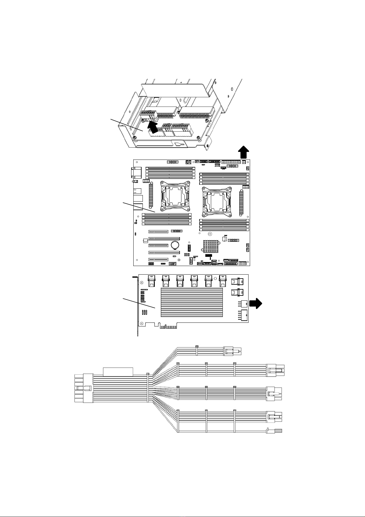
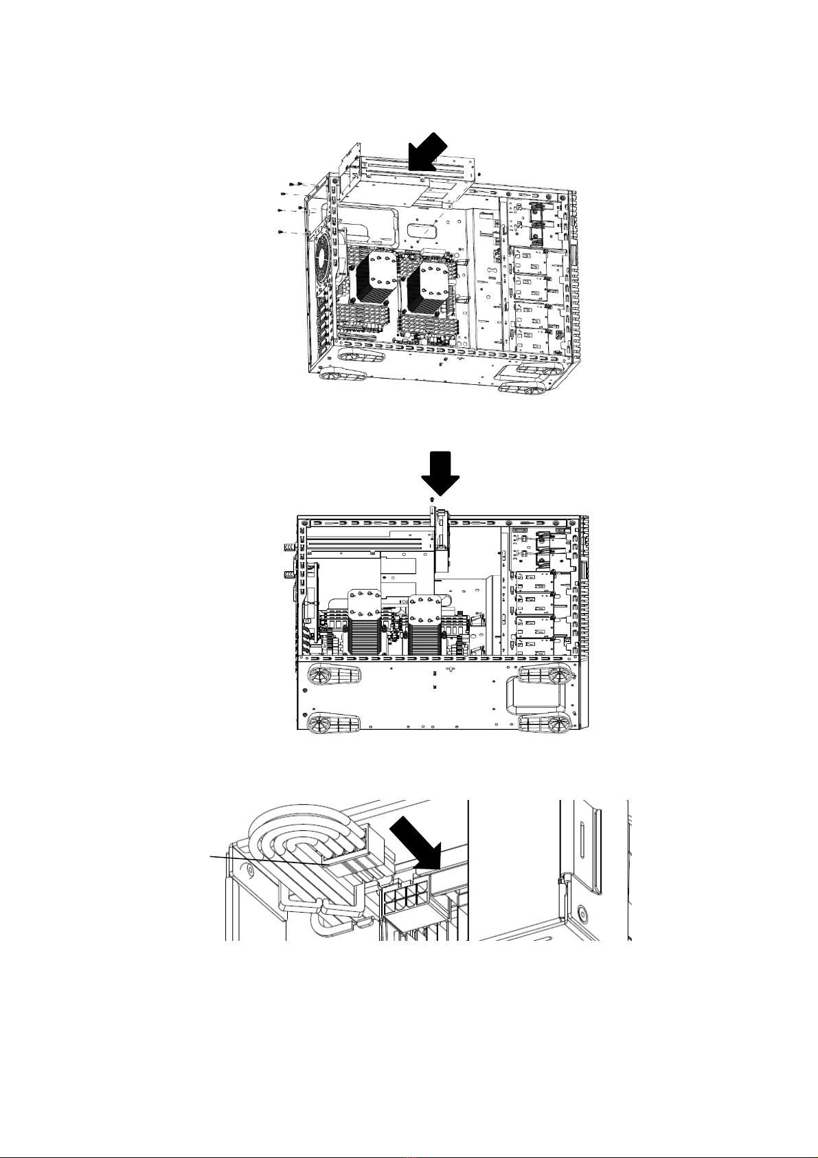
製品の取り付け/取り外しについて
Installing or Uninstalling an Internal Optional Device
準備確認事項
Notes before carrying out the work
(1)危険防止及び故障防止のため作業を行なう際には、本体装置の電源スイッチを OFF にし、電源
プラグをコンセントから抜いてください。但し、ホットスワップ(活線挿抜)対象製品の取り付
け/取り外し時の電源スイッチの OFF および電源プラグのコンセントからの取り外しは除きます。
To avoid electric hazard and malfunction, be sure to turn off the Power switch of this product and
unplug the power cord from an outlet before carrying out the work. However, there is no need to do
this if the internal optional device is hot-swappable.
(2)本製品は静電気に弱い電子部品で構成されています。製品の取り付け/取り外しの際は、静電気に
よる製品の故障を防止するため静電気対策用リストストラップなどの装着により静電気を除去
してください。また、リストストラップを使用する場合は、接地された箇所に接続して使用して
ください。
This internal optional device consists of static-sensitive electronic components. To avoid failures
caused by static electricity when installing or uninstalling the internal optional device, wear an
anti-static wrist strap on your wrist and provide earthing before carrying out the work. And also
connect a wrist strap to earth ground when you wear a wrist strap.
(3)ケーブルの取り扱い
Handling of cables
LANケーブル等のケーブルを接続する場合も床面との摩擦によって静電気が帯電することが
あります。帯電した状態で入出機器に接続すると機器を破壊することがありますので接続す
る前には除電キット等を使用して除電することを推奨します。
When connecting a cable (e.g., LAN cable), static electricity may also be charged due to friction
against the floor. Connecting a charged cable with an I/O device may cause damage to the
devices. It is recommended to discharge static electricity before connecting a cable by using
neutralization apparatus and so on.
注)静電気除電キットについて、下記の静電気除電キットについては、お買い求めの販売店
または保守サービス会社にご相談ください。
品名:LANケーブル除電治具
型名:SG001 (東京下田工業(株)製)

CBZ-001279-048-01
6
取り付け
InstallingN8116-48inServer
1.
準備確認事項
Preparationpointtobechecked
(1)危険防止及び故障防止のため、作業を行なう際には本体装置の電源スイッチを OFF にし、電源
プラグをコンセントから抜いてください。
To avoid danger and prevent malfunction, turn off the power of the server and unplug the power
plug from the outlet before performing the installation.
(2)本キット搭載には、PCI スロット#2/#3 を使用します。PCI スロット#2/#3 に他の PCI
カードが搭載されていないことを確認してください。
(PCI スロット#2/#3 を使用時には移動等により PCI スロット#2/#3 を空けてください。)
This Graphics Card Installation kit is installed on PCI slot#2/#3.Please confirm that PCI slot
#2/#3 are empty.(If other PCI card is installed on PCI slot #2/#3, please move from PCI
slot #2/#3.)
2.
増設手順(K80/M60)
ExtensionprocedureofK80/M60
2.1 ダクトモジュールに DC ケーブル Bを取り付けます。
Attach DC CABLE B to DUCT MODULE and routing into Cable Clamp.
2.2 ダクトモジュールのネジ止め用の蓋を開け、ネジ止め部分を確認し、
リテーナー取付用ネジ 3個にてダクトモジュールをグラフィックスボード(K80/M60)に取り付けます。
(リテーナー取付用ネジ 3か所)
Attach DUCT MODULE to Graphics Card with SCREW SET A 3 Screws.
Open rotate door to mount Screws and then close the door.
ダクトモジュール
DUCT MODULE
DC ケーブル B
DC CABLE B
ダクトモジュール
DUCT MODULE
グラフィックスボード(K80/M60)
Graphics Card(K80/M60)
リテーナー/ダクト取付用ネジ
For Retainer/Duct Module
(SCREW SET A)

CBZ-001279-048-01
7
2.3 サイドカバーを取り外します。
Remove Side Cover of Chassis.
2.4 CPU ダクトを取り外します。
Remove CPU Duct.
2.5装置本体の 3個のフロント FAN を取り外します。(ネジ 6か所)
Remove Front FAN x 3 pcs with 2 screws at 3 portions.
フロント FAN
Front
FAN
CPUダクト
CPU Duct

CBZ-001279-048-01
8
2.6 電源 FAN ケージを取り外します。 (ネジ 1か所)
Remove PSU FAN Cage with 1 screw.
2.7 電源ケージを取り外します。(ネジ 7か所)
Remove PSU Cage with 7 screws.
電源ケージ
P
SU
Cage
電源FAN ケージ
P
SU FAN Cage

CBZ-001279-048-01
9
2.8 電源ボード/マザーボード/エキスパンダカード上からエキスパンダケーブル(14pin)を外し、
DC ケーブル Aに交換します。
Remove Expander 14 Pin Cable from PSU BP, Expander Card, and Mother Board side.
Change this cable to DC Cable A.
DC ケーブル A 接続情報
DC cable A connection
電源ボード
P
SU BP
マザーボード
Mother Board
エキスパンダカード
Expander Card
グラフィックスボード Power
Graphics Card
(for K40/K80/M60)
グラフィックスボード Power
Graphics Card
(for K80/M60)
電源ボード
P
SU BP
マザーボード
Mother Board
エキスパンダカード
Expander Card
グラフィックスボード Power
Graphics Card
(for K40/K80/M60)

CBZ-001279-048-01
10
2.9 電源ケージを取り付けます。(ネジ 7か所)
Install PSU Cage with 7 screws.
2.10 電源 FAN ケージを取り付けます。 (ネジ 1か所)
Install PSU FAN Cage with 1 screw.
2.11 DC ケーブル Bとグラフィックスボード(K80/M60)を接続します。
Connect DC CABLE B to Graphics Card(K80/M60).
DCケーブル B
DC CABLE B

CBZ-001279-048-01
11
2.12 DC ケーブル AとDCケーブル Bを接続します。
Connect DC CABLE A to DC CABLE B.
2.13 フロント FANを取り付けます。(ネジ 6か所)
Put Front FAN x 3 pcs by 2 screws at 3 portions.
2.14 本体底面内側のマイラーをはがし、グラフィックスボード(K80/M60)をPCI#2 に搭載します。
Put Graphics Card(K80/M60) to PCIe slot-#2. And remove Mylar on chassis bottom inside first.
マイラー
Mylar
DC ケーブル B
D
C CABLE
B
DC ケーブル A
D
C CABLE A

CBZ-001279-048-01
12
2.15 ブラケットを本体底面のガイドに従い、本体底面よりグラフィックスボード固定用ネジ 2個を使用し
固定します。PCI ブラケット部分もグラフィックスボード固定用ネジ 2個を使用し固定します。
最後にグラフィックスボード固定用ネジ 1個を使用しダクトモジュールとブラケットを固定します。
(グラフィックスボード固定用ネジ 5か所)
Put BRACKET align with Chassis bottom guiding hole and screw in 1 screw B with Bracket but not
fasten. Then fix Graphics Card with 2 screw B on PCI Bracket, and then fasten 2 screw B on
Chassis bottom. Finally fasten screw B on BRACKET.
2.16 CPU ダクトを取り付けます。
Put CPU Duct.
2.17 サイドカバーを取り付けます。
Attach side cover.
ブラケット
BRACKET

CBZ-001279-048-01
13
3.
増設手順(K40)
ExtensionprocedureofK40
3.1 リテーナー取付用ネジ 3個にてリテーナーをグラフィックスボード(K40)カードに取り付けます。
(リテーナー取付用ネジ 3か所)
Attach RETAINER to Graphics Card(K40) with SCREW SET A 3 screws.
3.2 サイドカバーを取り外します。
Remove Side Cover of Chassis.
3.3 CPU ダクトを取り外します。
Remove CPU Duct.
CPUダクト
CPU Duct
グラフィックスボード(K40)
Graphics Card(K40)
リテーナー
RETAINER
リテーナー/ダクト取付用ネジ
For Retainer/Duct Module
(SCREW SET A)

CBZ-001279-048-01
14
3.4 装置本体の 3個のフロント FAN を取り外します。(ネジ 6か所)
Remove Front FAN x 3 pcs with 2 screws at 3 portions.
3.5 電源 FAN ケージを取り外します。 (ネジ 1か所)
Remove PSU FAN Cage with 1 screw.
3.6 電源ケージを取り外します。(ネジ 7か所)
Remove PSU Cage with 7 screws.
電源ケージ
P
SU Cage
電源FAN ケージ
P
SU FAN Cage
フロント FAN
Front
FAN

CBZ-001279-048-01
15
3.7 電源ボード/マザーボード/エキスパンダカード上からエキスパンダケーブル(14pin)を外し、
DC ケーブル Aに交換します。
Remove Expander 14 Pin Cable from PSU BP, Expander Card, and Mother Board side.
Change this cable to DC Cable A.
DC ケーブル A 接続情報
DC cable A connection
電源ボード
P
SU BP
マザーボード
Mother Board
エキスパンダカード
Expander Card
電源ボード
P
SU BP
マザーボード
Mother Board
エキスパンダカード
Expander Card
グラフィックスボード Power
Graphics Card
(for K40/K80/M60)
グラフィックスボード Power
Graphics Card
(for K80/M60)
グラフィックスボード Power
Graphics Card
(for K40/K80/M60)

CBZ-001279-048-01
16
3.8 電源ケージを取り付けます。(ネジ 7か所)
Install PSU Cage with 7 screws.
3.9 電源 FANケージを取り付けます。 (ネジ 1か所)
Install PSU FAN Cage with 1 screw.
3.10 DC ケーブル Aとグラフィックスボード(K40)を接続します。
Connect DC CABLE A to Graphics Card(K40).
DC ケーブル A
D
C CABLE A
グラフィックスボード(K40)
Graphics Card(K40)

CBZ-001279-048-01
17
3.11 フロント FAN を取り付けます。(ネジ 6か所)
Put Front FAN x 3 pcs by 2 screws at 3 portion.
3.12 本体底面内側のマイラーをはがし、グラフィックスボード(K40)をPCI#2 に搭載します。
Put Graphics Card(K40) to PCIe slot#2. And remove Mylar on chassis bottom inside first.
3.13 ブラケットを本体底面のガイドに従い、本体底面よりグラフィックスボード固定用ネジ 2個を使用し
固定します。PCI ブラケット部分もグラフィックスボード固定用ネジ 2個を使用し固定します。
最後にグラフィックスボード固定用ネジ 1個を使用しリテーナーとブラケットを固定します。
(グラフィックスボード固定用ネジ 5か所)
Put BRACKET align with Chassis bottom guiding hole and screw in 1 screw B with Bracket but not
fasten. Then fix Graphics Card with 2 screw B on PCI Bracket, and then fasten 2 screw B on
Chassis bottom. Finally fasten screw B on BRACKET.
マイラー
Mylar
ブラケット
BRACKET

CBZ-001279-048-01
18
3.14 CPU ダクトを取り付けます。
Put CPU Duct.
3.15 サイドカバーを取り付けます。
Attach side cover.

CBZ-001279-048-01
19
4.
SDR アップデート手順
OperatingProcedureofSDRUpdate
添付の「SDR Update Tool(Graphics Card Installation Kit)」で SDR の更新を行ってください。
Please be sure to update SDR with “SDR Update Tool(Graphics Card Installation Kit)”.
4.1 アップデートは、必ず本オプションを増設終了後に行ってください。
Please be sure to install option devices before updating SDR.
4.2 本体装置の電源を ONにします。
Turn on the power of server, and start the system.
4.3光ディスクドライブへ、添付の「SDR Update Tool(Graphics Card Installation Kit)」をセット
します。
Set the CD-ROM "SDR Update Tool(Graphics Card Installation Kit)"to optical disk drive of
the server.
4.4 <Ctrl>+<Alt>+<Delete>キーを押して本機を再起動させます。POST でエラーが出て、
キー入力を求められたときは、<F1>キーを押してください。
Press <Ctrl> + <Alt> + <Delete> keys to reset the server.
If "Press <F1> to resume" will be displayed, please press <F1> key.
4.5 「SDR Update Tool(Graphics Card Installation Kit)」から起動し、自動的に SDR データの
適用が始まります。
起動しないときは、BIOS のブート順位で CD/DVD-ROM ドライブが上位になっているか
確認してください。
以下のエラーが出たときは、誤ったメディアがセットされています。本オプションに添付
されたメディアを使ってください。
Error, incorrect server platform found.
SDR データの適用は、起動後 5〜6分かかります。
System starts from "SDR Update Tool(Graphics Card Installation Kit)" CD-ROM, and applying
SDR data starts automatically.
If the system fails to start, check if the highest priority is given to CD/DVD-ROM drive on BIOS SETUP.
If the following error displays, the incorrect media is set. Use the media provided with this product.
Error, incorrect server platform found
It takes about 5 or 6 minutes after system startup.
SDRデータの適用中は、絶対に電源を切断しないでください。
本体装置が起動しなくなる可能性があります。
Never attempt to power off the server while applying SDR data.
The server may fail to start.

CBZ-001279-048-01
20
次のような表示になれば、SDR データの適用は終了です。
When the message that as shown below displays, application of SDR data completes.
****SDR Current Revision *****
CFG Identify : ccfg1213
SDR Revision : SDR Version xx.xx
+-----------------------------------------------+
| SDR Update was successfully completed. |
| Please remove CD media and reboot system. |
+-----------------------------------------------+
Press R key to reboot system.
------------------------
r) Reboot system.
->
4.6 SDR Revision/CFG Identify が、以下の通り正しく表示されていることを確認してください。
Be sure to confirm SDR Revision / CFG Identify as follows.
※SDR Revision は「SDR Update Tool(Graphics Card Installation Kit)」に記載されて
いる Revision であること。
SDR Revision that described in SDR Update Tool(Graphics Card Installation Kit).
※CFGIdentify は”ccfg1213”(グラフィックスボード搭載設定) であること。
CFGIdentify is “ccfg1213”(This value is Graphics Card support setting.)
4.7「SDR Update Tool(Graphics Card InstallationKit)」を光ディスクドライブから取り出し、
<R>のキーを押します。本機が自動的に再起動します。
Remove the CD-ROM "SDR Update Tool(Graphics Card Installation Kit)" from
optical disk drive of the server.
Press <R> key on keyboard to restart the server.
以上で SDR アップデートは終了です。
The SDR update is finished.
Table of contents
Other NEC Video Card manuals
Popular Video Card manuals by other brands

Diamond Multimedia
Diamond Multimedia 4870PE5512DTXOC Specification sheet

Diamond Multimedia
Diamond Multimedia Radeon X1050 Specification sheet

ATI Technologies
ATI Technologies AT-009 Series user manual

Gainward
Gainward GTX260 1792MB GS Product specifications

Gainward
Gainward GTS250 1024MB brochure

ATI Technologies
ATI Technologies V3700 - Firepro 100-505551 256 MB PCIE Graphics... Specifications