Alpha Arsenal polus gsm User manual

3

4
POLUS GSM
THERMO SENSOR DETECTOR ALARM
Operating manual
TABLE OF CONTENTS
1 Description and Operation 4
1.1 Function 4
1.2 GSM Thermo Sensor Detector Alarm Package Contents 4
1.3 Technical Specifications 5
1.4 GSM TSDA Structural Design 5
1.5 External Temperature Sensor Structural Design 6
1.6 Function and Operation of the GSM TSDA 7
2 Set-Up 9
2.1 Preparing and Operating the GSM TSDA 9
2.2 Configuring the GSM TSDA 9
2.3 Accessing the Programming mode 10
2.4 Setting-up for the First Time Use 11
2.5 Verifying set-up 12
2.6 Changing & Adjusting the Parameters 12
2.7 GSM TSDA Installation 13
3 Troubleshooting the GSM THERMO Sensor Alarm Detector 14
4 Contact Us 15
5 Warranty 15

5
1 Description and Operation
1.1 Function
The GSM THERMO Sensor Alarm Detector is designed to monitor temperature in a
controlled environment, and when pre-set temperature thresholds are triggered in the monitored
zone, it will transmit an SMS “ALARM” notification and/ or place a call to your mobile telephone (up
to six (6) numbers).
The GSM TSDA is designed to monitor temperature in apartments, homes, country retreats,
steam rooms, saunas, garages, basements, vegetable storage units, incubators, refrigerators,
greenhouses, automobiles, outdoor facilities,etc.; it can also be used to monitor devices placed and
located near the Thermo Sensor, such as radiators, hot water heating system pipes, heated floors,
etc..
The GSM TSDA supports the following operational modes:
-Programming;
-“Armed On Guard”;
-“Alarm”;
-“Standby”;
GSM THERMO Sensor Detector Alarm FEATURES:
-Installs at any location with mobile GSM reception;
-Automatically resets to “Armed On Guard” mode after a triggered Alarm;
-The GSM TSDA is capable of monitoring temperature using the built-in or the external Thermo
Sensor*, as well as by using two external Thermo Sensors simultaneously;
-Arms and Disarms by simply turning power on or off.
-Settings programmable via mobile telephone, online and thru utilizing “Configurator Express GSM”
Android, iOS apps and the “GSM Central Control Monitoring Panel;
-Uses two notification languages: English and Russian;
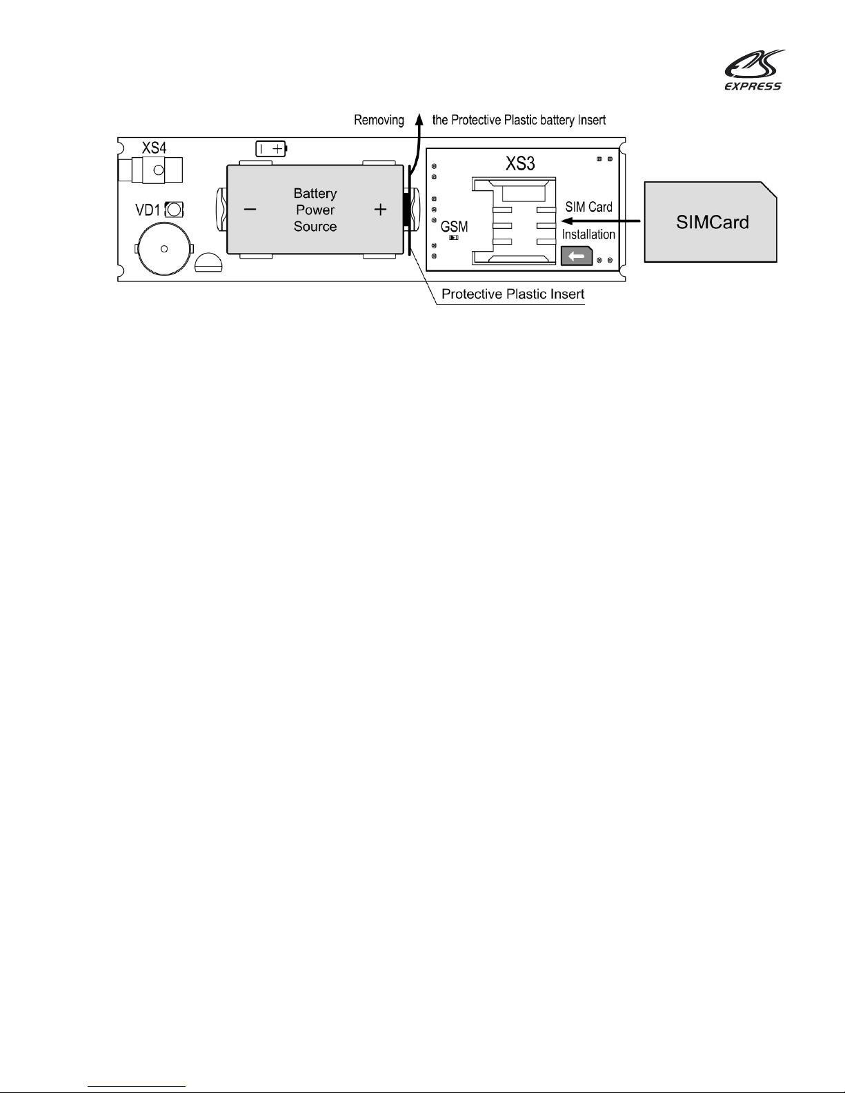
-Operates on a single 3 volt CR123 lithium battery for up to 12 months;
-Automatically identifies remaining SIM card balance inquiry telephone number;
*- The external Temperature Sensor is activated or de-activated by connecting or dis-connecting
the external Temperature Sensor cable jack into or out of the Detector Alarm socket. The built-in
Temperature Sensor can be dis-abled by setting unattainable temperature values (cells No.28&29,
Table4).
-The GSM TSDA is designed to operate indoors or near the item to be monitored and to monitor
around the clock 24/7 in stable non-extreme and non-explosive conditions.
1.2 Package Contents Include
in accordance with Table 1.
Table 1- Contents
Description
Quantity
GSM Thermo Sensor Detector Alarm -
(1) one
Lithium CR123A 3V battery-
(1) one
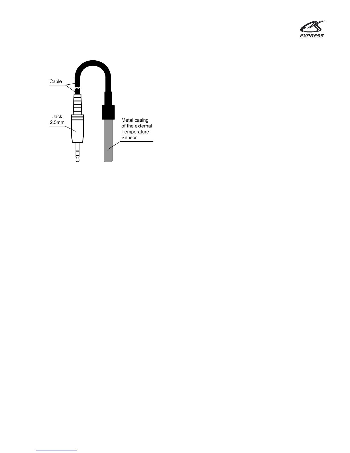
External temperature Sensor DS18B20
(cable L=1.5m, jack 2.5mm)-
(1) one
User's Manual-
(1) one

6
1.3 Technical Specifications
in accordance with Table 2.
Table 2- Primary Technical Specifications
DESCRIPTION
VALUE
Max. Number of telephones notified-
(6) six
Time lapse for notification-
20-40 seconds
GSM Module Operating Standards-
GSM-800/900/1800/1900
Detector temperature operating range-
from -10* to +50 C
Temperature measuring range of the
Built-in Sensor (limited to temp. operating
Range of the GSM TSDA)-
from -10 to +50 C
Temperature measuring range of the
External temperature Sensor-
from -40 to +99 C
Battery type-
1 x CR123A 3 V
Uninterrupted operating life span using one
battery at a temperature of +25C-
up to 12 months
Enclosure durability level-
IP40
Relative operating humidity @ +35С
сondensation, not to exceed-
93%
GSM TSDA size & dimensions
do not exceed-
109x32x27.5 mm
GSM TSDA (w/ battery) weight
does not exceed-
60 g
Temperature Sensor cable length-
1.5 m
* Please Note: The GSM TSDA can operate at a temperature of -25 C, but the operating battery life
span and quantity of SMS’s sent will be reduced.
1.4 GSM TSDA Structural Design
The GSM TSDA unit consists of a cover body with a LED indicator and a base (diag. 1 & 2).
The cover body has an opening (with pop-out plug) to connect the external Temperature Sensor
(diag. 2). Inside the cover body, mounted on the base, is the controller circuit board, to which the
GSM module is attached (diag. 3). The circuit board and cover body attach to the base unit using
clips. The cover body and base unit are made of ABS plastic.

7
Diagram 1: GSM TSDA design; General view
Diagram 2: GSM TSDA Design; Top & bottom view
The controller circuit board (refer to diagram 3) contains a: battery holder GB1, audio indicator
BQ1, two color LED indicators VD1 and a socket XS4 in order to connect a Temperature Sensor.
The two color LED indicates the state of the GSM TSDA in accordance with table 3.
The GSM module circuit board contains a SIM cardholder (XS3) and a “GSM” LED to indicate
network signal strength.
Diagram 3: Exposed view of the controller circuit board and GSM module
The GSM TSDA is shipped with an installed battery insulated from the contacts by a protective
plastic insert (refer to diagram 7).
1.5 External Temperature Sensor Design
The external Temperature Sensor is functionally identical to the built-in Temperature Sensor
(BK1). The external Temperature Sensor is enclosed in a metal casing to which a 1.5 meter cable
with a 2.5 mm jack is attached (see diag.4).

8
Diagram 4: External Temperature Sensor
1.6 Function and Operation of the GSM TSDA
1.6.1 Operational Principle of the GSM TSDA
While in “Armed On Guard” mode, when the set temperature thresholds are exceeded, the
GSM TSDA will receive an Alarm trigger signal from the Sensor, enter “ALARM” mode and will then
execute notifications.
1.6.2 Primary Functions of the GSM TSDA
The GSM TSDA executes the following functions:
- Manages temperature in a monitored zone (spot);
- Transmits SMS notifications and/or calls the list of notification telephone numbers (up to six
(6) numbers) programmed into the GSM TSDA SIM card memory when an “ALARM” is triggered;
- Automatically resets to “Armed On Guard” mode and transmits an SMS to the primary
notification telephone number;
- Automatically, requests remaining GSM TSDA SIM card balance and transmits an SMS to
the primary notification telephone number;
1.6.3 Operational modes of the GSM TSDA
Upon activating power (by either removing the protective plastic insert from in between the
battery and contacts or by inserting a battery), the GSM TSDAwill discover and connect to a GSM
network and then enter “Programming” mode;
One (1) minute after all the settings conclude, the GSM TSDA enters “Armed On Guard” mode.
While in “Armed On Guard” mode and when the pre-set temperature thresholds (low or high)
are violated, the GSM TSDA will enter “ALARM” mode and will then execute notifications via SMS
and/ or by placing outgoing calls.
After concluding “ALARM” notifications, the GSM TSDA enters “Stand By” mode.
While in “Stand By” mode, sensing no violations (when the temperature returns to within 2
degreesof the pre-set temperature low or high thresholds), the GSM TSDA automatically resets
to“Armed On Guard” modeand transmits an SMS (Diag.6) to the primaryNotification telephone
number.
The GSM TSDA is “Disarmed” by interrupting the power source by either replacing the
protective plastic battery insert or by removing the battery.

9
1.6.4 GSM TSDA Indicators
The GSM TSDA has built-in LED and sound indicators. In addition, the GSM LED indicates
GSM signal strength. Indicator descriptions can be found in Table 3.
Table 3- GSM TSDA Indicators
Event/ Mode
LED Indicator
Sound Indicator
GSM LED
Indicator
Power On
Glows Red
―
Glows Red 3 Sec.
GSM Network Search
Glows Red
―
Flashes for 20-40
Sec.
GSM Network Activation
(At Start-up)
Flashes Red/Green
3 Beeps
Once every 4sec.
Programming Mode
Glows Green
―
―
GSM TSDA
Incoming Call or SMS
―
Audio Beep
―
“Armed On Guard” Mode
―
―
―
“Alarm” Mode
High Temp. Threshold
Glows Red
―
―
“Alarm” Mode
Low Temp. Threshold
Glows Green
―
―
“Standby” Mode
―
―
―
1.6.5 Notifications
The GSM TSDA transmits “ALARM” SMS notifications to the numbers registered at
“1SMS”…”6SMS” (Diag.5). The primary number registered at “1SMS” will receive SMS notifications
containing the selected settings (Item 2.4, diag. 8), Test/status SMS notifications showing
remaining SIM card balance and Auto Reset to “Armed On Guard” mode (Diag. 6).
Test/status SMS notifications are sent depending on the interval selected (Table 4, Cell# 14).
The interval time reference point is established and starts upon the receipt of the settings
notification.
When an “Alarm” is triggered, the GSM TSDA will transmit an SMS notification, place a call to
the first registered (primary) number and will then place calls to the remaining numbers together
with transmitting SMS notifications (up to six (6) numbers).
The GSM TSDA will cease calling the first number and will proceed to call the next number
under the following circumstances:
- When the subscriber disconnects the incoming call;
- When the subscriber does not respond by picking-up within 30 seconds;
- When the subscriber’s line is busy;
- When the subscriber is out of network;
Calling out will cease after one of the subscriber numbers picks up and disconnects; then the
GSM TSDA will transmit “Alarm” (Diag. 5) notifications to the numbers located at cell positions
“2SMS”…”6SMS”.

10
Diag. 5 “ALARM” Notifications
Diag. 6 Auto Reset Notification
Tn- Temperature Sensor number: T1 or T2
T1- Built-in Temperature Sensor, T2- External Temperature Sensor
S- indicates GSM network signal strength;
NN- indicates GSM network signal strength as a percentage (e.g. S50%, S75%, etc.)
The value indicating GSM network signal strength (SNN%) is included in all SMS notifications,
except for notifications showing remaining SIM card balance.
2 Set-Up
2.1 Preparation of the GSM TSDA for Operation
After opening the package, visually inspect the GSM TSDA for any physical defects and to
confirm all item parts are included.
Prior to operating the GSM TSDA, disable the PIN number request feature on the SIM card
with the assistance of a mobile telephone (refer to mobile telephone user’s manual). Check and
verify there is a sufficient balance on the SIM card.
2.2 Configuring the GSM TSDA
At initial power-up, the GSM TSDA records on to the SIM card the following parameters and
values in accordance with Table 4.
Table 4- GSM TSDA Settings
Cell#
Cell
label
Default
Value
Description
Available Values
1
1sms
000
1st telephone
number (primary) for
notification
Enter number in the following format
+1********** e.g.:+17180000000
2
2sms
000
Telephone numbers
for notification
Enter number in the following format
+1********** e.g.:+17180000000
3
3sms
000
4
4sms
000
5
5sms
000
6
6sms
000
7
BALANS
0
Remaining balance
Inquiry USSD
Auto detection of remaining balance tel.
number;
Manual entry of tel.# e.g.: *100#
High temperature detected Тn SNN%
Low temperature detected Тn SNN%
Тn normal SNN%

11
Cell#
Cell
label
Default
Value
Description
Available Values
14
TEST
7
Frequency for test/
status SMS
notifications
Sets frequency for test/ status SMS
notifications. Interval sets up to 250 days.
e.g.:
1- Notification once a day
7- Notification once a week
0- Notification not sent.
18
AlarmNt
1
Alarm notification
Option/Type during
Alarm mode
0- Only SMS to
1sms...6sms
1- Call + SMS
(SMS sent to1sms, then calls placed to all
tel. numbers, followed by SMS transmittal
to all remaining tel. numbers @2sms...
6sms.
3- Only calls placed to 1sms...6sms
28
Tup1
40
Upper Temp.
Threshold for built-in
Sensor
Increments of 1 degree C,
from -10 C to +50 C
(asterisk) indicates (-)minus;
(+) plus not required
29
Tdown1
10
Lower Temp.
Threshold for built-in
Sensor
34*
POLUS
3
Template name
w/settings
3
35
Мnum
000
For operation
w/Polus
GSM Security Panel
application
Tel.№ Alarm Sensor
36
LANG
1
Notification
Language
0-Ru
1-En
38
Tup2
40
Upper Temp.
Threshold for
external Sensor
Increments of 1 degree C,
from -10 C to +50 C
(asterisk) indicates (-)minus;
(+) plus not required
39
Tdown2
10
Lower Temp.
Threshold for
external Sensor
*- Operating service data that creates template during GSM TSDA set-up.
2.3 Accessing the Programing Mode
In order to access “Programing” mode, consecutively execute the following actions.
1. Install the SIM card as shown in diag. 7.
Caution! Prior to installing or removing the SIM card, it is necessary to de-activate the GSM TSDA
electrical supply! (i.e. install the protective plastic battery insert or remove the battery).
2. Remove the Protective Plastic battery Insert from in between the contacts and the battery (see
diag. 7) or install a battery using correct polarity (if previously removed).

12
Diag. 7 SIM card installation; protective plastic battery insert removal
3. The GSM TSDA LED indicator will glow red. The “GSM” LED will glow for 3 seconds and will
begin to flash quickly.
4. Wait for the SIM card to register on to the GSM network. At the conclusion of registration, 3
beeps will be heard and the “GSM” LED will flash (1) once every (4) four seconds. The GSM TSDA
LED indicator will glow green. This indicates that the GSM TSDA has entered “Programing” mode.
During the entire duration of the “Programing” mode, the LED indicator will glow green.
In the event the “GSM” LED continues to flash quickly, (the SIM card is not registering on the
GSM network) and might be due to the SIM card being incorrectly or not installed, blocked by a PIN
code or the GSM network is inaccessible (take steps in accordance with table 5).
Upon entering “Programing” mode, the GSM TSDA sends an SMS notification with settings to
the primary notification telephone number (if the primary number was previously recorded in the
SIM card memory).
For the span of (1) one minute, the GSM TSDA remains in “Programing” mode and stands by
for an incoming call and/ or SMS containing any changes to the settings. In the absence of an
incoming call/ SMS, the GSM TSDA at the expiration of (1) one minute enters “Armed On Guard”
mode.
In the event of an incoming call/ SMS occurring and being accepted, the GSM TSDA at the
expiration of (1) one minute, will enter “Armed On Guard” mode and will transmit an SMS
notification reflecting the setting changes to the primary registered telephone number.
2.4 Setting-up for the First Time
After powering-up the GSM TSDA, a template with cells containing default values will be
created in the SIM card phone book (in accordance with table 4). Later on, you are able to edit and
alter these parameters and values.
It is necessary to record notification telephone numbers to the SIM card memory.
Perform the followings steps consecutively.
1. Access “Programing” mode in the device (see item 2.3).
2. Begin by calling the GSM TSDA SIM card telephone number from the telephone number that will
be used as the primary notification number. After receiving and recording the number, the GSM
TSDA will disconnect the call and emit (1) one audible confirmation beep. This number will be
recorded in cell# 1 “1SMS” (see table 4) as the designated primary number and will send an SMS
notification from the GSM TSDA indicating “Setting Reset, Number Added +1xxxxxxxxxx”.

13
3. Proceed to record any additional notification telephone numbers by calling from each of them
and after each additional number is recorded, an SMS notification is sent to the primary telephone
number containing “Number Added+1zzzzzzzzzz”, “Number Added+1zzzzzzzzzz” etc.
4. One (1) minute after the last call is received, the GSM TSDA will transmit an SMS containing the
settings (see diag. 8) to the primary telephone number and will then enter “Armed On Guard” mode.
If you were unable to record all the necessary additional notification telephone numbers, either
re-insert in the Protective Plastic Insert between the battery and contacts or remove the battery,
wait (2) two minutes and then repeat the procedure from the beginning- see item 2.6.
Diag.8- Sample SMS with Settings
2.5 Verifying Set-up
1. Attach the external Temperature Sensor by inserting the jack into the GSM TSDA XS4
socket.
2. Place the Temperature Sensor in a location where the temperature exceeds 40 degrees
Celsius (e.g. place under a hot lamp).
3. Within a few seconds, the GSM TSDA LED indicator will glow Red and will trigger into
“ALARM” mode. (afterwards, place the Temp. Sensor in normal conditions by removing it from
under the hot lamp).
4. Wait to receive an SMS notification containing the text “High Temperature Detected T2” and
an incoming telephone call from the Alarm Detector (acknowledge by disconnecting the incoming
call). After the concluding the notifications, the LED indicator will turn off and the GSM TSDA will
enter “Standby” mode.
5. After the Temperature Sensor cools off (temperature falls below 38 C), the GSM TSDA
automatically resets and enters “Armed On Guard” mode. Wait to receive an SMS showing “T2
Normal”.
2.6 Changing the Parameter Value Settings
Value parameter settings are installed during the (1st) first power-up and can later be changed.
The parameter values can be changed using the following methods.
Method-1
The GSM TSDA settings can be configured by using the “Online Service” located at service.alpha-
safe.com, by utilizing the “Express GSM Configurator” for Android or iOS or by using the application
for central monitoring “GSM Panel” available for download from play.google.com (search: “Express
GSM” or “GSM Panel”).
The created configuration will be sent to the GSM TSDA SIM card.
1) Primary notification number
14) Frequency of
test/status Notifications
GSM TSDA number
Received from +1YYYYYYYYYY
1)+7XXXXXXXXXX,7)*100#,
14)7,18)1,28)40,29)*10,
36)1,38)40,39)*10,SNN%
7)Balance Inquiry
18) Alarm notification option
36) Notification language
Signal Strength
28) Upper Temp. Threshold 1
29) Lower Temp. Threshold 1
28) Upper Temp. Threshold 2
29) Lower Temp. Threshold 2

14
Method-2
1. Using the primary notification telephone, create an SMS message using values in accordance
with table 4.
For example, in order to change the notification method, it is necessary to send an SMS
message containing the following text(Characters are entered without quote marks and spaces):
“18)0”; where 18) indicates the cell number and 0 indicates the selectedparameter value.
In order to change several parameters at once, it is necessary to list the parameters separating
them with a comma. For example: “2)+1xxxxxxxxxx,18)3,28)25,29)15,36)1,38)95,39)*30” etc.
Note: Characters are entered without quote marks and spaces.
2. Access “Programing” mode in the GSM TSDA (item 2.3).
3. Send a previously prepared SMS message to the GSM TSDA telephone (SIM card) number.
4. Wait to receive an SMS notification confirming the selected parameter values.
Method-3
It is possible to change and configure the parameter values directly with the aid of a GSM
mobile telephone. In order to accomplish this, install the GSM TSDA SIM card into any GSM mobile
telephone. To access the necessary parameter, open the telephone book, select the cell to be
altered and make the necessary changes in accordance with table 4.
For example, in order to change the primary notification telephone number, in the telephone
book select “1SMS”, then select “change”, erase the old number and record the new primary
notification telephone number, etc.
Note: Some mobile telephone models do not support this function.
In addition to the change parameter methods listed above, adding/ deleting notification
telephone numbers can also be accomplished via a telephone call from the primary notification
telephone number to the GSM TSDA while in “Programing” mode. After calling from the primary
notification telephone number, all telephone numbers contained in the SIM card memory are
erased and it will be necessary to re-add all required telephone numbers all over again. Attention!
This action resets all settings to the default settings (as shown in Table 4).
2.7 GSM TSDA Installation
The GSM TSDA should be installed at a location that will be shielded from atmospheric
elements, physical damage and access by unauthorized persons and will have access to a reliable
GSM signal.
The GSM TSDA should be located away from high power electrical cables.
In order to install the GSM TSDA, consecutively execute the following steps:
1. Select a location to install the GSM TSDA, bearing in mind that the Temperature Sensor
connection cable is 1.5 meters in length.
2. Mark-up the selected installation location bearing in mind measurements and the location of
mounting holes as located on the GSM TSDA base.
68 мм
Diag. 9- Installation Size Specifications

15
3. Install the GSM TSDA by removing the cover and the circuit board from the base. Attach the
base using two screws, then snap-in the circuit board and then replace the cover.
Double-sided tape can be used to mount the GSM TSDA on to a properly prepared surface.
4. Connect the Temperature Sensor to the GSM TSDA. Prior to making the connection, it is
necessary to break-out the plastic plugs from the connection opening.
5. Verify operation in accordance with item 2.5.
6. Install the external Temperature Sensor at a location where temperature needs to be monitored,
bearing in mind that the external Temperature Sensor is enclosed inside a metal casing (see diag.
10).
7. Run the Temperature sensor connection cable in a manner that does not interfere with moving
about the monitored location.
Diag. 10- Sensitive Operating Surface of the external Temperature Sensor
3 Troubleshooting the GSM TSDA
Table 5- Troubleshooting Guide
Description of Symptom
Possible Cause
Solution
No Audio beeps or “GSM”
LED flashes in the GSM
TSDA after the Battery is
installed.
1. Battery improperly
installed;
2. Battery is discharged
1.Remove the battery & re-install
properly using proper polarity;
2.Install a new fresh Battery:
CR123A 3V
After powering up the GSM
TSDA detector (inserting the
battery) the “GSM” LED
flashes rapidly & does not
flash once (1) Every (4) four
seconds as Required (SIM
card is not Logging on to the
network)
1.SIM card is not installed;
2.SIM card is incorrectly
installed;
3.SIM card is locked with
a PIN code;
4.”GSM” network is
inaccessible.
1.Verify the presence of a SIM card;
2.Remove SIM card & re-
install as shown in diag.7;
3. Disable the SIM card PIN code
feature by using a GSM Telephone
(see tel. operating manual).
4.(a) Re-locate the GSM TSDA to a
location with good access to a GSM
Network signal (in accordance with
item 2.7 in this user’s manual
(b)Change the mobile Network
provider.
When verifying operation with
the Ext. Temp. Sensor, the
GSM TSDA Does not enter
“ALARM” mode, LED does not
glow Red, no Notifications
triggered.
1. Faulty contact between the
Temp. Sensor jack and the
GSM TSDA socket.
2. Insufficient temp. to
Trigger threshold.
1.Verify connection.
2. Create sufficient temp. or reduce
temp. Threshold.

16
4 CONTACT US
ALPHA ARSENAL, LLC
104-20 Queens Blvd., Ste 1B
Forest Hills, NY 11375, US
T/F: +1.718.440.3281
+1.718.355.9281
Skype: alpha.arsenal
E-mail: info@alpha-safe.com
support@alpha-safe.com
Website: www.alpha-safe.com
5Warranty Coverage
The warranty period is one year from date of purchase. During the Warranty period, the
manufacturer will repair, exchange, adjust, or replace at its discretion, any defective product. This
warranty does not cover damage resulting from any unauthorized attempts to repair or from any
use not in accordance with the instruction manual. The warranty does not cover physical damage of
any kind whatsoever nor does it cover damage caused by any attempt to tamper with or
disassemble the product. The warranty coverage does not extend to the batteries. The warranty
period commences on the day first purchased from the manufacturer or an authorized reseller as
evidenced by a purchase receipt. Without a valid purchase receipt, the manufacturer is relieved of
its obligation to provide warranty service.

17
Other manuals for polus gsm
1
Table of contents
Other Alpha Arsenal Accessories manuals
Popular Accessories manuals by other brands

Orno
Orno OR-CR-262 manual

Desa
Desa JourneyMan HD-9140 user manual

HTC
HTC BB G1000 quick start guide

PCB Piezotronics
PCB Piezotronics 117B205 Installation and operating manual

Lanaform
Lanaform Aroma Spring Instructions for use

Stobag
Stobag SKIROSOL SRCK 630 Instructions and warnings for installation and use

elsner elektronik
elsner elektronik Sewi KNX L Installation and adjustment

BEA
BEA EAGLE ONE HM user guide

Urban Factory
Urban Factory The Brick Battery user guide

Pfeiffer Vacuum
Pfeiffer Vacuum CCR 361 operating instructions

SICK
SICK T-EASIC FTS operating instructions

Hella
Hella PM07 protect Installation instructions and instructions for use