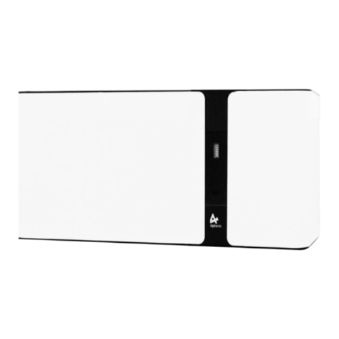
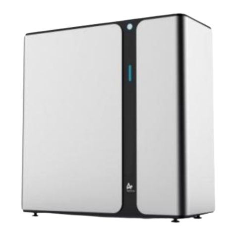
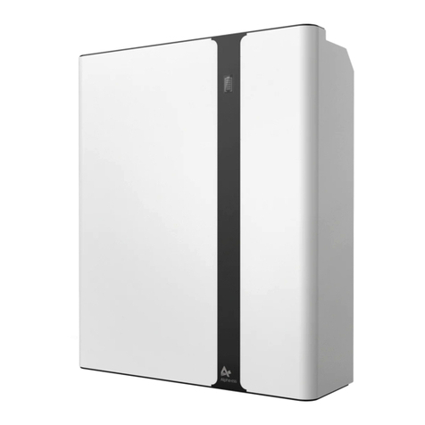
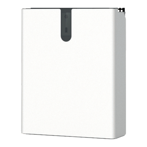
Alpha ESS SMILE-BAT-10.3P User manual

QUICK INSTALLATION GUIDE
SMILE-BAT-10.3P INTEGRATED EMS
V01

1 x Quick Installation Manual 6 x ST6*55
Wall Anchor 2 x Wall Panel
4x M5 Washer 1 x WiFi Module (optional)
2 x Power Cable
(1 black, 1 red) 8 x M5*10 Screw
1 x Battery Communication Cable
SMILE-BAT-10.3P Integrated EMS

Mount the Wall Panels
Place the battery against the wall, cover the top of the battery
with plastic bag and drill 4 holes on the wall with drill Φ10.
Remove the plastic bag and secure the battery to the wall with
screws (Tool: SW10screwdriver).
ST6X55 Wall Plug
2 x Wall Panels
Drill Holes(Φ10 *65mm )
Cover the top of the battery to avoid the dirt.
Mount the Battery
Assemble the mounting panels on the top of the battery
(tool:2# Phillip'sscrewdriver, torque:2.5Nm).
Take out the battery from the packing box, and remove
the cardboard support.
4 x M5*10 Screws

Open the front panel and the battery maintenance panel, turn off
the batterycircuit breaker.
Open the communication panel on the right side, you will see the
EMS communication board and battery communication board.
Connect the communication cables from the EMS/battery
communication board to the other devices.
Maintenance Window for
BatteryCircuit Breaker
Turn off the battery
circuit breaker
Communication Cable Wiring
Open Maintenance Window
OFF ON
EMS Communication Board
Battery Communication Board
1. Meter, please read electricity meter
wiring instructions
2. LAN, establish a wired connection to the
local network (e.g. via a router)
3. LAN, establish a wired connection to the
local network (e.g. via a router)
4. BMS, communication connection for
battery expansion
Standard Configuration: 1x
Communication Cable 1
Installation Method of
Communication Cable
via M25 Cable Gland

Connect the power cable from the battery 1 to the inverter.
Power Cable Conncection
2 x Power Cable
(1 black, 1 red)
Left
View Right
View
1x WiFi Module 2 x M4*12 Screws
WIFI Module Installation
Step7
Remove the WiFi panel on the right side and install the WiFi
module(tool: T20 screwdriver, torque: 1.6Nm). Please read
configuration network instructions.
WiFi
Panel
Optional WiFi module.
Connect the power cables from battery 2 to battery 1.
Batteries Expansion Connection
Step8
Red - Red
Black - Black
Connect the communication cables from battery 2 to battery 1.
Connect batteries first if more batteries are to be added.
Step9
To Inverter
Earthing Position

Close Maintenance Window
Close the two maintenance panels and the battery front panel.
( Tool: T20 screwdriver, torque: 2.5Nm)
Turn ON the batterycircuit breaker.
Step10
Communication Connection Window
Maintenance Panel for BatteryCircuit Breaker
Step11
......
Install another battery, please repeat Steps 1 ~ 10.
Please install extra batteries only by the side if more are to be added.
You can add up to 6 batteries in a system.
Add Extra Batteries
The complete system needs EMS, the first battery should be the one
with EMS
Configuration of DIP Switch
1. If there is only one battery, DIP switch of battery should be set as
below:
2. If there are two or more than two batteries, DIP switch of batteries
should be set as below:
Battery
Position
Other
BAT
Farthest
BAT
OFF
OFF
OFF
ON
OFF
OFF
OFF
OFF
DIP 1 DIP 2 DIP 3 DIP 4 DIP
Switch
Battery
Position
One BAT OFF OFF OFF OFF
DIP 1 DIP 2 DIP 3 DIP 4 DIP
Switch

System Connection Diagrams
1-AC Breaker ≥ 50A for Goodwe 5000S-BP
inverter
2-In Australia and New Zealand, the neutral
of backup and grid circuit should be
externally connected on the neutral bar.
CAN/RS485
Meter
SMILE-BAT-10.3P
Integrated EMS
Battery Inverter
Critical
Loads
Router
LAN
WiFi
AlphaCloud
Monitoring
Device
Normal
Loads
GridGrid Meter
PV
Meter
PV
Inverter
PV
Electricity Meter Wiring
The power meter should be installed and
connected in the distribution box. There are
3 types of power meters, available for
ADL-3000, SM60A or ACR10R.
SM60A: Single-phase electricity meter (with
or without meterplug)
ADL-3000: Three-phase electricity meter
(with or without meterplug)
ACR10R: Three-phase CT electricity meter
(with CT)
Meters should only be purchased from
AlphaESS.
1. Electricity Meter SM60A (if optional)
1.1 SM60A Connection (without meterplug):
Note: Terminal 5, 6 connecting RJ45
PIN 3, 6
RJ45
EMS
AlphaESS
3 56 6 5 6
RS485 PIN
Grid Meter
RS485 PORT
PV Meter
RS485 PORT
12345678
ADD: 003
ADD: 004
PV
METER
RJ45 RS485
6
3
CT
METER
CAN
RS485
LAN BMS
GRID
METER
L
5 6 7 8
L’ N N’
PV INV
GRID
L
BACK-UP ON-GRID
N PE L N PE
L L’ N N’
5 6 7 8
LOAD
SBP
PE
SMILE-BAT-10.3P+EMS+WIFI
RJ45

Note: Terminal 7, 8
connecting RJ-45 PIN 3, 6.
Electricity Meter Wiring
1.2 SM60A Connection (with meterplug):
2.1 ADL-3000 Connection (without CT, without meterplug):
2. Electricity Meter ADL-3000 (if optional)
AlphaESS
3 76 8 7 8
RS485 PIN
Grid Meter
RS485 PORT
PV Meter
RS485 PORT
ADD: 003
ADD: 004
PV
Meter
CT
Meter
CAN
RS485
LAN BMS
Grid
Meter
L
5 6 7 8
L’ N N’
PV INV
GRID
L
BACK-UP ON-GRID
N PE L N PE
L L’ N N’
5 6 7 8
LOAD
SBP
PE
SMILE-BAT-10.3P+EMS+WiFi
Ethernet Cable
CT
Meter
CAN
RS485
LAN BMS
L
BACK-UP ON-GRID
N PE L N PE
SBP
PE
SMILE-BAT-10.3P+EMS+WiFi ADL-3000
L1
L1’ L2’ L3’
L2
9 10 1112
L3 N
N’
ADL-3000
L1
L1’ L2’ L3’
L2
9 10 1112
L3 N
N’
GRID
LOAD
PV INV
ADD: 002
PV
Meter
ADD: 001
6
3
7 8
7 8
RJ45
Grid
Meter
RS485
RJ45
12345678

Note: Please pay attention
to the CTs direction.
Electricity Meter Wiring
2.2 ADL-3000 Connection (without CT, with meter plug):
3. Electricity Meter ACR10R (if optional)
ADD: 005
SMILE-BAT-10.3P+EMS+WiFi
AlphaESS
3 216 22 21 22
RS485 PIN
Grid Meter
RS485 PORT
PV Meter
RS485 PORT
12345678
CT
Meter
CAN
RS485
LAN BMS
L
BACK-UP ON-GRID
N PE L N PE
SBP
PE
SMILE-BAT-10.3P+EMS+WiFi ADL-3000
L1
L1’ L2’ L3’
L2
9 10 1112
L3 N
N’
ADL-3000
L1
L1’ L2’ L3’
L2
9 10 1112
L3 N
N’
GRID
LOAD
PV INV
ADD: 002
PV
Meter
ADD: 006
PV
Meter
ADD: 001
7 8
7 8
Grid
Meter
Grid
Meter
Plug
Plug
Ethernet Cable
1
5 6 7 8 910212223
2 3 4 13 12 1
5 6 7 89 10212223
2 3 4 13 12
L
BACK-UP ON-GRID
N PE L N PE
PE
SBP
CT
Meter
CAN
RS485
LAN BMS
GRID
LOAD
PV INV
PV CT
Grid CT
ACR10R ACR10R
RJ45 RS485
6
3
RJ45

Connect to
the hotspot
Router
Configuration
System
Configuration
Please make sure that the POWER light of the Wi-Fi
module is always on, and then connect the mobile
phone Wi-Fi to the Wi-Fi Network named after the
S/N number of your product.
Step3
If your mobile phone hasn’t connected to
the system hotspot, please open the Wi-Fi
network list. Please find the hotspot named
by the product SN in WLAN list then enter
the password 12345678 and connect to it.
After successfully setting it, please go back
to APP and click “Next”.
Step1
ADD: 002
Please install the WiFi module.
Download and install the APP by
scanning the QR code (Figure 1),
and directly connect to this device
by WiFi module.
Figure 1: AlphaESS-APP
Figure 2: Network Setting Figure 3: Hardware Connection
Configuration Network
Open AlphaESS APP,
click the “Wi-Fi
Configuration” button
and enter the WiFi
configuration
interface as shown in
Figure 2.
Step2
Please check whether
your mobile phone
has connected to the
system hotspot, as
shown in Figure 3.
Figure 4: Open WiFi Network List Figure 5: WLAN Password Figure 6: WiFi Module
Register
Login
Open the Wi-Fi network list
Cancel
Please make sure that the POWER light of the Wi-Fi
module is always on, and then connect the mobile
phone Wi-Fi to the Wi-Fi Network named after the
S/N number of your product.
Next
Connect to
the hotspot
Router
Configuration
System
Configuration

Step4
Enter the WiFi account and password and then
save it, the configuration is successful, click
“Next", as shown in Figure 7 and Figure 8.
Figure 7: WiFi Setting Figure 8: Configuration Success
Step5
Set the basic parameters, and you can see the
device details , click “Submit” button , as
shown in Figure 9 and Figure 10.
Configuration Network
Figure 9: Basic Parameter Setting Figure 10: Equipment Details
Note: If not registered, please
register account according to the
hint after downloading and
installing App.
Connect to
the hotspot
Router
Configuration
System
Configuration
Submit
Submit
Next
Change
Connect to
the hotspot
Router
Configuration
System
Configuration
Connect to
the hotspot
Wi-Fi
Password
admin
Router
Configuration
System
Configuration
Basic Paramenter Setting
Successfully configured
On Grid PV Capacity (kW)
Grid Meter CT
PV Meter
Safety Regulations
(kW)
Enter the password
CT Meter
Meter

Other manuals for SMILE-BAT-10.3P
3
Table of contents
Other Alpha ESS Camera Accessories manuals