Alpha ESS eSTORE-BAT-10.3 User manual

!"#$%&&%$'(")*%"+%&)
,%$$-./)*(0+&-)
-123456,72689:;)<7=>)
?94)


______________________________________________________________________
Alpha ESS Co., Ltd.
Page 1 of 31
Your Smart Energy
IMPRINT'
IMPRINT'
Germany
Alpha ESS Europe GmbH
Tel.: +49 (0)6103 459 160-1
E-mail: europe@alpha-ess.de
Web: www.alpha-ess.de
Add: Paul-Ehrlich-Straße 1a
63225 Langen
China
Alpha ESS Co., Ltd.
Tel.: +86 (0)513 806 868 91
E-mail: info@alpha-ess.com
Web: www.alpha-ess.com
Add: JiuHua Road 888, High-Tech Industrial Development Zone
226300 Nantong City, Jiangsu Province
Australia
Alpha ESS Australia Pty. Ltd.
Tel.: +61 1300 968 933
E-mail: australia@alpha-ess.com
Web: www.alpha-ess.com.au
Add: Suite 1, Level 1, 530 Botany Road, Alexandria, NSW, 2015

______________________________________________________________________
Alpha ESS Co., Ltd.
Page 2 of 31
Your Smart Energy
Copyright'Statement'
Copyright'Statement!
This manual is under the copyright of Alpha ESS Co., Ltd, with all rights reserved. Please
keep the manual properly and operate in strict accordance with all safety and operating
instructions in this manual. Please do not operate the system before reading through the
manual.
Version'Information' '
Version
Date
Content
V01
May 25th, 2019
First edition
V02
June 5th, 2019
V03
June 13th, 2019
V04
Oct 20th, 2020

______________________________________________________________________
Alpha ESS Co., Ltd.
Page 3 of 31
Your Smart Energy
Content'
Content'
IMPRINT .......................................................................................................... 1
Copyright Statement ...................................................................................... 2
Version Information ....................................................................................... 2
Content ........................................................................................................... 3
1. Introduction .............................................................................................. 5
Features .............................................................................................. 5
Specifications .................................................................................... 5
Safety Introduction ............................................................................ 5
Manual keeping ......................................................................................... 5
Operator Requirements ............................................................................. 5
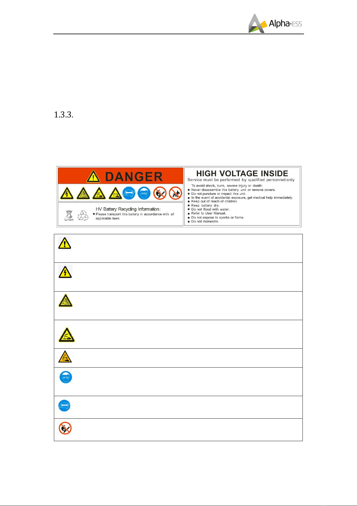
Protection of Warning Sign ........................................................................ 6
Setting of Warning Sign for Safety ............................................................. 7
Measuring Equipment ................................................................................ 7
Moisture Protection .................................................................................... 7
Operation After Power Failure ................................................................... 7
Battery Safety Datasheet ........................................................................... 7
General Precautions .......................................................................... 8
Parts List .......................................................................................... 10
Liability Limitation ........................................................................... 10
2. Installation ............................................................................................... 11
Installation Site and Environment ................................................... 11
General .................................................................................................... 11
Restricted Locations ................................................................................ 11
Barrier to habitable rooms ....................................................................... 12
Installation ........................................................................................ 13
3. Switch On/Off and Display .................................................................... 23
Switch On/Off ................................................................................... 23
LED Display ...................................................................................... 23

______________________________________________________________________
Alpha ESS Co., Ltd.
Page 4 of 31
Your Smart Energy
Content'
4. Error and Protection Code .................................................................... 24
Protection Code ............................................................................... 24
Error Code ........................................................................................ 25
5. Emergency Situations ........................................................................... 26
6. Warranty ................................................................................................. 27
Warranty ........................................................................................... 27
Limitation of Liability ...................................................................... 27
7. Routine Maintenance ............................................................................ 28
Maintenance Plan ............................................................................ 28
Operating Environment ............................................................................ 28
Equipment Cleaning ................................................................................ 28
Cable, Terminal and Equipment Inspection ............................................. 28
Notes ................................................................................................. 28

______________________________________________________________________
Alpha ESS Co., Ltd.
Page 5 of 31
Your Smart Energy
Introduction'
1. Introduction!
@-%$+.-#)
The eSTORE-BAT-10.3 battery pack has the following features:
Photovoltaic system: This battery pack is designed for household photovoltaic systems.
Battery management system (BMS): The battery packs built-in BMS monitors its operation
and prevents the battery from operating outside design limitations.
Expandability: This battery pack can be easily expanded by adding expansion battery packs.
1A-B'C'B%$'("#)
Figure 1.1 eSTORE-BAT-10.3 Appearance
1: LED Display
1%C-$/)!"$.(0+B$'(")
Manual&keeping&
This manual contains important information about operating the system. Before operating,
please read it very carefully.
The system should be operated in strict accordance with the description in the manual, in
case that it causes damages or loss to equipment, personnel and property.
This manual should be kept carefully for maintenance and reparation.
Operator&Requirements&
The operators should get a professional qualification, or trained.
1

______________________________________________________________________
Alpha ESS Co., Ltd.
Page 6 of 31
Your Smart Energy
Introduction'
The operators should be familiar with the whole storage system, including compositions
and working principles of the system.
The operators should be familiar with the Product Instruction.
While maintaining, the maintainer is not allowed to operate any equipment until all the
equipment has been turned off and fully discharged.
Protection&of&Warning&Sign&
The warning sign contains important information for the system to operate safely, and it is
strictly prohibited to be torn or damaged. Ensure that the warning sign is always clear. The
signs should be replaced immediately when damaged.
It indicates a hazardous situation which, if not avoided, could result in death or serious
injury!
Danger of high voltage and electric shock!
Do not punctur, impact, mutilate this unit or put it into the fire. It can lead explosion.
Please wash your hands after using the battery.
Warning: hazards due to batteries.
The installation and maintenance work should be handled with professional person/s,
who is/are knowlegeable about batteries.
Installation and maintenance reference to this installation and maintenance manual.
Do not expose to sparks or flame

______________________________________________________________________
Alpha ESS Co., Ltd.
Page 7 of 31
Your Smart Energy
Introduction'
Keep out of reach of children
The product must not be disposed of in household waste;
Dispose of it through environmentally friendly collection centres.
Setting&of&Warning&Sign&for&Safety&
While instructing, maintaining and repairing, in case of preventing unrelated personnel
nearby to cause incorrect operation or accident, the opinions below should be followed:
• Obvious signs should be set at front switch and rear-level switch in case of accidents
caused by false switching.
• Warning signs or tapes should be set near operating areas.
• The system must be reinstalled after maintenance or operation.
Measuring&Equipment&
For ensuring the electrical parameters to match requirements, related measuring
equipment are required when the system is being connected or tested.
Ensure that the connection and use matches specification in case of electric arc or shock.
Moisture&Protection&
It is very likely that moisture may cause damages to the system.
Repair or maintaining activities in wet weather should be avoided or limited.
Operation&After&Power&Failure&
The battery system belongs to energy storage system, and it keeps fatal high voltage even
the DC side is disconnected. Therefore, touching the output of the battery is strictly
prohibited.
The Inverter maintains fatal voltage even both the DC or AC side are disconnected, so it
must be tested by multimeter for safety before operation.
Battery&Safety&Datasheet&

______________________________________________________________________
Alpha ESS Co., Ltd.
Page 8 of 31
Your Smart Energy
Introduction'
1.3.8.1&Hazard&Information&
Classification of the hazardous chemical
Lithium Iron Battery is Exempt from classification according to Australian WHS regulations.
Other hazards
This product is a Lithium Iron Phosphate Battery with certified compliance under the UN
Recommendations on Transport of Dangerous Goods, Manual of Tests and Criteria, Part
III, sub-section 38.3. For the battery cell, chemical materials are stored in a hermetically
sealed metal case, designed to withstand temperatures and pressures encountered during
normal use. As a result, during normal use, there is no physical danger of ignition or
explosion and chemical danger of hazardous materials' leakage. However, if exposed to a
fire, added mechanical shocks, decomposed, added electric stress by misuse, the gas
release vent will be operated. The battery cell case will be breached at the extreme.
Hazardous materials may be released. Moreover, if heated strongly by the surrounding fire,
acrid or harmful fume may be emitted.
1.3.8.2&Safety&Datasheet&
The detailed information please refer to the provided battery safety datasheet, which is
provided with the battery product.
D-"-.%&)E.-B%+$'("#)
WARNING
Risk of chemical burns from electrolyte or toxic gases.
During standard operation, no electrolyte shall leak from the battery pack and no toxic gases shall
form. Despite careful construction, if the Battery Pack is damaged or a fault occurs, it is possible that
electrolyte may be leaked or toxic gases formed.
Ø Do not install the system in any environment of temperature below -10°C or over 50°C and
in which humidity is over 85%.
Ø Do not touch the system with wet hands.
Ø Do not put any heavy objects on top of the system.
Ø Do not damage the system with sharp objects.
Ø Do not install or operate the system in potentially explosive atmospheres or areas of high
humidity.

______________________________________________________________________
Alpha ESS Co., Ltd.
Page 9 of 31
Your Smart Energy
Introduction'
Ø Do not mount the inverter and the battery pack in areas containing highly flammable
materials or gases.
Ø If moisture has penetrated the system (e.g. due to a damaged enclosure), do not install or
operate the system.
Ø Do not move the system when it is already connected with battery modules.
Ø Secure the system to prevent tipping with restraining straps in your vehicle.
Ø The transportation of AlphaESS eSTORE-BAT-10.3 must be made by the manufacturer or
an instructed personal. These instructions shall be recorded and repeated.
Ø A certified ABC fire extinguisher with minimum capacity of 2kg must be carried along when
transporting.
Ø It is totally prohibited to smoke in the vehicle as well as close to the vehicle when loading
and unloading.
Ø For the exchange of a battery module, please request for new hazardous goods packaging
if needed, pack it and let it be picked up by the suppliers.
Ø In case of contact with electrolyte, rinse the affected areas immediately with water and
consult a doctor without delay.
CAUTION:
Risk of injury through lifting or dropping the system.
The battery is heavy. There is risk of injury if the battery is lifted incorrectly or dropped during transport
or when attaching to or removing from the wall.
Ø Lifting and transporting the inverter and battery must be carried out by more than 1 people.

______________________________________________________________________
Alpha ESS Co., Ltd.
Page 10 of 31
Your Smart Energy
Introduction'
E%.$#)F'#$)
F'%G'&'$/)F'H'$%$'(")
Any product damage or property loss caused by the following conditions AlphaESS does
not assume any direct or indirect liability.
• Product modified, design changed or parts replaced without AlphaESS
authorization;
• Changes, or attempted repairs and erasing of series number or seals by non
AlphaESS technician;
• System design and installation are not in compliance with standards and
regulations;
• Failure to comply with the local safety regulations (VDE for DE, SAA for AU);
• Transport damage (including painting scratch caused by rubbing inside
packaging during shipping). A claim should be made directly to shipping or
insurance company in this case as soon as the container/packaging is unloaded
and such damage is identified;
• Failure to follow any/all of the user manual, the installation guide and the
maintenance regulations;
• Improper use or misuse of the device;
• Insufficient ventilation of the device;
• The maintenance procedures relating to the product have not been followed to
an acceptable standard;
• Force majeure (violent or stormy weather, lightning, overvoltage, fire etc.);
• Damages caused by any external factors.
Battery Cable (1 pair)

______________________________________________________________________
Alpha ESS Co., Ltd.
Page 11 of 31
Your Smart Energy
Installation'
2. Installation!
This Manual introduces the basic steps how to install and operate AlphaESS eSTORE-
BAT-10.3
eSTORE-BAT-10.3 is a sealed component with no access to battery terminals or cell
components within module.
eSTORE-BAT-10.3 contains a Bi-pole DC isolator, which conforms to IEC 60947. It has
been operated in all live conductors
NOTE: please pay attention for unpacking the battery, the worst case
is that some components could be damaged.
!"#$%&&%$'(")1'$-)%"0)5"I'.("H-"$)
General&
The externals enclosure’s material is SPCC. The material thickness is 1.5 mm.
The eSTORE-BAT-10.3 can be installed in an outdoor or an indoor location.
In SN □□□-YYMMXXXX-PP on the packaging, PP for outdoor version will be 27.
Where battery systems are installed within a room, shall be located so that access to the
battery is not obstructed by the structure of the building, fixtures and fittings within the room.
eSTORE-BAT-10.3 adopts natural ventilation. The location should be clean, dry and
adequately ventilated. The room’s entry doors and panels shall open in the direction of
egress and allow unobstructed access to the battery for installation and maintenance
purposes.
The following location are not allowed for installation:
• habitable rooms;
• ceiling cavities or wall cavities;
• on roofs that are not specifically considered suitable;
• access / exit areas or under stairs / access walkways;
• where the freezing point can be reached, such as garages,
carports or other places as well
• as wet rooms (environmental category 2);
• locations with humidity and condensation over 85%;
• places where salty and humid air can penetrate;
• seismic areas - additional security measures are required;
• sites higher than 3000 meters above sea level;
• places with an explosive atmosphere;
• locations with direct sunlight or a large change in the ambient temperature;
600mm
600mm
1000mm
900mm

______________________________________________________________________
Alpha ESS Co., Ltd.
Page 12 of 31
Your Smart Energy
Installation'
• places with flammable materials or gases or an explosive atmosphere.
• places without clearance of right photo shows.
Restricted&Locations&
The battery system shall not be installed —
(a) in restricted locations, as defined for switchboards in AS/NZS 3000;
(b) within 600 mm of any hot source, such as water unit, gas heater, air conditioning unit
or any other appliance.
(c) within 600 mm of any exit;
(d) within 600 mm of any window or ventilation opening;
(e) within 900 mm of access to 240 Vac connections; and
(f) within 600 mm of side of other equipment.
An eSTORE-BAT-10.3 installed in any corridor, hallway, lobby or the like leading to a fire
exit shall ensure sufficient clearance from the ESTORE-BAT-10.3 for safe egress and no
less than 1 m.
An eSTORE-BAT-10.3 is considered a source of ignition and therefore shall not be installed
within hazardous area for gas cylinders containing heavier than air gasses and gas relief
vent terminal as defined in AS/NZS 3000.
Barrier&to&habitable&rooms&
To p r o t e c t a g a i n s t the s p r e a d o f fire t o h a b i t a b l e r o o ms, w h e r e t h e eSTORE-BAT-10.3 is
mounted on, placed against a surface of a wall or structure that has a habitable room on
the other side, the wall or structure shall be a suitably non-combustible barrier. If the
mounting surface itself is not made of a suitably non-combustible material, a non-
combustible barrier may be placed between the M4856-P and the surface of a wall or
structure.
Where the eSTORE-BAT-10.3 is located on or within 300mm of the wall or structure
separating it from the habitable room, the barrier shall extend —
(i) 600 mm beyond the vertical sides of the ESTORE-BAT-10.3;
(ii) 1200 mm above the ESTORE-BAT-10.3; and
(iii) to the extent of the bottom of the ESTORE-BAT-10.3
Where the top of the ESTORE-BAT-10.3 is within 1200 mm of the ceiling or structure above
the ESTORE-BAT-10.3, the ceiling or structure surface shall be suitably non-combustible
for an area of 600 mm past the extremities of the ESTORE-BAT-10.3.
ESTORE-BAT-10.3 shall be mounted with the highest point no greater than 2.2 m above

______________________________________________________________________
Alpha ESS Co., Ltd.
Page 13 of 31
Your Smart Energy
Installation'
the floor or platform.
!"#$%&&%$'(")
Step 1: open the battery package.
Note: The box must be placed in the direction of the label and only remove the
packaging in upwards direction. Removing the packaging in other directions is wrong.
Step 2: Fixed the bracket on the battery with M5*10 screws.

______________________________________________________________________
Alpha ESS Co., Ltd.
Page 14 of 31
Your Smart Energy
Installation'
Step 3: Insert the expansion tube into the drilled hole. Pass the expansion screw through
the gasket and lock with a screwdriver. Fixed the battery on the wall with M8*60 screws.
If there are more than two batteries, please skip to Step 24.
!
Step 4: Remove the Cable Box and remove the front panel.

______________________________________________________________________
Alpha ESS Co., Ltd.
Page 15 of 31
Your Smart Energy
Installation'
Step5. Remove the inverter and accessories.
Step6. Placed the cable box bracket on the battery and position it with 2 x M5*10
positioning screws.
Step7. Please drill four holes (two on each side) directly on the wall at the marking positions
of the bracket with an impact drill (bit φ 8.0 mm, length 60 cm) and the depth of each hole
should be about 7 cm. Fixed cable box bracket on the wall with 4 x M8*60 and 4 x M6
gaskets.
Step8. Remove the positioning screws.
Step9. Fixed the cable box on cable box bracket and lock the cable box with screws.

______________________________________________________________________
Alpha ESS Co., Ltd.
Page 16 of 31
Your Smart Energy
Installation'
Step10. Place the inverter bracket on the
cable box bracket and confirm the punch
position.
Step12. Mounting the inverter on the bracket.
Step11. Please drill four holes (two on each
side) directly on the wall at the marking
positions of the bracket with an impact drill
(bit φ 8.0 mm, length 60 cm) and the depth
of each hole should be about 7 cm.
Step13. Fixed the inverter, customers can
install locks according to your needs.
Step14. Install the Wi-Fi module and secure it with 2 x M5*10 screws.
Note: Wi-Fi module should be installed on the left side of the inverter bracket.

______________________________________________________________________
Alpha ESS Co., Ltd.
Page 17 of 31
Your Smart Energy
Installation'
Step15. In order to remain the earth continuity on battery, please following the procedure
below for earthing
Step16. Use a screwdriver to remove the right communication panel.
Step17. The battery DIP switch is configured according to the black mark position shown
in the figure below. That is, for the farthest battery from the inverter, the DIP switch 2 and
3 of the battery is on, and the other numbered battery DIP switches are all downwards.

______________________________________________________________________
Alpha ESS Co., Ltd.
Page 18 of 31
Your Smart Energy
Installation'
Step18. Pass the communication cable through the cable gland and pass it into the
communication port of the battery.
Step19. Fixed the connector of the cable box power Cable to the inverter with 2 x M8*12
screws.
Note: Make sure the power cable passes through the cable gland and the terminal
color is required, Fixed with 4 x M3*8 screws.
Step 20. Install the power plugs between the battery and the cable box.
Note: Ensure that the color should be correct and the power plugs should be plugged
correctly.
Table of contents
Other Alpha ESS Camera Accessories manuals