Alpha MED Scientific MED64 User manual

Operating Instructions
MED64
Integrated Amplifier
P/N: SU-MED640P
An advanced and easy-to-use solution
for in-vitro Electrophysiology

Safety Precautions
Before using this unit please read these operating instructions carefully. Take special care to follow the
warnings indicated on the unit itself as well as the safety suggestions listed below. Keep these precau-
tions handy for future reference.
The unit may be used only in the operating conditions and positions specified manufacturer.
Unless otherwise agreed the following applies to this unit.
1. Pollution category: II (Indoor use only)
2. Installation over voltage category: II
3. Altitude: max.2,000 m
Placement
Avoid placing the unit in areas of:
- direct sunlight
- high temperature
- high humidity
- excessive vibration
- uneven surfaces (Place the unit on a flat level surface.)
Such conditions might damage the cabinet and/or other component parts and thereby shorten the unit's
service life.
Stacking
Never place heavy items on top of the unit or the AC power cord.
Voltage
- It is very dangerous to use a “high voltage” AC power source such as for an air conditioner. A fire might
be caused by such a connection.
- A DC power source can not be used. Be sure to check the power source carefully.
Power cord protection
- Avoid using AC power cords with cuts, scratches, or poor connectors, as this may result in fire or electric
shock. Excessive bending, pulling or slicing of the cord should also be avoided.
- Do not pull on the cord when you are disconnecting the power, as this could cause an electric shock.
Grasp the plug firmly when you disconnect the power supply.
- Never touch the plug with wet hands or a serious electric shock could result.
Foreign Materials
- Ensure that no foreign objects (e.g. - needles, coins, screwdrivers), accidentally fall into the unit. Other-
wise, a serious electric shock or malfunction could occur.
- Be extremely careful about spilling water or liquid on or into the unit, as a fire or electric shock could
occur (Disconnect the power plug and contact your dealer immediately if this occurs).
- Avoid spraying volatile chemicals (e.g.- insecticides, alcohol, paint thinner) on or into the unit as they
contain flammable gases which can be ignited.
- Insecticides, alcohol, paint thinner and similar chemicals should never be used to clean the unit as they
can cause flaking or cloudiness to the cabinet finish.

3
Service
- Never attempt to repair, disassemble or modify the unit if there seems to be a problem. A serious electric
shock could result if you ignore this precautionary measure.
- If a problem occurs during operation (smoke is detected, etc.) contact your dealer immediately.
- Disconnect the power supply if the unit will not be used for a long time. Otherwise the operation life could
be shortened.
Safety-related symbols used on equipment and documentation:
Environmental conditions
- Indoor use.
- Altitude up to 2000 m.
- Temperature: 5 - 40 C.
- Maximum relative humidity 80% for temperatures up to 31 C decreasing linearly to 50% relative humidity
at 40 C.
- Mains supply voltage fluctuations not to exceed +/- 10% of the nominal voltage.
Maintenance
Clean the cabinet, panel and controls with a soft cloth lightly moistened with mild detergent solution.
Do not use any type of abrasive pad, scouring power or solvent such as alcohol or benzine.
Fuse (F1)
Rating: 125 V, 630 mA
Frame or chassis
TERMINAL

4
Components and their functions
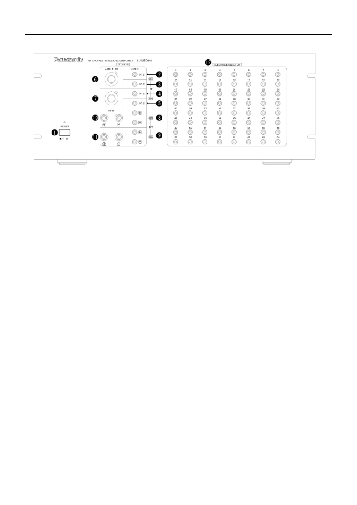
Front panel
(1) POWER
To turn the amplifier on and off.
Caution: Do NOT turn on the power with a stimulation cord connected on the output terminal of the internal stim-
ulators (#2, 3, 4 & 5). This may cause damage to the microelectrode(s) on the probe.
(2) OUTPUT INT(V) [CH1]
The output terminal for the variable, internal channel 1 (CH1) constant current stimulator. The amplitude of the
current delivered is variable (V) and can be adjusted with dial (6)*1.
(3) OUTPUT INT(F) [CH1]
The output terminal for the fixed, internal channel 1 (CH1) constant current stimulator. The amplitude of the cur-
rent delivered is fixed (F) and set on the computer*1.
(4) OUTPUT INT (V) [CH2]
The output terminal for the variable, internal channel 2 (CH2) constant current stimulator. The amplitude of the
current delivered is variable (V) and can be adjusted with dial (7)*1.
(5) OUTPUT INT(F) [CH2]
The output terminal for the fixed, internal channel 2 (CH2) constant current stimulator. The amplitude of the cur-
rent delivered is fixed (F) and set on the computer*1.
(6) AMPLITUDE [CH1]
This 'potentiometer' is used to adjust the output amplitude for the variable, CH1 stimulator (2). The initial
(x1)amplitude, which is set in the computer software, can be adjusted in 0.1 steps between 0 and 10 times.
(7) AMPLITUDE [CH2]
This 'potentiometer' is used to adjust the output amplitude for the variable, CH2 stimulator (4). The initial
(x1)amplitude, which is set in the computer software, can be adjusted in 0.1 steps between 0 and 10 times.
(8) OUTPUT EXT [CH3]
The output terminal for an external stimulus isolation unit (see page 4)*2,*3.
(9) OUTPUT EXT [CH4]
The output terminal for an external stimulus isolation unit (see page 4)*2,*3.
(10) INPUT EXT [CH3]
The input terminals (+ & -) for an external stimulus isolation unit.
(11) INPUT EXT [CH4]
The input terminals (+ & -) for an external stimulus isolation unit.
(12) ELECTRODE SELECTOR
The terminal(s) used to select the stimulus electrodes on the MED probe. Use a MED64 stimultion cord to con-
nect to either terminals (2) through (5) or terminals (8) and (9).
*1 The internal stimulus amplifier in this unit delivers constant current pulses between the electrode selected with
ELECTRODE SELECTOR (12) and the reference electrodes (see page 5).
*2 The external stimulus isolation unit(s) can be used to deliver monopolar pulses (mono-phasic or bi-phasic) pulses
between one of the 64 electrodes and the reference electrodes (as is the case for the internal stimulators). In this
scenario, the MED64 stimulation cord is connected between the + or - output terminal and one probe electrode of
your choice using the Electrode Selector panel (12).
*3 The external stimulus isolation unit(s) can also be used to deliver true bipolar pulses between 2 electrodes of your
choice from the 64 available points.

5
Back Panel
(13) INPUT
For connecting to the MED probe, through the MED-CO3 connector, to the amplifier.
(14) OUTPUT(1-32CH)
For connecting the output of channels 1-32 to the to the first A/D board in the computer.
(15) OUTPUT(33-64CH)
For connecting the output of channels 33-64 to the to the second A/D board in the computer.
(16) SIGNAL OUTPUT
BNC connectors used to send analog outputs from selected recording channels to an external amplifier, signal
processor, or other device (e.g. - oscilloscope).
(17) STIMULUS EXT 1
For connecting to an external stimulus isolation unit. Outputs the EXT 1 trigger pulse from the computer to the
external stimulator.
(18) STIMULUS EXT 2
For connecting to an external stimulus isolation unit. Outputs the EXT 2 trigger pulse from the computer to the
external stimulator.
(19) OPERATION IN
Input port for signals from exernal components.
(20) OPERATION OUT
Output port for signals to the external components.
(21) SIGNAL GND
A ground terminal for signals.
(22) ~ AC IN
Insert the AC power supply cord here.
Reference Electrodes
To optimize the signals from all 64 electrodes as recording/stimulating electrodes, reference electrodes
have been added. This allows differential recording to be made between each channel and reference
electrodes. It also optimizes the delivery of mono-polar stimuli, as they are delivered between the chosen
(recording) electrode and the reference electrodes.
MED probe Reference electrodes

6
Connection to other components
Usage of internal stimulus amplifier
(Components and cables indicated with dashed lines are not included)
MED Connector
A/D board cables
(NI SH-100100)
Connector cable (included)
A/D board in PC
(NI PCI-6071E) A/D board in PC
(NI PCI-6071E)

7
Using the MED64 amplifier with External Devices (stimulator, isolator,
oscilloscope).
Caution: Do NOT connect MED64 stimulation cord on the internal stimulator outputs (CH1 or CH2).
(Components and cables indicated with dashed lines are not included.)
External Stimulator
External Isolator
External Stimulator
External Isolator
BNC cables
BNC cables
BNC cables
A/D board cables
(NI SH-100100)
A/D board in PC
(NI PCI-6071E) A/D board in PC
(NI PCI-6071E)
MED Connector
Connector cable (included)
Oscilloscope

8
Precautions during use
Always, turn ON the amplifier power BEFORE starting up the software. The software sends information to
the amplifier for initialization of the internal stimulators and other features (e.g. filtering) necessary for
accurate recording of data. Failure to do so (i.e. turning ON power to the amplifier after the software starts
up) will lead to inaccuracies in stimulus delivery and the data recorded.
Included accessories
Warranty
This product will be repaired with new or refurbished parts, free of charge, for one (1) year from the date
original purchase in the event of a defect in materials or workmanship.
The product warranty covers failures due to defects in materials or workmanship which occur during nor-
mal use. It does NOT cover damage which occurs in shipment or failures which are caused by products
not supplied by Alpha MED Sciences. In addition, this warranty does not cover failures resulting with
results from alteration, accident, misuse, neglect, faulty installation, maladjustment of user controls,
improper maintenance, modifications or service by anyone other than AMS or damage that is attributable
to acts of God.
Please refer attached warranty card in detail.
Power supply cord (1 pc.) Connector cable (1 pc.)
Stimulation cord(4 pcs.)

9
Specifications
Specifications may not be satisfied depending upon the type of computer or operating environments used.
Only for use in animal studies research.
Specifications and external appearance are subject to change without notice.
[Recording unit]
Channels 64
Input impedance 100 MΩ
Maximum output voltage +/- 12 Vp
Output impedance 2.2 kΩ
Amplification x 1000 (60 dB)
Low-cut filter
(PC control, Stimulation 64 CH switch) 0.1, 1, 10 and 100 Hz
(4 settings, 12 dB/oct)
Frequency range (low-cut: 0.1 Hz) 0.1 Hz to 10 kHz (+0 dB to -3 dB)
Residual noise < 4 mV (input; shor circuit)
[Stimulus unit]
Output format Constant current
Channels
with variable dial (V) 2
without variable dial (F) 2
Amplification adjustment 0 to 10 times (in 0.1 steps)
Maximum output voltage +/- 12 Vp
Maximum output amplitude
with variable dial (V) +/- 2 mAp
without variable dial (F) +/- 2 mAp
[General]
Power requirement AC 120V, 60 Hz
Power consumption 33 W
Weight 13.0 kg
Dimensions W 483 x H 186 x D 430 mm

December, 2009
Alpha MED Scientific Inc.
209 Saito-incubator
7-7-15, Saito-asagi, Ibaraki Osaka,
567-0085, Japan
Phone: +81-72-648-7973
http://www.med64.com
support@med64.com
Manufactured by Alpha MED Scientific Inc.
U.S. Patents: 5,563,067 Oct. 1996. 5,810,725
Sept. 1998. 6,132,683 Oct. 2000.6,151,519 Nov.
2000.
©2009 Alpha MED Scientific Inc.
Other manuals for MED64
1
Table of contents
Other Alpha MED Scientific Amplifier manuals
Popular Amplifier manuals by other brands

Xtant
Xtant 2200ix Installer's guide

Stanford Research Systems
Stanford Research Systems SR865A Operation manual

YAMAMOTO
YAMAMOTO A08-S user manual

Pro-Ject Audio Systems
Pro-Ject Audio Systems Pro-Ject Audio Systems Instructions for use

Wet Sounds
Wet Sounds HT-1 owner's manual

Denon
Denon POA-3012CI - Multi-Zone Audio Distribution Power... Dimensions