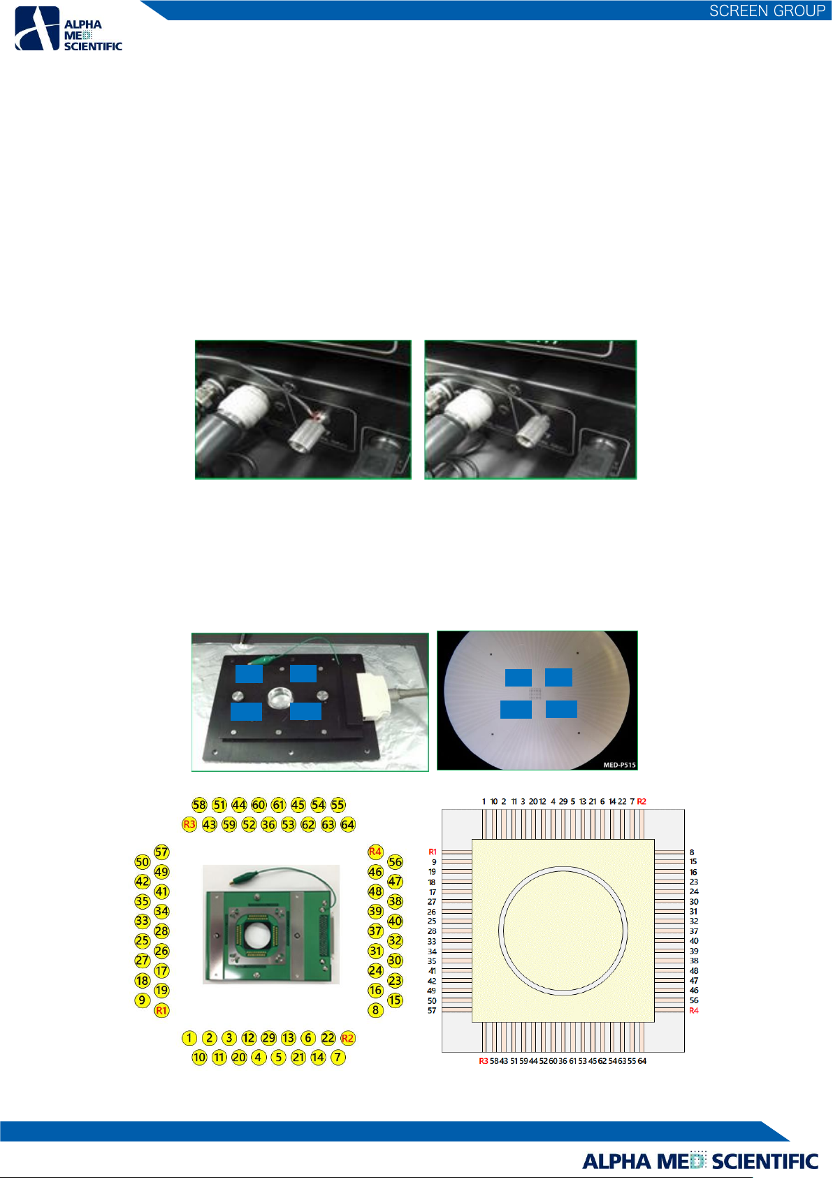
➊INPUT 1-16CH、17-32CH、33-48CH、49-64CH
….. Analog input terminals to input signal from the MED Duet Connectors or the MED Multi-well Connector. Those are connected
to the output terminals of the either via the 20-pin SCSI cable. Keep ➋INPUT opened (unconnected) when connecting the
cables (Do not connect at the same time.)
➋INPUT ….. An analog input terminal to input signal from the MED Connector. It is connected to the output terminal of the MED
Connector via the 68-pin SCSI cable. Keep the all ➊INPUT opened (unconnected) when connecting the cables (Do
not connect at the same time.)
➌OUTPUT ….. An analog output terminal to connect the INPUT terminal of the MED64 Main Amplifier via the 68-pin SCSI cable.
➍F1 STIMULUS INPUT ….. An input terminal of stimulus pattern signal to connect the F1 STIMULUS OUTPUT of the MED64 Main
Amplifier via the BNC cable.
➎F2 STIMULUS INPUT ….. An input terminal of stimulus pattern signal to connect the F2 STIMULUS OUTPUT of the MED64 Main
Amplifier via the BNC cable.
➏CONTROL INPUT ….. An input terminal of stimulation channel signal. It is connected to CONTROL OUTPUT of the MED64 Main
Amplifier via the round-pin cable.
➐SIGNAL GND ….. A ground terminal to connect a lead for grounding.
➑DC INPUT ….. To connect to a power adaptor cord.
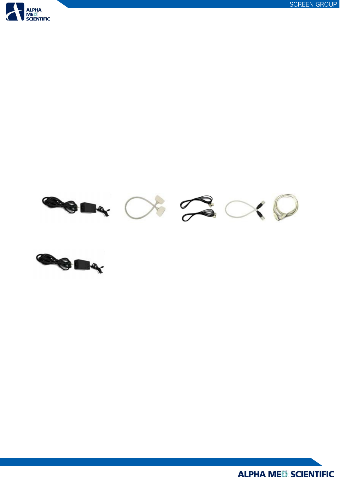
2.1.3. Accessories of the MED64 Main Amplifier
➊Power adaptor ➋68-pin SCSI cable (50cm) ➌BNC cable ➍Round-pin cable ➎USB cable
2.1.4. Accessories of the MED64 Head Amplifier
➊Power adaptor
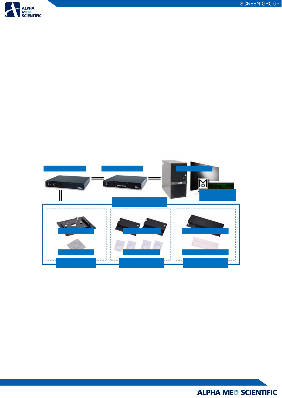
3. Setup of the MED64 System - procedure common to Basic, Quad II, and Allegro
Thanks to the excellent electrode impedance (impedance of 50 µm electrode is 10 kΩ in frequency range 1 kHz) of the MED Probe,
which is the sensor of the MED64 System, the MED64 System offers several technological advantages:
1) Less influence by external noise (hum noise, etc.)
2) Very low Johnson noise (baseline noise) at about several µV
3) The MED Probe/Connector can be installed at a place physically distant from the amplifier (e.g., inside of an incubator with
100% humidity) via a 2 m connection cable, without being affected by noise or attenuation of the signal acquired.
A faraday cage or vibration isolation table that is typically necessary for an electrophysiological experiment is not necessary for the
MED64 System, but the MED64 System should be set up on a stable table without vibrations, such as a laboratory desk. A desk of
about 100 cm width and 75 cm depth is necessary. For the user’s convenience, a larger desk is preferable. The power adaptor
connected to the amplifier, etc., serves as a magnetic field-derived noise source. When the MED64 System is set up on a desk
against a wall, make space for the cord between the wall and the desk and place the adaptor on the floor in order to place the
power adaptor at a distance from the amplifier and other components (the desk must not be fixed to the wall). Alternatively, a space
is necessary to ensure sufficient distance between the MED64 System and the power adaptor.