Alpha Professional Tools HEPA HWD1120 User manual

Part No: HWD1120/HWD1240
Version 1
Alpha®HEPA Wet/Dry
Vacuum Manual
MANUAL

2
TABLE OF CONTENTS
Introduction...................................................................................................... 3
About the Symbols .......................................................................................... 3
General Safety Instructions ............................................................................. 4
Safety Instructions for Electric Tools................................................................ 5
Grounding Instructions .................................................................................... 7
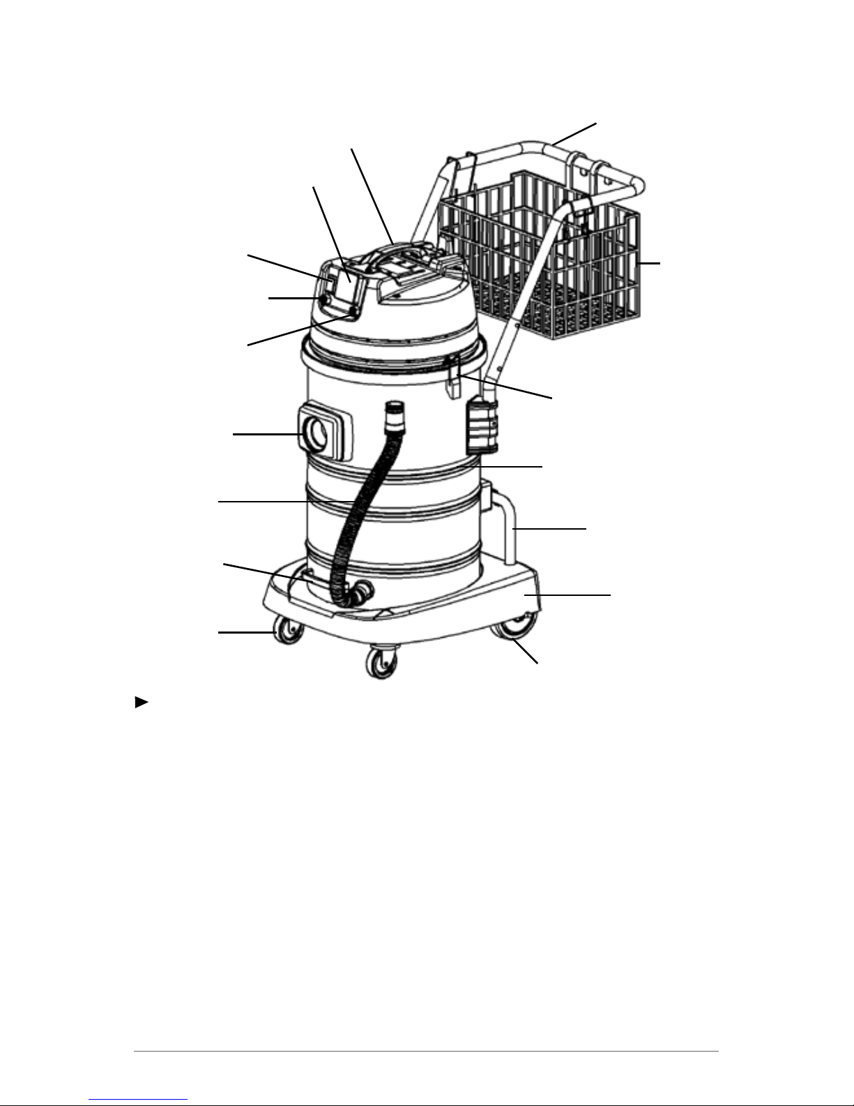
HEPA Wet/Dry Vacuum Overview ................................................................... 8
Specications............................................................................................ 8
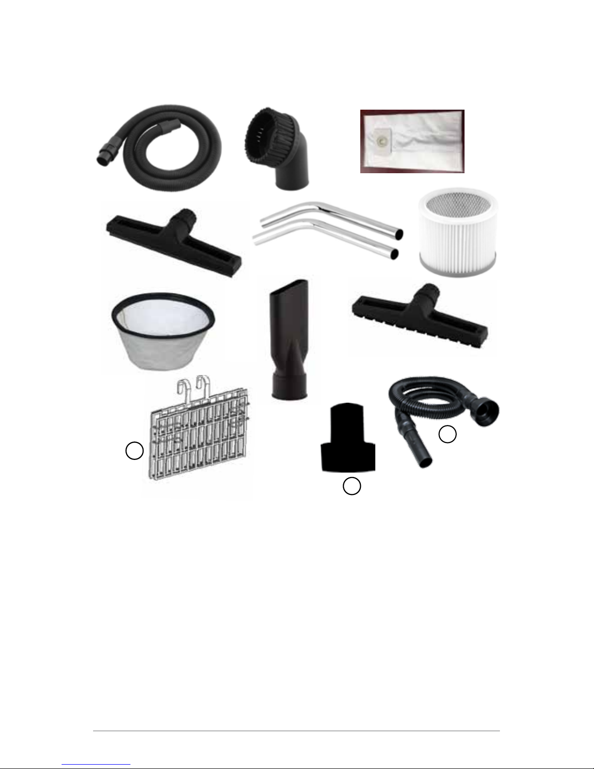
HEPA Wet/Dry Vacuum Accessories ............................................................... 9
Components.............................................................................................. 9
Additional Safety Instructions ........................................................................ 10
Operating Method.......................................................................................... 12
Connection.............................................................................................. 12
Operation - Electric Tool.......................................................................... 13
Operation - Pneumatic Tools................................................................... 13
Adjusting Handrail Height........................................................................ 14
Connecting the Alpha®Ecoguards .......................................................... 14
Connecting to Palm Sanders, Gear Action Sanders
and Sanding Blocks ................................................................................ 15
Setting up the Vacuum for Wet Use ........................................................ 16
Automatic Suction Shut Off ........................................................................... 17
Emptying Liquid from the Tank ...................................................................... 17
Maintenance.................................................................................................. 18
Attaching the Storage Basket........................................................................ 19
Alpha®HEPA Wet/Dry Vacuum Schematic (Inside)....................................... 21
Alpha®HEPA Wet/Dry Vacuum Schematic (Outside).................................... 22
Alpha®HEPA Wet/Dry Vacuum Parts List...................................................... 23
Accessories and Factory Service .................................................................. 26
Warranty ........................................................................................................ 26
Product Registration...................................................................................... 27

3
INTRODUCTION
Thank you for purchasing an Alpha®HEPA Wet/Dry Vacuum for Pneumatic and
Power Tools. This vacuum cleaner is a high-quality, precision made product. All
parts used in the manufacturing of this vacuum cleaner have passed rigid quality
controlstandardspriortoassemblyandan“eachunit”nalinspectionpriorto
packaging is your assurance of proper assembly. This vacuum cleaner was
protectively packaged to prevent possible damage in transit. Should damage occur,
please notify the transporting carrier immediately for loss and/or claim.
ABOUT THE SYMBOLS
Accordingtothehazardlevel,allsafetynotesinthismanualareclassiedinto
“DANGER”, “WARNING”, and “CAUTION”.
DANGER! Death or serious personal injury is imminent when handling
this vacuum incorrectly.
WARNING! There is a possibility of death or serious personal injury
when handling this vacuum incorrectly.
CAUTION! There is a possibility of personal injury or property damage
when handling this vacuum incorrectly.
Note: In some situations, failing to observe WARNING notes
could result in death or serious personal injury. Be sure
to read and observe the safety notes to ensure safety
and correct use of the polisher.

4
GENERAL SAFETY INSTRUCTIONS
When using an electrical appliance, basic precaution should always be
followed, including the following:
READ ALL INSTRUCTIONS
BEFORE USING THIS VACUUM CLEANER
WARNING
To reduce the risk of re, electric shock or injury:
1. Do not leave appliance when plugged in. Unplug from outlet when not in use
and before servicing.
2. Do not expose to rain. Store indoors.
3. Do not allow to be used as a toy. Close attention is necessary when used by
or near children.
4. Use only as described in this manual. Use only manufacturer’s recommended
attachments.
5. Do not use with damaged cord or plug. If appliance is not working as it should,
has been dropped, damaged, left outdoors, or dropped into water, contact the
Alpha®Tool Department.
6. Do not pull or carry by cord, use as a handle, close a door on cord, or pull cord
around sharp edges or corners. Do not run appliances over cord. Keep cord
away from heated surfaces.
7. Do not unplug by pulling on cord. To unplug, grasp the plug, not the cord.
8. Do not handle plug or appliance with wet hands.
9. Do not put any object into openings. Do not use with any opening blocked;
keepfreeofdust,lint,hairandanythingthatmayreduceairow.
10. Keephair,looseclothing,ngersandallpartsofthebodyawayfromopenings
and moving parts.

5
11. Do not pick up anything that is burning or smoking, such as cigarettes, matches,
or hot ashes.
12. Donotusedrywithoutdustbagand/orltersinplace.
13. Turn off all controls before unplugging.
14. Use extra care when cleaning on stairs.
15. Donotusetopickupammableorcombustibleliquidssuchasgasoline,or
use in areas where they may be present.
16. This vacuum is for commercial use only.
17. Connect to a properly grounded outlet only. See grounding instructions.
SAVE THESE INSTRUCTIONS
SAFETY INSTRUCTIONS FOR ELECTRIC TOOLS
1. KNOW YOUR POWER TOOL. Read owner’s manual carefully.
Learnitsapplicationsandlimitationsaswellasspecicpotentialhazards
particular to this tool.
2. KEEP WORK AREA CLEAN. Cluttered areas invite accidents. Do
not put any object into openings. Do not use with any opening blocked; keep
freeofdust,lint,hairandanythingthatmayreduceairow
3. AVOID DANGEROUS ENVIRONMENTS. Do not use tool in
presenceofammableliquidsorgases.Keeptheareawelllit.
4. KEEP CHILDREN AND VISITORS AWAY. All visitors should be
kept a safe distance from the work area. Keep out of reach of children.
5. DON’T FORCE TOOL. It will do the job better and safer at the rate
for which it was designed.
6. WEAR PROPER APPAREL. Do not wear loose clothing or jewelry
as it can get caught in moving parts. Rubber gloves and insulated non-skid
footwear are recommended. Wear protective covering to contain long hair.

6
7. WEAR PROPER EYE PROTECTION. Use safety glasses at all
times. Also, use a face mask if work area is dusty.
8. DON’T OVERREACH. Keep proper footing and balance at all times.
9. DISCONNECT TOOLS WHEN NOT IN USE. Always disconnect
tool before servicing; when changing accessories such as grinding wheels,
backer pads, etc.
10. MAINTAIN TOOLS WITH CARE. Keep tools clean at all times
for best and safest performance. Follow instructions for lubricating and
changing accessories. Keep handles dry, clean and free of oil or grease.
Inspect moving parts for alignment and binding as well as for breakage and
improper mounting.
11. AVOID ACCIDENTAL STARTING. Don’t carry a “connected” tool,
or make adjustments, or change discs without making sure the air valve is
intheoffpositiontopreventtheowofair.
12. USE ONLY RECOMMENDED ACCESSORIES. The use of any
accessories other than what is listed or recommended for this particular
tool may be hazardous.
13. KEEP HANDS AWAY FROM ALL MOVING PARTS.
14. STAY ALERT. Watch what you are doing and use common sense. Do
notoperatetoolwhenyouaretired,orundertheinuenceofmedication
or alcohol.

7
GROUNDING INSTRUCTIONS
This appliance must be grounded. If it should malfunction or breakdown, ground-
ing provides a path of least resistance for electric current to reduce the risk of
electric shock. This appliance is equipped with a cord having equipment ground-
ing conductor and grounding plug. The plug must be inserted into an appropriate
outlet that is properly installed and grounded in accordance with all local codes
and ordinances.
This appliance is for use on a nominal 120/240 Volt circuit, and has a grounded
plug that looks like the plug illustrated in sketch A below. A temporary adapter that
looks like the adapter illustrated in sketches B and C may be used to connect this
plug to a 2-pole receptacle as shown in sketch B if a properly grounded recep-
tacle is not available. The temporary adapter should be used only until a properly
groundedoutlet(sketchA)canbeinstalledbyaqualiedelectrician.Thegreen
colored ear, lug, or the like extending from the adapter must be connected to a
permanent ground such as a properly grounded outlet box cover.
Whenever the adapter is used, it must be held in place by a metal screw.
NOTE: In Canada, the use of a temporary adapter is not permitted by the Canadian
Electrical Code.

8
HEPA WET/DRY VACUUM OVERVIEW
Handrail
Storage
Basket
Tank Clip
Tilt/Dump
Support Shelf
Pedestal
Back Wheels
Front
Wheels
Tank Handle
Drain Hose
Suction Inlet
Air-In Connector
Air-Out Connector
Switch
Electrical
Outlet
Handle
Stainless
Steel Tank
SPECIFICATIONS
Model.............................................................................HWD1120 / HWD1240
Capacity ............................................................................15 Gallon / 60 Liters
Rating........................................................................................ 120 / 240 Volts
Amperage................................................................................................. 10 / 5
Frequency ..................................................................................... 50Hz - 60Hz
Power .....................................................................................................1200W
Weight ..................................................................................... 34 lbs / 15.5 kgs
Cord Length....................................................................................... 50ft / 15m
Hose Diameter ...........................................................1.5in x 10ft / 38mm x 3m
Tank Diameter .......................................................................... 13.75” / 350mm
Air Flow Rate.........................................................................................95 CFM
Water Lift ...................................................................................................... 80”

9
HEPA WET/DRY VACUUM ACCESSORIES
COMPONENTS:
1. Hose Assembly 1-1/2” x 10’ (Part No. HWD5004)
2. Round Brush (Part No. HWD5006)
3. Cloth Dust Bag (Part No. HWD5085)
4. Wet Floor Nozzle (Part No. HWD5009)
5. Metal Wand (Part No. HWD5005)
6. Hepa Filter (Part No. HWD5002)
7. Cloth Filter (Part No. HWD5001)
8. Crevice Nozzle (Part No. HWD5007)
9. Dry Floor Nozzle (Part No. HWD5008)
10. Hose Adapter (Part No. HEP110021)
11. Storage Basket (Part No. HWD5052)
12. Flexible Connector Hose 54” (Part No. 500073)
11
10
12

10
ADDITIONAL SAFETY INSTRUCTIONS
1. Beforeoperation,checkthatthelocalpowersupplyissameasthespecica-
tion on the rating label.
2. Do not use the machine in a combustible and explosive place in case the motor
sparksandcausesare.
3. Do not force items into the Air Hose Inlet mouth,
as it may cause the temperature to rise and
damage the motor.
4. Do not vacuum up combustible and/or explosive
objects, such as a glowing cigarette, gasoline,
etc.
5. Do not vacuum up sharp objects.
6. Do not vacuum up objects which can easily at-
tachontotheltersuchaslimeorchalkthatwill
block the ventilation and damage motor.

11
7. Always turn off the machine and
remove the plug when repairing or
after each use.
8. Do not overturn the machine to avoid
water from going into the motor and
damaging it.
9. Keep machine away from
strong sunlight and high
temperature places to avoid
the plastic distorting.
10. Do not rest, trample, or drag hose to avoid damaging it.
11. Do not immerse the tank cap into the water, or wash with water, to avoid water,
going into the electrical parts and causing personal injury. The correct way
should be, to immerse the dishcloth then squeeze dry. Wipe the dirty part gently.

12
OPERATION METHOD
CONNECTION
1. Insert the hose connector into the suction
inlet as shown in Figure 1, make sure the
connector is tightly fastened.
2. Press the connector button as shown in
Figure 2 and pull the connector out when
you want to disconnect from the machine.
3. Connect accessories as shown in Figure 3.
Connector
Button Figure 1
Figure 2
Figure 3
Round Brush

13
NOTE: When tools are turned on in the Auto Start mode, the
vacuum cleaner will delay for 3-4 seconds before turning on.
NOTE: When tools are turned off, the vacuum cleaner will
remain on 8-9 seconds to ensure all of the dust is suctioned from
the hose.
OPERATION - ELECTRIC POWER TOOL
1. Plug the vacuum power cord into the wall socket.
2. Insert the power tools plug into the supply socket on the vacuum.
3. Press the switch button on the vacuum to the appropriate location
desired.
• “I ” stands for turn on (Vacuum Suction Only), the socket has no
power.
• “ O” stands for turn off, the socket has no power.
• “ II ” stands for AUTO start and the vacuum will not turn on until the
Power tool starts working. The electrical socket has power in this
mode.
OPERATION - PNEUMATIC TOOL
1. Plug the vacuum power cord into the wall socket.
2. Attach the shops pneumatic hose line into the “AIR-IN” connector on the
vacuum.
3. Insert the pneumatic tools air supply hose into the “AIR-OUT” connector
on the vacuum.
NOTE: Couplers are not supplied with the vacuum but are
available as an optional accessory.
4. Press the switch button on the vacuum to the appropriate location
desired.
• “I ” stands for turn on (Vacuum Suction Only), the socket has no
power.
• “ O” stands for turn off, the socket has no power.
• “ II ” stands for AUTO start and the vacuum will not turn on until the
Pneumatic tool starts working. The electrical socket has power in
this mode.

14
According to your requirements, the
height of the handrail can be adjusted.
Press the buttons on both sides of the
handrail to raise or lower.
ADJUSTING HANDRAIL HEIGHT
CONNECTING THE ALPHA®ECOGUARDS
54”

15
CONNECTING TO PALM SANDERS, GEAR ACTION
SANDERS AND SANDING BLOCKS
1. Insert the Alpha®Dust Exhaust Hose (Part No. VH91100 / Sold Separately)
“cone” shape end into the opening of the Hose Assembly (Part No.
HWD5004).
NOTE: The Alpha®Dust Exhaust Hose has a 3/4” diameter
hose for attaching onto Palm and Gear Action Sanders.
Alpha® Dust Exhaust Hose
(Part No.VH91100)
Hose Assembly
(Part No. HWD5004)
Figure 4
Figure 5

16
The vacuum can be used for wet pick-up. Remove ALL dirt and
debris found in the tank to avoid contamination into the motor unit.
Remove the HEPA FILTER, CLOTH FILTER and CLOTH DUST BAG
prior to using the vacuum for wet pick-up.
SETTING UP THE VACUUM FOR WET USE
1. Remove the HEPA FILTER completely off the PEDESTAL BASKET by pulling
it downward. (See Figure 6)
2. Remove the Cloth Filter (Part No. HWD5001)
(See Figure 7)
3. Remove the Dust Cloth Bag (Part No. HWD5003)
(See Figure 8)
Figure 6
Figure 7
Figure 8

17
AUTOMATIC SUCTION SHUT-OFF
The vacuum is equipped with an automatic suction shut-off that
operates when picking up liquids. As the level of the liquid rises in
the tank, an internal oat rises until it seats itself against a seal at the
intake of the motor, shutting off suction (Figure 9). When this happens,
the motor will develop a higher than normal pitch noise and the suction
is drastically reduced. If this occurs, turn the unit off immediately.
EMPTYING LIQUID FROM THE TANK
1. Remove liquid from the tank by using the DRAIN HOSE.
2. Detach the DRAIN HOSE from the clip on the outside of the tank. (See Figure
10)
3. Remove the stopper plug on top of the DRAIN HOSE (See Figure 11).
4. PlacetheDRAINHOSEnexttotheoordrainandlettheliquidemptyfrom
the tank.
5. Once the tank is empty, reattach the stopper plug and clip the DRAIN HOSE
to the side of the tank.
Internal
Float
Figure 9
Figure 10 Figure 11

18
MAINTENANCE
1. Tank Cleaning – DRY USE
After working or when the cloth dust bag is full, it is recommended to clean
the tank to remove any dust or debris. This dust or debris could decrease the
suction considerably. Prior to cleaning the tank, disconnect the power from
the motor.
• Release the Tank Clips securing the motor assembly and remove the motor.
• Remove the HEPA Filter and blow off
• Remove the Cloth Filter and blow off
• Remove the Cloth Dust Bag and replace with
a new one
2. HEPA Filter Cleaning
• The HEPA Filter can be washed by using
clean, warm water.
• The HEPA Filter can also be cleaned by blow-
ing with compressed air.
• Allow the HEPA Filter to fully dry before using.
3. Tank Cleaning - WET USE
• After soaking up dirty water it is recommended that you should clean the
tank after use.
• Release the Tank Clips securing the motor assembly and remove the motor.
• Move the Tilt/Lock Knobs to the lower position to enable the tank to tilt back
and spray (Figure 13)
• Spray inside of the tank with a water hose to remove any debris (Figure 14).
When the Tilt/Lock Knobs
are in the “UP” position,
they tighten against the
Tilt/Dump Support Shelf
to secure the Stainless
Steel Tank.
Putting the Tilt/Lock Knobs in the “DOWN”
position allows the Stainless Steel Tank to
tip backwards on the Tilt/Dump Support
Shelf for easier cleaning.
NOTE: Make sure that the motor is
removed prior to tipping the tank
backwards.
Figure 12
Figure 13 Figure 14

19
Release the clip holding the Storage
Basket closed
ATTACHING THE STORAGE BASKET
NOTE: This foldable metal wire storage basket utilizes release
tab springs to hold the basket into the open position. Carefully
follow the steps listed below to fully open this storage basket.
1. Release the clip holding the foldable storage basket together making sure to
hold the storage basket down with your other hand.
2. Raise each section of the Storage Basket in the following order while you
continuously hold down the rest of the basket walls.
NOTE: Do not exceed the recommended maximum storage weight of 11lbs
(5kg) inorder to prevent vacuum cleaner from tumbling over.
STEP 1
STEP 3
STEP 2
STEP 4
Figure 15
Figure 16
Figure 18
Figure 17
Figure 19

20
3. Place the side hanging support brackets (x2) on each side of the basket as
shown below.
4. Place the back support bracket of the Storage Basket on the Handrail of the
vacuum as shown below.
5. Place the side support brackets on each side of the vacuums handrail as shown
below to fully secure the entire Storage Basket onto the handrail.
Figure 20
Figure 23
Figure 25
Figure 21
Figure 24
Figure 26
Figure 22
This manual suits for next models
3
Table of contents
Other Alpha Professional Tools Vacuum Cleaner manuals