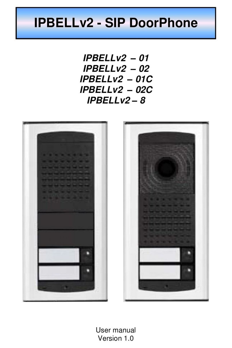
Alpha Technologies IP Bell - 01 Manual

IPBell -SIPdoorentryphonestation
IP Bell – 01
IP Bell – 02
IP Bell – 01C
IP Bell – 02C
Bell – 8 (under development)
Userand installation guide


IPBell -Userguideandinstallationmanual 3
Welcome
Congratulations tothe purchaseofVoIPvideo/audiodoorentry phone station
IPBell. Thisdoorphone can meetyourrequirementsforcommunicationswith
visitorsatthe doorentranceofyourhouse,companyorbuilding.The meaning
ofVoIPis“Voice over InternetProtocol”–thisdoorphone can be connected
tothe computernetwork enabling callsinmode P2P(peertopeer) –that
meansitcallstothe IPaddressofotherVoIPequipmentdirectlyoritcan
registertothe SIPserver,then itcan calltophone numbers.Eachpushbutton
can storetwo25 digitnumbersincluding charactersstar“*”and hash“ # ”.
The basicmoduleofthe doorphone issupplied withone ortwo
pushbuttons, inaudioversion orvideo version withacolourcamera.
The IPBell doorphone can be powered eitherby12Vpowersupplywhich
can be usedforpowering the electricallock ofthedoor,ortheIPBell
doorphone can be poweredbyPoE(PoweroverEthernet).Featuresaresimilar
toahands-free telephone.Among the basicfeaturesyou can find possibilityof
opening twodoorviaelectricallocksand easyconfiguration viaWEB based
interface.
The producerimprovesthe programming toolcontinuosly(firmware).The IP
Belldoorphone canbe upgraded bythe latest version offirmwarewhichyou
can obtainon emailrequest. Forcontact details.
Necessary stepsforthe firmwareupgrade can be found inchapter3.1.10 on
page 34.Wesuggestyoutousethe latestfirmwareversion inorderto
exploit newfeaturesand patches.

IPBell -Userguideandinstallationmanual
4
Contents
1BASIC DESCRIPTION...................................................................................5
1.1 FEATURES ..................................................................................................5
1.2 USEDTERMINOLOGY ..................................................................................6
1.3 MODULESARRANGEMENT...........................................................................8
1.4 FEATURESOFMODULES..............................................................................9
1.4.1 IPBellbasicmodule.............................................................................9
1.4.2 Descriptionofthemainboard..............................................................10
1.5 ASSEMBLYOFTHE IP BELLDOORPHONE ...................................................16
1.5.1 Dismounting ofthefrontcover.............................................................16
1.5.2 IPBellmountingonthewall................................................................16
1.5.3 Replacementofvisitcards....................................................................17
1.5.4 Demountingandmountingofthepushbuttononthefrontpanel............17
1.5.5 ClosingthefrontcoverofIPBell.........................................................18
1.6 INTERCONNECTION OFTWOMODULES (UNDERDEVELOPMENT)..................18
2OPERATIONOFTHEIPBELLDOORPHONE........................................19
2.1 OVERVIEWOFSIGNALLING .......................................................................19
2.2 VISITORATTHEDOORENTRANCE..............................................................19
2.3 PERSONINSIDETHEBUILDING ...................................................................20
2.3.1 Outgoingcall.......................................................................................20
2.3.2 Incommingcall....................................................................................20
3PROGRAMMINGOFPARAMETERS........................................................22
3.1 BASIC VOIP SETTINGS ..............................................................................22
3.1.1 Choice ofmodeandlogin.....................................................................22
3.1.2 Languagesetting.................................................................................24
3.1.3 Networksettings..................................................................................25
3.1.4 PeertopeerorSIPserverconnection..................................................27
3.1.5 Audiocodec setting..............................................................................29
3.1.6 Videosetting........................................................................................30
3.1.7 Viewing thevideo(incl.thePopUpSW)...............................................30
3.1.8 Dayintervals.......................................................................................32
3.1.9 Userinterface......................................................................................33
3.1.10 Servicesetting.................................................................................34
3.1.11 Restart.............................................................................................35
3.1.12 Preparationofstyleand languagemutation.....................................36
3.2 PARAMETERSETTINGSOFTHE IP BELLDOORPHONE ..................................37
3.2.1 Basicparameters.................................................................................37
3.2.2 Sensors ofopendoors..........................................................................38
3.2.3 Allaboutrelays...................................................................................39
3.2.4 Timeparameters..................................................................................41
3.2.5 Directdialling–memorynumbers......................................................42
IPBell -Userguideandinstallationmanual 5
4TECHNICALPARAMETERS......................................................................43
4.1 ELECTRICALPARAMETERS ........................................................................43
4.2 MECHANICALDIMENSIONS........................................................................44
4.3 PARAMETERSOFVIDEO.............................................................................45
1Basicdescription
1.1Features
Øtwo25 digitnumbersstored at eachpushbutton (including *and #)
Øcommandsfordoorhphone can be twoorone digit (command 55can be
shortened toonedigit 5bystoring *5replacingtheoriginal twodigit command55)
Øthe basicmodule(1or2pushbuttons)can be expanded byadd-on 8
pushbutton moduleup tomaximumcapacityof 58 pushbuttons
Øday/night switching –automaticallyormanually
Øprolongation of calldurationbyentering *or#
Øpossibilitytoconnect twoindependent locksfordooropening
Ø5modesofswitches(e.g. camera,illumination, sequentialopening)
Øtwocodesforhang-up of the doorphone viathe telephone
Øtwocodesfordooropening via thetelephone
Øsixaccess codes(passwordsentered viapushbuttonsofthe
doorphone)
Øoptionalnumberofringsbeforeyou answerthe incomming call
Øoptionaltimeperiod betweenindividualpressesofpushbuttonswhen
entering access code viapushbuttonsofthedoorphone
Øoptionaltimeperiod of hang-up during repeating of thedialling
Øoptionaltimeperiod beforestartofthe dialling
Øpowered eitherby12VorPoE(bothnorms)
Øintegrated heating of the circuitboard
Øpernamentillumination ofvisitcards
Øautomaticillumination forcamera(whiteLEDs)
Øintegrated colourcamerawithautofocus
ØEthernet –10/100Mbwithstandard10BaseT and 100BaseTx
ØWebserverforremoteprogramming –BOA
ØLinux2.6operating system
ØUSB connection ofthe internal camera–USB guest 1.1, software
GSPCAsoftwareforvideo transmission toaweb browseron the PC–
W3CAM (J-PEG,RTSPStream)and video streamH.263 / H.264
ØSIPconnection inP2Pmode orSIPProxy(PBXnetwork system)
ØWEB based firmwareupgrades
ØWEB web programmingtool forset-up of doorphone parameters

IPBell -Userguideandinstallationmanual
6
1.2Usedterminology
•Ethernet isafamilyofframe-based computernetworking technologies
forlocal area networks (LANs
•LAN- alocal area network (LAN)isacomputernetwork covering a
smallphysicalarea,likeahome, office,orsmallgroupsofbuildings,
suchasaschool, oran airport.
•10Base-T –10 Mbit/s, ituses8position modularconnectors, usually
calledRJ45 inthe context of Ethernet overtwisted pair.The cables
usuallyused arefour-pairtwisted paircable (though 10BASE-T and
100BASE-TXonlyactuallyrequiretwoof the pairs). Eachofthe
standardssupport bothfull-duplex and half-duplexcommunication.
According tothe standards, theyalloperateoverdistancesofup to
100 meters.
•100Base-TX –socalled FastEthernet,twopairsof UTPorSTP
cable, category 5.
•Twistedpair cabling isatype of wiring inwhichtwoconductors(the
forwardand returnconductorsofasinglecircuit)aretwisted together
forthe purposesofcanceling out electromagneticinterference (EMI)
fromexternalsources;forinstance, electromagneticradiation from
unshielded twisted pair(UTP)cables, and crosstalk between
neighboring pairs.
•UTP,Unshielded Twisted Pair
•STP,Shielded Twisted Pair–the cablingincludesmetalshielding over
eachindividual pairofcopperwires. Thistypeofshielding protects
cablefromexternalEMI(electromagneticinterferences).
•WEB- WorldWide Web(WWW, or web)–aworld-wide application of
HTTPinternet protocol
•HTTP (Hypertext TransferProtocol)isan internetprotocolused
originallyforexchanging hypertext documentsinHTMLformat.
•USB (UniversalSerialBus)–modernwayof connectingexternal
devicestothe computer.
•Video codek („coderand decoder“) -compression H.263 isderived
fromMPEG-4, H.264 isacoderforMPEG-4AVCformat. MPEG-4 isa
type ofvideo compression –decreasing ofdatastreamvideo
sequence
•JPEG isastandardmethod ofloss compression used forsaving digital
images
•Voice over InternetProtocol (VoIP)isatechnologyenabling
transmission ofdigitalized voiceinside the packej ofprotocolsfamily
UDP/TCP/IP viakomputernetwork. I tisused formakingphone calls
via Internet,Intranet oranyotherkind of dataconnection
•TCP/IP containsaset ofprotocolsforcommunication in the computer
network and itisthe mainprotocolof Internet

IPBell -Userguideandinstallationmanual 7
•IPaddress isanumber,whichclearlyidentifiesanetwork interfacein
the computernetwork, whichusesIPprotocol
•DHCP (DynamicHost Configuration Protocol)isan application protocol
fromthe familyof TCP/IP.It isused forautomaticassigning ofIP
addressestoindividual personalcomputersinthe PCnetworks, thus
simplyfing theiradministration
•Internet isaword-wide systemofmutuallyconnected computer
networks
•Intranet isacomputernetwork similartoInternet,butitisaprivate
one. Thatmeansitisjust used forsmallusergroups(e.g. employees
of acompany).
•PoE (PoweroverEthernet)ispowering viadatanetworkcable,withno
need ofbringing the powersupplyviaaseparatecable
•NTP (NetworkTimeProtocol)isaprotocolforsynchronization of
internal computerclock

IPBell -Userguideandinstallationmanual
8
1.3Modules arrangement
The basicmodulesof the IPBelldoorphone aresupplied inthe following
variants–video version IPBell-01C withacameraandone pushbutton,
video version IPBell-02C withacameraand twopushbuttons,audio
version IPBell-01 withone pushbutton,audioversion IPBell-02 withtwo
pushbuttons.Bell-8expansion moduleenablesexpansion byadditional
eightpushbuttons.Thismodulecontains8pushbuttonsand itispossible
toconnectup to7expansion modulesinasequence,thatmeansup to
56 pushbbuttons.Togetherwiththe basicone ortwopushbutton module
you can buildaconfiguration withmaximum57/58 pushbuttons.
IPBell-01 IPBell-02 IPBell-01CIPBell-02C
Bell-8expansion module(underdevelopment)

IPBell -Userguideandinstallationmanual 9
1.4Features ofmodules
1.4.1IPBell basicmodule
IPBellbasicmoduleconsistsofadoorphone boardand aVoIP
moduleboard,connectorsconnection and set-up elementsareshownon
picture1(fig.1).
IPBellshouldbe powered eitherbyPoEtechnologyormin.11VAC-
max.15VACormin.12VDC -max.18VDC whichyouconnecttothe "12V"
clamp.IPBellpowerconsumption ismax.300mA.Thispowersupplycan be
alsoused forpowering electricallock(s),then you need toadd the power
consumptionsoflock(s).Usuallyyou can useapowersupply12VAC/1A÷2A
or12VDC/1A÷2A.
IPBellisequipped byacircuitforpowering viaUTPcable–PoE.Ifyou
haveaPoEswitchoryou haveaPoEadapter,then you do notneed touse
12Vpowersupplyforpowering the doorphone.Ifyouusean electricallock,
you need tousean externalpowersupply(onlyforcircuitwithrelaycontacts),
oryou need tousealow-consumption lock and then powerthislock bya
yellowcablewithwhiteconnector,whichyou inserton 2pinsofaconnector
situated between clampsforconnection of1st and 2nd switch.When using PoE,
hereis12V/350mA available.(fig. 5)
Fig. 1Trimmers onthemainboard

IPBell -Userguideandinstallationmanual
10
1.4.2Description ofthemainboard
1. trimmerforsetting levelofsurrounding illumination (sensor–10). During
the call,atthe setlevel, cameraillumination willbe switched on (white
LEDs-9)–applies tocameramodelsonly
2. echo cancellation trimmer.The IPBelldoorphone isahands-free
telephone. Anysound comming tothe speakerisreceived bythe
microphone and sent back withadelay(echo).Tocompensatethis,the IP
Bellusesacircuitforreducing the amplification pathofthe microphone
depending on the levelofincomming signal.Thislevelcan be set bythe
Echo cancellation trimmer(2).
3. trimmerforsetting sensitivityofthe microphone
4. trimmerforsetting volumeof the speaker
5. connectorforconnection of the speaker(glued on inthefront caseofthe
housing)
6. PoEpowersupplymodule
7. camera(Microsoft LifeCamVX700) –appliesto cameramodelsonly
8. signalLEDof the IPBelldoorphone status –appliesto cameramodelsonly
9. LEDforcameraillumination when surrunding lightisinsufficient -4xwhite
LED, activeduring acallonly,theycanbe switched off bySWsetting –
appliesto cameramodelsonly
10. sensorofsurrounding lightlevel –appliestocameramodelsonly
11. VoIPmodule-green LED–powersupplyof VoIPmodule
12. VoIPmodule–green LED–LANconnection,yellowLED–
datatransmission overLAN
13. DIPswitch–selection ofmode and basicsettings
14. connectorforconnection the expansion moduleBell-8
15. terminalof the 2nd switch(switching contact)
16. terminalof the 1st switch(switching contact)
17. connection of 12V.When PoEisnot used, then thisisthe input of12V
AC/DC
18. connectorsforpowering the low-consumption electricallockwhen PoE
powersupplyisused. Foreasyinstallation you can useyellowcablewith
connector(fig. 5). Thisis12VDC outputonly!Donotconnectto the
power supply!
19. connection toLAN,itisconnected byUTPcableCAT5.Thisconnection is
compatiblewith10/100/1G network and PoEaccordingtonorm
IEEE802.3afmode Aand mode B.Dataconnection 10Base-T and
100Base-TXsupported
20. connection of pushbuttonstothe mainboard
21. microphone
22. connection ofvisit cardsillumination tothe main
board

IPBell -Userguideandinstallationmanual11
Fig. 2ThemainboardoftheIPBell doorphone

IPBell -Userguideandinstallationmanual
12
Fig. 3Connectionofthepushbuttonsand visitcardsillumination
Connection ofswitching contactsterminalisshownon fig.2.Label
"NO"meansnormallyopen contact, "COM"meanscommon outlet (middle)and
"NC"meansnormallyclosed contact. Contactsofbothswitchesareisolated
galvanicallyfromeachotherand alsofromothercircuitsofthe IPBell
doorphone. Variantsof switchesconnection areshownon fig. 4and 5.

IPBell -Userguideandinstallationmanual13
Fig. 4Examples ofswitching contactsconnection withoutPoEpower
supply

IPBell -Userguideandinstallationmanual
14
Fig. 5Exampleofswitching contactsconnectionwhenusingPoEpower
supply
Attention–theelectricallock islow-consumption, max. 350mA
Camera (Microsoft LifeCamVX700)is
mounted on astandalone modulewhich
you can find incameraversionsonly.
The cameraviewanglecan´tbe
changed inanyway.Thereforewe
suggesttofollowthe installation height
of the IPBellasshownon the figure.

IPBell -Userguideandinstallationmanual15
Voice communication set-up –the default trimmerpositonsarefactory set as
shownonthe fig.2.Change ofsettingscan be done asneeded.The meaning
ofturning worksinastandardway,thatmeansbyturning tothe rightthe set
value increases. Asthe IPBelldoorphone isahands-free telephone, during the
call the signalfromthe speakerisreturning tothe microphone andthe calling
partyreceivesitwithadelay(itiscaused bydigitalprocessing and signal
transmission).ThereforeIPBellisequipped withacircuitforechocancellation
and you need topaymoreattention during settingsofthistrimmer.The
required levelmeansatwhatlevelofsound the microphone inthe IPBell
doorphone isturning off toavoidreturning the sound withadelay.
Trimmerforsetting the sensitivitylevelofsurroundingillumination.During the
call,atthe setsensitivitylevel,cameraillumination will be switched on (white
LEDs). It isactiveduring activecallonly.Ifthe LEDillumination isturned on
then itwillbe switched off onlyafterthe callisfinished.ThatpreventsLED
flickering during the call.
DIPswitch setting ofdefaultvaluesand IPBell modewith
the DIPswitch–fig. 6.
1-reserve
2-switching toP2P/ SIPservermode
3-factory settings–deletesall valuestothe factory settings
except forthe momoryof numbers
4-setsthe detault IPaddress to192.168.1.250
Allchangesalwaysappearafterturning off and turningon
the powersupply(restart).
Afterthe VoIPmodulehasbeen activated, the DIPswitch3
and 4mustbe switched back to"on"
position.Otherwisethe newlyset
parametersand the newIPaddresswill
be set back tothedetault valuesafterthe restart.
Fig.
6
DIPswitch setting

IPBell -Userguideandinstallationmanual
16
1.5AssemblyoftheIPBell doorphone
1.5.1Dismounting ofthefront
cover
1.5.2IPBell mounting on thewall
Mounting is
done withwall
plugsand
screws.
Wesuggest
wall plugswith
5mm in
diameter,the
screwwith
half-round
head,
diameter
4mm, length
35mm

IPBell -Userguideandinstallationmanual17
1.5.3Replacementofvisitcards
Eachpushbutton hasgotitsownlabelheldwiththe whiteplasticcup (see the
figureabove).Demounting and inserting ofthe capcan be donewithtwo
fingersalong the longerside of the cap byasoft pull/push.
1.5.4Demounting and mounting ofthepushbutton on the
frontpanel

IPBell -Userguideandinstallationmanual
18
1.5.5Closing thefrontcoverofIPBell
1.6Interconnectionoftwomodules (underdevelopment)

IPBell -Userguideandinstallationmanual19
2OperationoftheIPBell doorphone
2.1Overview ofsignalling
The IPBelldoorphone signalsacusticallystatuses,whichcan occur
during operation,anothersignalling isprovided withred LED(located nextto
the camera–validforcameraversionsonly).
Status Tones Tonefrequency
LED
Linepickup – –■–▀– 425-850-1275 shines
Linehangup –▀–■–1275-850-425 goes
out
Report aftercalling– –■–▀– 425-850-1275 shines
Commandconfirmationfrom
phone(parameterconfirmation) ––█–– 425
Notificationaboutcallend –■–■–■– 1275 shines
Lineconnection(Reset) –■––■– 1275-850-1275 blinks
Error(generallyanything
unsuitable) –■–■–■–■–■–■– 425….
Emptymemory(nonumber
programmed) –█––■––■–– 850-1275-1700…
Establishing connection - blinks
Connectionestablished–active
call- shines
2.2Visitoratthedoorentrance
IPBellfunctionalityisinfluenced bysettingsofdoorphone parameters.
Pushbuttons ofthe doorphone areprovided withnametags.The visitor
pressesadesired pushbutton,the doorphone picksup the line either
immediately(the pushbutton isnotthe firstdigitoftheaccesscode)orwitha
delay(timeperiod between induvidualpressesofthe pushbuttons)and dialsa
preprogrammed telephone number.The dialled numberdiffersonlyaccording
tothe set dialling mode of the doorphone:
- Day/Night mode =ifthe doorphone issettothe Daymode,italways
dialsnumbersetinthe firstcolumn.Ifthe doorphone issettothe Night
mode,italwaysdialsnumbersetinthesecondcolumn.Day/Night
mode switcihng can be done manuallyorautomatically.See the basic
parameterssettings.Ifyou chooseDay/Nightswitching,then “Daily
intervals”appearinthe web interfacemenu.Hereyou can setup to3
dailyintervalsfor7daysperweek.Correctfunctionalityrequiressetting
IPaddress ofNTPserverand network setting enablinginternetaccess

IPBell -Userguideandinstallationmanual
20
forthe IPBelldoorphone.Inthe automaticDay/Nigh switching you can
makeuseoftemporarymanualswitching,whichiscancelled bygoing
through the first nearest automaticswitching interval.
-mode 2groups of numbers=firstpressing–alwaysdialsthe number
setinthe 1st column,byrepeated pressing ofthe samepushbutton or
whenbusytone isdetected,orafterelapsing the setnumberofrings
“timeperiod beforethe call afterselection for'repeatdialling'”, the
doorphone dialsthe 2
nd numberofthe second group (2
nd column).
When you press the samepushbutton onceagain,itwilldialthe
numberofthe 1st group,etc.(ifbusytone isdetected afterdialing the
numberof the 2nd group, the repeated dialling isfinished).
Ifthe visitorpressesapushbutton afterthe doorphone picked up the line,
the doorphone firsthangsup forasettimeperiod “Timeofhang up before
repeated dialling”and then itpicksup the line and dialsanewnumber.
The switching contactcan be controled withpushbuttonsofthe
doorphone (codelock).If the visitorat the doorentrancepressespushbuttons
inacombination matching the pre-setcode and thetimeperiod between
individual pressesinnotlongeerthan the settimeperiod,then the doorphone
switchesthe relevantswitching contact(ifitissetinmode m=1orm=5)fora
timeperiod defined by “Timeperiod of switching”.
2.3Personinsidethebuilding
The person inside the building isthe person whichisintelephone
connection withthe IPBelldoorphone.
2.3.1Outgoing call
The outgoing callisthe call ofthe doorphone (initiated bythe visitor).
Afterthe doorphone hasdialled anumber,atelephone inside the building is
ringing.When the callisanswered,you cantalktothe visitoratthe door
entrance.Bydialling acode you can switchon aswitching contact, if itissetto
mode m=1orm=5,you can changethe Day/Nightmode andhangup.10 sec.
beforethe end ofthe callthe doorphone sendsan alerttone aboutthe call
ending.By dialling acharacterstarorhash(*/#)you can extend the call.By
hanging up the telephone the call isfinished.
Therearetwopossiblewaysoftransmitting informationonpressed
pushbutton(acommand foropening thelock,day/nightswitching,
extending thecall,acommand forcall hang up)–eitherin“RTPchannel”
orin“SIPinfo”.“inband DTMF”optionisnotdecodedintheIPBell doorphone.
2.3.2Incomming call
The incomming call isacalltothe doorphone (initiated bythe person inside the
building).Afterdialling an extension numberorIPaddress,towhichthe IPBell
This manual suits for next models
7
Table of contents
Other Alpha Technologies Intercom System manuals

Alpha Technologies
Alpha Technologies GSM-VarioBell User manual

Alpha Technologies
Alpha Technologies Brave Slim - C User manual

Alpha Technologies
Alpha Technologies PDP - 00 User manual

Alpha Technologies
Alpha Technologies IP bell User manual

Alpha Technologies
Alpha Technologies IPBELLv2-01 User manual

Alpha Technologies
Alpha Technologies GDI Bell Owner's manual