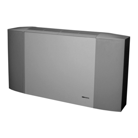
alphainnoTec LWC 60 + VenTower 300 User manual

We reserve the right to modify technical specifications without prior notice.
83030600bUK– Translation of the original instruction manual © ait-deutschland GmbH
Operating Manual
VENTOWER
UK

2We reserve the right to modify technical specifications without prior notice.
83030600bUK © ait-deutschland GmbH
Please read rst
This operating manual provides important information
on the handling of the unit. It is an integral part of the
product and must be stored so that it is accessible in the
immediate vicinity of the unit. It must remain available
throughout the entire service life of the unit. It must be
handed over to subsequent owners or operators of the
unit.
Read the operating manual before working on or
operating the unit. This applies in particular to the
chapter on safety. Always follow all instructions
completely and without restrictions.
It is possible that this operating manual may contain
instructions that seem incomprehensible or unclear. In
the event of any questions or if any details are unclear,
contact the factory customer service department or the
manufacturer’s local partner.
Since this operating manual was written for several
different models of the unit, always comply with the
parameters for the respective model.
This operating manual is intended only for persons
assigned to work on or operate the unit. Treat all
constituent parts condentially. The information
contained herein is protected by copyright. No part of
this manual be reproduced, transmitted, copied, stored
in electronic data systems or translated into another
language, either wholly or in part, without the express
written permission of the manufacturer.
Symbols
The following symbols are used in the operating manual.
They have the following meaning:
Information for operators.
Information or instructions for qualied techni-
cians.
DANGER!
Indicates a direct impending danger
resulting in serious injuries or death.
WARNING!
Indicates a potentially dangerous situation
that could result in severe injuries or
death.
CAUTION!
Indicates a potentially dangerous situation
that could result in medium or slight
injuries.
ATTENTI ON.
Indicates a possibly dangerous situation, which
could result in property damage.
NOTICE.
Emphasised information.
€ENERGY SAVING TIP
Indicates suggestions that help to save energy,
raw materials and costs.
Reference to other sections of the operating
manual.
Reference to other documents of the manufac-
turer.

3
Contents
INFORMATION FOR OPERATORS AND
QUALIFIED SPECIALISTS
PLEASE READ FIRST..................................................................2
SYMBOLS .....................................................................................2
INTENDED USE..........................................................................4
DISCLAIMER................................................................................4
EC CONFORMITY .....................................................................4
SAFETY.........................................................................................4
CUSTOMER SERVICE ................................................................5
WARRANTY / GUARANTEE...................................................5
DISPOSAL ....................................................................................5
HOW THE VENTILATION MODULEWORKS....................6
AREA OF UTILISATION............................................................6
OP ER ATIO N................................................................................6
MAINTENANCE OF THE UNIT...............................................6
Filters......................................................................................6
Counterflow plate heat exchanger ....................................7
Fans .........................................................................................8
Condensate discharge ..........................................................8
Hot-water tank......................................................................9
SUMMER FUNCTION................................................................9
MALFUNCTIONS.....................................................................10
INSTRUCTIONS FOR QUALIFIED TECHNICIANS
SCOPE OF DELIVERY .............................................................. 11
Scope of KHZ air/water unit............................................. 11
Available unit variants ........................................................12
Possible unit variants..........................................................12
Accessories necessary for operation ..............................12
Additional accessories .......................................................13
INSTALL ATION ........................................................................13
Installation location............................................................13
Transport to installation location....................................13
Installation............................................................................15
DOMESTIC HOT WATER TANK INTEGRATION.............16
Integration in a KHZ-LW...................................................17
Integration VenTower with Brine/water Compact,
Water/water Compact, Ait/Water outdoor
installation (dual) ..........................................................17
INSTALLATION OF THE VENTILATIONDUCT...............18
Outdoor, supply air and exhaust air integration ...........18
Extract air integration (KHZ-LW only …) .....................18
ELECTRICAL CONNECTIONS .............................................19
CONTROL UNIT OF THE VENTILATIONAND
DOMESTIC HOT WATER MODULE..............................21
FLUSHING, FILLING AND BLEEDINGTHE SYSTEM.......22
Flushing, filling and bleeding the domestic hot water
tank .................................................................................22
INSULATING THE HYDRAULICCONNECTIONS ..........22
CONDENSATE DISCHARGE .................................................22
COMMISSIONING ...................................................................23
DISMANTLING .........................................................................23
TECHNICAL DATA / SCOPE OF DELIVERY ........................24
PERFORMANCE CURVES
Available external compression
VenTower_300.....................................................................26
VenTower_4 0 0 .....................................................................27
Fan characteristic curves
VenTower_300.....................................................................28
VenTower_4 0 0 .....................................................................29
VENTOWER ..............................................................................30
Dimensional drawings ........................................................30
Installation plan...................................................................31
KHZ AIR/WATER .....................................................................32
Dimensional drawings ........................................................32
Installation plan version 1 .................................................33
Installation plan version 2 .................................................34
Installation plan version 3 .................................................35
Installation plan version 4 .................................................36
Installation plan version 5 .................................................37
Installation plan version 6 .................................................38
TERMINAL DIAGRAM............................................................ 40
CIRCUIT DIAGRAM.................................................................41
APPENDIX
EC DECLARATION OF CONFORMITY..............................42
We reserve the right to modify technical specifications without prior notice.
83030600bUK – Translation of the original instruction manual © ait-deutschland GmbH

4We reserve the right to modify technical specifications without prior notice.
83030600bUK © ait-deutschland GmbH
Intended use
The unit is solely to be used for its intended use together
with the heat pump supplied with it. This means:
•for controlled apartment ventilation with heat
recovery,
•for domestic water heating.
The unit may be operated only within its technical
parameters.
“Technical data / Scope of delivery” overview,
page 24
The following are not permitted:
•use of greasy exhaust air, explosive gases, air
containing dust, adhesive aerosols;
•the connection of range hoods to the ventilation
system,
•the heating of any media other than domestic hot
water.
ATTENTI ON
Before using the unit, precise ventilation plan-
ning by a qualied person is necessary.
Disclaimer
The manufacturer is not liable for losses resulting from
any use of the unit which is not its intended use.
The manufacturer’s liability also expires:
•if work is carried out on the unit and its
components contrary to the instructions in this
operating manual.
•if work is improperly carried out on the unit and
its components.
•if work is carried out on the unit which is not
described in this operating manual, and this
work has not been explicitly approved by the
manufacturer in writing.
•if the unit or components in the unit have been
altered, modied or removed without the explicit
written consent of the manufacturer.
EC conformity
The unit bears the CE mark of conformity.
EC declarations of conformity, page 42
Safety
The unit is safe to operate for its intended use. The
construction and design of the unit conform to the
current state of the art standards, all relevant DIN/VDE
regulations and all relevant safety regulations.
Every person who performs work on the unit must
have read and understood the operating manual prior
to starting any work. This also applies if the respective
person has already worked with such a unit or a similar
unit or has been trained by the manufacturer.
Every person who performs work on the unit must
comply with the applicable accident prevention and
safety regulations. This applies in particular to the
wearing of personal safety gear.
DANGER!
Unit operates under high electric voltage!
DANGER!
Danger of fatal injury due to electric
current!
Electrical connections may be installed
only by qualied electricians.
Before opening the unit, disconnect the
system from the power supply and secure
it from being switched back on!
DANGER!
Qualied trained personnel only (qualied
heating, cooling system, refrigeration
or refrigerant technician or electrician)
may carry out work on the unit and its
components.
WARNING!
Observe safety labels on and in the unit.
ATTENTI ON
For safety reasons:
Never disconnect the unit from the power sup-
ply, unless the unit is being opened.

5
We reserve the right to modify technical specifications without prior notice.
83030600bUK – Translation of the original instruction manual © ait-deutschland GmbH
CAUTION!
Only switch on the unit if exhaust air,
supply air and outdoor air pipes have been
connected to the unit.
ATTENTI ON
Only switch on and operate the unit if exhaust
and outside air lters have been installed and the
domestic hot water tank is full.
DANGER!
If there are open replaces in the apart-
ment (tiled stoves, hearths, etc.), ensure
that when these replaces are in use the
combustion air ow is routed separate-
ly from the ventilation system (ask the re-
sponsible chimney sweep, as the regulati-
ons differ from region to region).
See note under under “Accessories” section,
page 12
NOTICE.
As air is blown in only in living rooms and bed-
rooms and air is extracted only from rooms with
odours and moisture, install ventilation grilles in
the connecting doors or walls or enlarge the air
gap under doors accordingly to ensure unhin-
dered airow.
Customer service
For technical information please contact a qualied
technician or the manufacturer’s local partner.
Operating instructions for your heat pump,
Appendix, customer service, addresses for service
Warranty / Guarantee
For warranty and guarantee conditions, please refer to
the purchase documents.
NOTICE.
Please contact your dealer concerning warran-
ties and guarantees.
Disposal
If taking the old unit out of service, comply with the
relevant local laws, guidelines, directives and standards
on the recovery, reuse, recycling and disposal of
resources and components of cooling units.
“Dismantling”, page 23

6We reserve the right to modify technical specifications without prior notice.
83030600bUK © ait-deutschland GmbH
How the ventilation
moduleworks
The heat recovery takes place via a highly efcient
counterow plate heat exchanger. Energy is removed
from the exhaust air. This is mainly dissipated in the
outdoor air in the plate heat exchanger and reaches
living rooms and bedrooms with the supply air.
The outdoor air must always be heated to temperatures
> – 5 °C before entering the ventilation module. The
air is either heated by a so-called geothermal heat
exchanger or by an electric heating coil.
Accessories necessary for function, page 12
Both the exhaust air and the outdoor air are fed though
a macro fold lter where it is ltered.
The two fans are each arranged as induced draught fans
across the air/air counterow plate heat exchanger.
Area of utilisation
Taking into account the ambient conditions, use limits
and the relevant regulations, each VenTower (VTS), each
“Comfort” central building services control (KHZ) can
be used in new or existing heating systems.
“Technical data / scope of delivery” overview,
page 24
Operation
By opting to install a heat pump or ventilation system
you will be making a contribution for many years to come
to spare the environment through low emissions and less
use of primary energy.
You can operate and control the heat pump system
with the control element of the heating and heat pump
regulator.
NOTICE.
Ensure correct controller settings.
Operating manual of the heating and heat pump
regulator.
Maintenance of the unit
ATTENTI ON
Keep the air inlet and air outlet openings in the
external wall free of leaves and snow.
FILTERS
Regularly inspect the outside air and the exhaust air lter
for dirt (monthly or more often if necessary, depending
on dirt and dust in the outside air).
A default interval of four months is set in the heating
and heat pump controller, until a lter replacement is
prompted.
ATTENTI ON
Use only original accessories from the manufac-
turer of the unit.
Proceed as follows:
Switch off the unit and then open the upward
swivelling / hinged door of the ventilation and
domestic hot water module…
•
To do this, undo the quick-release screws of the
swivelling door of the ventilation and domestic hot
water module. Turn through 90° to the left…
•
Fold the swivelling door of the ventilation and
domestic hot water module upwards…

7
We reserve the right to modify technical specifications without prior notice.
83030600bUK – Translation of the original instruction manual © ait-deutschland GmbH
Pull out the two lters on the top right and left-
hand side of the heat exchanger, one after the other,
from the front, check each for dirt and if necessary
replace…
Push the lters into the positions provided in the
unit, fold down the swivelling door of the ventilation
and domestic hot water module, tighten the quick-
release screws and switch unit back on again.
ATTENTI ON
Ensure the lters are installed in the correct po-
sition. To this end, follow the instructions on the
lter cassette.
The actual lter has a pre-lter upstream of it, as more
dirt is trapped by the lter during and immediately after
the construction phase. 8 weeks after moving in and
starting up the ventilation for the rst time, remove
these pre-lters and dispose of in an environmentally
friendly way.
COUNTERFLOW PLATE HEAT EXCHANGER
Clean the counterow plate heat exchanger once a year.
Proceed as follows:
Switch off the unit and then open the upward
swivelling / hinged door of the ventilation and
domestic hot water module…
Maintenance of the unit, lter, , page 6
Pull out the two lters on the top right and left-
hand side of the heat exchanger, one after the other,
from the front…
Then pull the moulded part above the heat
exchanger out of the unit from the front…

8We reserve the right to modify technical specifications without prior notice.
83030600bUK © ait-deutschland GmbH
Then lift the heat exchanger up slightly and carefully
pull it out of the unit from the front…
ATTENTI ON
Do not bend or damage the plates of the heat
exchanger when pulling it out or during the sub-
sequent cleaning.
Straighten any plates accidentally bent before
pushing the cleaned heat exchanger back into
the unit.
Clean heat exchanger with hot water and
proprietary washing up liquid and leave to dry in the
air outside the unit…
ATTENTI ON
Do not use solvents or acidic cleaning agents.
NOTICE.
We recommend using a shower head to clean
the heat exchanger.
After cleaning and drying the heat exchanger, push
it back into the unit. Then push the moulded part
and lters into the unit…
ATTENTI ON
Ensure the lters are installed in the correct po-
sition. To this end, follow the instructions on the
lter cassette.
Fold down the swivelling door of the ventilation
and domestic hot water module, tighten the quick-
release screws and switch unit back on again.
FANS
Once a year, have the fans checked by qualied personnel
and if necessary have them cleaned.
If the air-handling capacity of the unit no longer seems
to be sufcient, check the two lters at the top right and
left-hand side of the heat exchanger for dirt rst and if
necessary replace.
NOTICE.
If a geothermal heat exchanger and/or a de-
froster heating is used in conjunction with the
ventilation module, check the lters of the rele-
vant units for dirt too and if necessary replace.
If changing the lter(s) does not result in any
improvement in the unit’s air-handling capacity, check
all the air inlets and outlets for blockages or damage
(cracks). If necessary, remove all obstructions in the air
volume ow.
In addition, check whether the supply air and exhaust
valves are free of obstructions and that their original
settings are unchanged.
CONDENSATE DISCHARGE
ATTENTI ON
Regularly check to ensure that the condensate
can drain out of the unit unobstructed. To do
this, regularly check the condensate tray in the
unit and the condensate discharge for dirt /
blockages and if necessary clean.

9
We reserve the right to modify technical specifications without prior notice.
83030600bUK – Translation of the original instruction manual © ait-deutschland GmbH
HOT-WATER TANK
The domestic hot water tank of the ventilation and
domestic hot water module should be cleaned once a
year by qualied personnel. To do this, rst drain the
domestic hot water tank of the ventilation and domestic
hot water module.
Switch off the unit and then open the upward
swivelling / hinged door of the ventilation and
domestic hot water module…
Maintenance of the unit, lter, , page 6
Unscrew the front facing panel of the ventilation
and domestic hot water module…
Drain the domestic hot water tank through the valve
mounted on site at the cold water connection…
After completely draining the tank, remove the
foam cover above the service opening of the
domestic hot water tank, unscrew the ange cover
of the service opening and clean the domestic hot
water tank…
1 Electrical switch cabinet, ventilation
and domestic hot water module
2 Service opening, domestic hot water tank
(shown here without foam cover)
3 External current anode (under foam cover)
Then tightly close the ange cover again, insert the
foam cover and replace the front panel back on the
ventilation and domestic hot water module…
Fold down the swivelling door of the ventilation
and domestic hot water module, tighten the quick-
release screws and switch unit back on again...
Rell the domestic hot water tank of the ventilation
and domestic hot water module.
Check the safety valve (provided by customer) for the
hot water tank at regular intervals. Since an external
current anode is built in, the anode requires no
maintenance.
It is a good idea to have a maintenance contract with a
heating installation company. The company will conduct
all required maintenance at regular intervals.
Summer function
NOTICE.
The summer function can only be used in con-
junction with a geothermal heat exchanger (pro-
vided by the customer).
To prevent the supply air from being blown into the
rooms preheated during the hot season, you must
uncouple the heat exchanger from the air ow.
Switch off the unit and then open the upward
swivelling / hinged door of the ventilation and
domestic hot water module and remove the two
lters from the unit…
Maintenance of the unit, lter, , page 6
Pull out the two lters on the top right and left-
hand side of the heat exchanger and pull out the
moulded part above the heat exchanger from the
front of the unit…
Maintenance of the unit, counter ow heat
exchanger, – , page 7
Remove the small triangular piece from the moulded
part…
1 “Large” triangular piece
2 “Small” triangular piece

10 We reserve the right to modify technical specifications without prior notice.
83030600bUK © ait-deutschland GmbH
NOTICE.
Store the “small” triangular piece in a safe dry
place until the end of use of the summer func-
tion.
Push the “large” triangular piece only back into the
unit…
Then push the left and right-hand lters back into
the unit…
ATTENTI ON
Ensure the lters are installed in the correct po-
sition.
Push the partition (red plastic panel) supplied with
the ventilation and domestic hot water module into
the unit, under the right-hand lter (= outside air
lter)…
The partition prevents the outside air from owing
through the heat exchanger during use of the
summer function…
Fold down the swivelling door of the ventilation
and domestic hot water module, tighten the quick-
release screws and switch unit back on again.
NOTICE.
Depending on your subjective feelings, you can
cancel the summer function at any time during
the transition period in the spring or autumn
by removing the partition from the unit and t-
ting the “small” triangular piece back into the
moulded part.
We recommend not activating the actual heating
mode via the heat pump until the supply air can
no longer acquire the required heat through op-
eration of the ventilation module alone.
NOTICE.
After removing the partition, store it always to
hand near the unit.
Malfunctions
In case of malfunctions, you can read out the cause of
the fault from the diagnostics program of the heating and
heat pump controller.
Operating manual for the heating and heat pump
regulator.
DANGER!
Only customer service personnel
authorised by the manufacturer may carry
out service and repair work on the unit’s
components.
Operating instructions for your heat pump,
Appendix, customer service, addresses for service

11
We reserve the right to modify technical specifications without prior notice.
83030600bUK – Translation of the original instruction manual © ait-deutschland GmbH
NOTICE.
The corresponding “Compact” air/water or
brine/water heat pump is delivered on a sepa-
rate pallet as a further part of the scope of de-
livery for the “Comfort central building services
control (KHZ)”. The ventilation and domestic
hot water module and the “Compact” air/water
or “Compact” brine/water heat pump delivered
on a separate pallet together form the central
building services control (KHZ).
SCOPE OF KHZ AIR/WATER UNIT
1 VenTower VTL ventilation and
domestic hot water module
plus 2 “Compact” air/water heat pump
= 3 KHZ air/water
Scope of delivery
Exemplary arrangement of the “Ventilation and domestic
hot water module” scope of delivery:
VenTower ventilation and domestic
hot water module with
• integrated domestic hot water
tank (enamelled to DIN4753,
insulated on the outside and
including external current anode)
VTL … for KHZ-LW only:
• Connection set for hydraulic
integration of the domestic hot
water tank (in the extra box)
• Connecting sleeve and
intake cover for extract air
integration (in the extra box)
VTS …:
• Switching valve and ventilation
circuit board 2.0 (in the extra box)
Complete the following rst:
Inspect delivery for outwardly visible signs of
damage.
Check scope of delivery for completeness…
Any defects or incorrect deliveries
must be claimed immediately.

12 We reserve the right to modify technical specifications without prior notice.
83030600bUK © ait-deutschland GmbH
AVAILABLE UNIT VARIANTS
KHZ AIR/WATER:
LWC 60 + VenTower_300 = KHZ-LW 60/300
LWC 60 + VenTower_400 = KHZ-LW 60/400
LWC 80 + VenTower_400 = KHZ-LW 80/400
POSSIBLE UNIT VARIANTS
AIR/WATER DUAL OUTDOOR INSTALLATION:
LWD 50A + VenTower_300
LWD 50A + VenTower_400
LWD 70A + VenTower_300
LWD 70A + VenTower_400
AIR/WATER OUTDOOR INSTALLATION:
LW 71A + VenTower_300
LW 71A + VenTower_400
LW 81A + VenTower_300
LW 81A + VenTower_400
BRINE/WATER COMPACT:
SWC 60H + VenTower_300
SWC 60H + VenTower_400
SWC 70H + VenTower_300
SWC 70H + VenTower_400
SWC 80H + VenTower_300
SWC 80H + VenTower_400
SWC 100H + VenTower_300
SWC 100H + VenTower_400
BRINE/WATER COMPACT WITH PASSIVE COOLING:
SWC 60H/K + VenTower_300
SWC 60H/K + VenTower_400
SWC 70H/K + VenTower_300
SWC 70H/K + VenTower_400
SWC 80H/K + VenTower_300
SWC 80H/K + VenTower_400
SWC 100H/K + VenTower_300
SWC 100H/K + VenTower_400
WATER/WATER COMPACT:
WWC 100H/X + VenTower_300
WWC 100H/X + VenTower_400
ACCESSORIES NECESSARY FOR OPERATION
ATTENTI ON
Use only original accessories from the manufac-
turer of the unit.
Air duct system 700 (accessory which must be
purchased; required for KHZ-LW … only)
The individual components of the air duct system
700 (with air duct accessories) must be ordered as an
additional item depending on the planned installation of
the central building services control for air/water.
“KHZ air/water installation plans”, from page
36
Defroster heating (DH) (accessories for additional
cost)
for preheating the outdoor air. Consisting of 2.0 kW
heating coil for installation in the air duct, duct sensor,
thermostat, controller and an air lter box.
The defroster heating is absolutely necessary for systems
without geothermal heat exchanger!
NOTICE
If a replace (stove) is to be set up, the local ma-
ster chimney sweep (qualied chimney sweep,
stove inspector or equivalent person) must be
consulted in advance on whether and what sa-
fety devices are required for simultaneous ope-
ration of the air-conditioning system and a re-
place!

13
We reserve the right to modify technical specifications without prior notice.
83030600bUK – Translation of the original instruction manual © ait-deutschland GmbH
ADDITIONAL ACCESSORIES
ATTENTI ON
Use only original accessories from the manufac-
turer of the unit.
Pollen lter (lter class F5)
(accessories for additional cost)
for the outside air intake area as a substitute for the
standard lter.
Standard lter (lter class G4)
(accessories for additional cost)
as replacement for the lter(s), replaced as standard
lters in case of servicing.
Replacement lter (accessories for additional cost)
for the air inlet cover.
Replacement lter (accessories for additional cost)
for the defroster heating.
Room remote adjuster (accessories for additional
cost)
for increasing or lowering the set temperature by up to
5K and with forced ventilation function.
Installation
Observe the following when performing all work:
NOTICE.
Always comply with applicable accident pre-
vention regulations, statutory regulations, ordi-
nances and directives.
WARNING!
Qualied personnel only may install and
assemble the heat pump or heat pump
system!
NOTICE.
Observe the sound levels of the respective
model.
“Technical data / Scope of delivery” overview,
“Sound” section, page 24
INSTALLATION LOCATION
CAUTION.
Only install the unit indoors.
The installation area must be frost-free and dry. It must
full the requirements of EN 378. It must also full the
regulations which apply locally.
Dimensional drawing and installation plan for the
respective unit type, from page 34
TRANSPORT TO INSTALLATION LOCATION
Always comply with the following safety information
during transport:
DANGER!
Several people are required to transport
the unit. Do not underestimate the weight
of the unit.
“Technical data / Scope of delivery” overview,
“General unit data” section, page 24

14 We reserve the right to modify technical specifications without prior notice.
83030600bUK © ait-deutschland GmbH
ATTENTI ON
Lift the unit from the bottom of the unit only.
Never exert lifting or transport pressure on the
top part of the unit (area with fold open door).
DANGER!
The unit can tip when being removed from
the wooden pallet and during transport.
This can result in personal injury and
damage to the unit.
– Take suitable precautions to prevent
the risk of tipping over.
DANGER!
Make sure to secure unit against slipping
during transport.
ATTENTI ON
Never use components and connections on the
unit for transport purposes.
ATTENTI ON
Do not damage connections on the unit under
any circumstances.
To prevent transport damage, you should transport the
unit to its nal place of installation in its packed condition
(on the wooden pallet with packaging) using a pallet
truck.
If transport to the nal installation location using a
pallet truck is not possible, you can also transport the
ventilation and domestic hot water module on a hand
truck.
TRANSPORT WITH A HAND TRUCK
Proceed as follows:
Remove packaging and set extra box aside (will be
needed later on!)...
Dispose of the transport and packaging materials
properly and under ecological aspects…
Lift unit from pallet.
ATTENTI ON
Lift the unit from the bottom of the unit only.
Never exert lifting or transport pressure on the
top part of the unit (area with fold open door).
Push the hand truck under the unit at the rear of
the unit and transport the unit to the installation
location.
ATTENTI ON
Transport with a hand truck on the front side of
the unit is not permitted.
ATTENTI ON
Do not damage the hydraulic connections under
any circumstances.
ATTENTI ON
Use a special hand cart for stairs if the transport
route passes along stairs and slowly lower the
unit step by step.
TRANSPORT OVER STAIRS WITHOUT HAND CART
Secure the unit with ropes or similar and slowly slide it
down two wooden planks.
ATTENTI ON
Use the base frame part of the rear of the unit
only as a sliding edge.

15
We reserve the right to modify technical specifications without prior notice.
83030600bUK – Translation of the original instruction manual © ait-deutschland GmbH
INSTALLATION
DANGER!
Several people are required to install the
unit.
NOTICE.
Always observe the installation plan for the re-
spective model. Note the size and minimum
clearances.
For installation plans of the respective unit type,
from page 35 (KHZ air/water or VenTower)
Install the unit so that the swivelling door at the front
is accessible at all times and can be completely opened.
Proceed as follows:
Install the corresponding heat pump according
to the requirements of the relevant operating
manual…
“Installation” section in the operating manual of
the respective heat pump
If you have not yet done so, remove the packaging
from the ventilation and domestic hot water
module, place the extra box to the side (is required
later!) and lift the ventilation and domestic hot
water module off the wooden pallet…
ATTENTI ON
Lift the unit from the bottom of the unit only.
Never exert lifting or transport pressure on the
top part of the unit (area with fold open door).
Place the ventilation and domestic hot water
module on a rm, load-bearing and horizontal
surface, preferably insulated against structural
sound. Ensure that the oor is designed to carry the
total weight (weight of ventilation and domestic
hot water module plus weight of heat pump)…
“Technical data/Scope of delivery” overview,
“General unit data” section, page 24
“Technical data/Scope of delivery” overview,
“General unit data” section in the operating
manual of the respective heat pump
Mount feet.
ATTENTI ON
Sliding the unit without the feet mounted can
damage the oor.
•
Slowly and carefully tilt the unit from one side…
Secure unit in raised tilted position so that it cannot
accidentally tip back into the original position.
CAUTION!
Hands and ngers could be crushed during
the following tasks!
•
Mount one foot each on the front and back of the
unit.
1 Foot
2 Lock nut
3 Adjusting screw
•
Slowly and carefully tip the unit back into the
original position.
•
Repeat the procedure on the other side of the unit
…
Position the ventilation and domestic hot water
module as shown in the installation plans…
For installation plans of the respective unit type,
from page 35 (KHZ air/water or VenTower)

16 We reserve the right to modify technical specifications without prior notice.
83030600bUK © ait-deutschland GmbH
NOTICE.
If the ventilation and domestic hot water mod-
ule is operated with a “Compact” air/water heat
pump, position the ventilation and domestic hot
water module flush with either the right or
left-hand side of the “Compact” air/water heat
pump. The ventilation and domestic hot water
pump must be open at the side next to the heat
pump. If necessary, unscrew the side facing panel
from the ventilation and domestic hot water
module and attach to the opposite side.
Vertically align the ventilation and domestic hot
water module by adjusting the adjustable feet.
ATTENTI ON
If the ventilation pipes for the ventilation and
domestic hot water module are not installed im-
mediately after the module is installed, cover the
ventilation pipe connections in the unit so that
dirt and dust cannot get into the unit.
Domestic hot water tank
integration
WARNING!
Qualied personnel only may integrate
the tank in the system!
ATTENTI ON
Always comply with applicable accident pre-
vention regulations, statutory regulations, ordi-
nances and directives.
Flush the smooth tube heat exchanger of the domestic
hot water tank with water before connecting the heating
water pipes.
Ensure the connecting pipe lengths are as short as
possible.
CAUTION!
Do not exceed the operating pressures
specied on the rating plate. If necessary,
install a pressure reducer.
NOTICE.
To level out pressure uctuations or water ham-
mer in the cold water network and to avoid un-
necessary water loss, we recommend installa-
tion of a suitable expansion vessel with ow t-
tings.
NOTICE
Close off any connections not required with ap-
propriate plugs.
For connection positions, see dimensional
drawing for the respective unit type, page
34(KHZ air/water) or page 41 (VenTower)
ATTENTI ON
Before lling the system, tighten the tank con-
nections and check for leaks after lling!
ATTENTI ON
When installing the connections, always secure
the connections on the unit from twisting, in or-
der to prevent damage to the copper pipes in
the interior of the unit.

17
We reserve the right to modify technical specifications without prior notice.
83030600bUK – Translation of the original instruction manual © ait-deutschland GmbH
Install a connection hose to the shut-off device and
connect the 90° elbow of this connection hose with
the domestic hot water outlet (ow) of the heat
pump…
Example illustration: Connection
with an air/water heat pump
1 Domestic hot water outlet
(ow) of the heat pump
2 Elbow with air vent at the heating
ow of the ventilation and
domestic hot water module
3 Shut-off device
INTEGRATION VENTOWER WITH BRINE/WATER
COMPACT, WATER/WATER COMPACT, AIT/WATER
OUTDOOR INSTALLATION (DUAL)
You must install the piping between the domestic hot
water tank of the ventilation module and the heat pump
on site. Install the T piece (supplied on site by customer)
and the switching valve downstream of the vibration
decouplers.
INTEGRATION IN A KHZ-LW
At the rear of the unit, install the 90° elbow of
a connecting hose to the heating return of the
ventilation and domestic hot water module (1)…
Example illustrated: Connection
with an air/water heat pump
1 Heating return, ventilation and
domestic hot water module
2 Heating and domestic hot water
inlet (return) of heat pump
For connection items, see dimensional drawing
for the respective unit type, page 34 (KHZ air/
water) or page 41 (VenTower)
Use the T-piece to connect this connection hose
with the heating and domestic hot water inlet
(return) at the rear of the heat pump (2)…
Install a bleeder and a shut-off device at the heating
ow of the ventilation and domestic hot water
module …
Example illustration: Connection
with an air/water heat pump
1 Elbow with air vent at the heating
ow of the ventilation and
domestic hot water module
2 Shut-off device

18 We reserve the right to modify technical specifications without prior notice.
83030600bUK © ait-deutschland GmbH
Installation of the
ventilationduct
ATTENTI ON
Install the unit only according to the specica-
tions of the ventilation project planning.
OUTDOOR, SUPPLY AIR AND EXHAUST AIR
INTEGRATION
Proceed as follows:
First t bends and/or approx. 1.0 m insulated
exible hose or exible pipe to the connection for
outdoor air at the ventilation and domestic hot
water module. If necessary, t insulated hose/pipe
to the supply air and exhaust air connection too…
For the connection positions, see dimensional
diagrams “KHZ air/water”, page 34, or dimen-
sional diagrams “VenTower”, page 41
To do this, push the exible hoses or exible pipes
over the connecting sockets and x with hose
clips…
Then attach silencers for the supply air and exhaust
air system…
Where possible, install these silencers in bends in
order to amplify the silencing effect…
Lay the remaining pipe, for example, with folded
spiral-seam tubes for the outdoor air system up to
the penetrations or for the main riser and down
pipes for the supply air and exhaust air…
Insulate cold pipes in warm rooms and hot pipes in
cold rooms…
Install inlets for supply air and outlets for exhaust
air…
Make the connection with the outdoors for the
outdoor air, preferably through the external wall…
Fit the connections or penetrations with suitable
grilles on the outside of the building. For pressure
loss reasons, choose the grilles to be one nominal
size larger than the connecting sleeves at the unit.
EXTRACT AIR INTEGRATION (KHZ-LW ONLY …)
Proceed as follows:
First, insert the connecting sleeves supplied with
the KHZ-LW … in the opening provided in the
intake cover also included with the KHZ-LW …
1 Intake cover with opening
2 Connecting sleeves
Attach this intake cover on the short, straight duct
of the air duct system (accessory which must be
purchased), which then becomes the intake duct…
“Assembly and installation of the air ducts”
section in the operating manual of the air/water
heat pump.
Install the intake duct on the rear of the air/water
heat pump with the help of the unit connection
set…

19
We reserve the right to modify technical specifications without prior notice.
83030600bUK – Translation of the original instruction manual © ait-deutschland GmbH
Connect the connection for extracted air at the
ventilation and domestic hot water module with the
connecting sleeve at the intake duct via the exible
pipe supplied with the KHZ-LW…
To do this, push the exible pipe over the
connecting socket and x with hose clips…
Insulate exible pipe.
Electrical connections
The following applies to all work to be performed:
DANGER!
Danger of fatal injury due to electric
current!
Electrical connections may be installed
only by qualied electricians.
Before opening the unit, disconnect the
system from the power supply and secure
it from being switched back on!
DANGER!
During installation and while carrying out
electrical work, comply with the relevant
EN-, VDE and/or local safety regulations.
Comply with technical connection
requirements of the responsible power
supply company (if required by the latter)!
Feed the 230V power supply, fan control and
external current anode monitoring and sensor
cable fed out of the rear of the ventilation and
domestic hot water module in the factory through
the cable sleeves and into the heat pump…
1 230V power supply
cable (three-core)
2 Fan control cable (with plug)
3 External current anode monitoring
cable and sensor cable
For position of the cable sleeves, see dimensional
drawing for the respective unit type, page 34
(KHZ air/water) or page 42 (KHZ brine/
water)

20 We reserve the right to modify technical specifications without prior notice.
83030600bUK © ait-deutschland GmbH
Push the cables through the cable duct in the heat
pump in the direction of the electrical switch
cabinet (LWC) …
Undo the quick-release screws on the front panel of
the heat pump, remove front panel and put it down
in a safe place…
Open the electrical switch cabinet of the heat pump.
To do this, slightly undo the cross-head screws and
lift off the cover (LWC) …
1 Electrical switch cabinet
2 Cross-head screws
Feed the 230V power supply, fan control and
external current anode monitoring and sensor cable
on the left-hand side of the electrical switch cabinet
through the cable sleeve into the electrical switch
cabinet…
ATTENTI ON
Ensure that the connection between the cable
and plug of the fan control cable does not come
undone. Do not pull on the plug, instead, push in
the fan control cable.
Plug the fan control cable plug into the fan circuit
board…
NOTICE.
If a “Compact” air/water heat pump is installed
the ventilation circuit board 2.0 is already
mounted in the factory on the system board of
the heating and heat pump controller.
If a “Compact” brine/water heat pump is in-
stalled you must install the ventilation circuit
board 2.0 supplied with the unit on site.
When installing the ventilation circuit board
2.0, follow the instructions in the section in the
“Ventilation circuit board 2.0” operating manual
NOTICE.
The plug of the fan control cable is not properly
xed until it has latched into position.
This manual suits for next models
31
Table of contents
Other alphainnoTec Fan manuals
Popular Fan manuals by other brands

Suntec Wellness
Suntec Wellness CoolBreeze 12000 TV Operation manual

Delta Electronics
Delta Electronics AHB1748VHG Dimensions and installation information

Prem-I-Air Elite
Prem-I-Air Elite EH0525 manual

MacroAir Technologies
MacroAir Technologies AirVolution-D 550 installation manual

GSC
GSC 300010012 manual

HAEGER
HAEGER SF-16W.006A User instructions