Alphatec Wallbox Mini AW1eM User manual

MADE
IN
GERMANY
Technical Specications
Bedien- und
Installationshandbuch
Wallbox Mini Wallbox Mini
#electrifyyourcar

Technische Änderungen unter Vorbehalt| Stand 03/2022| DB9.0029 Technische Änderungen unter Vorbehalt| Stand 03/2022| DB9.0029
2 3
Handbuch |
Wallbox Mini
Inhaltsverzeichnis
Handbuch |
Wallbox Mini
Variantenübersicht
Inhalt
2 Inhaltsverzeichnis
3 Variantenübersich
4 - 9 Hauptmerkmale / Key features
10 Wichtige Sicherheitsinformationen
11 Important safety information
12 - 17 Installation und Handhabung /
Installation and operation
18 Installation mit Hausanschluss /
Installation with a domestic outlet
20 - 22 Installation Schritt für Schritt /
Installation step by step
24 Erstinspektion / Initial inspection
25 - 28 Einstellen des Maximal-Stroms /
Maximum current adjustment
28 - 31 Verbindung mit externer Steuerung
Connection to external control
32 - 36 Busregister und Funktionen /
BUS register and functions
37 - 38 Externer Schalter / External switch
39 - 40 Wartung und Pege /
Maintenance and cleaning
41 - 47 Spezikation / technical data sheet
Varianten der Wallbox AW1eM
Artikelnummer Kabellänge Schließfunktion mit Schuko-
steckdose
AW1eM 3,5 m –AW1eM-Z
AW1eM-L 5 m –AW1eM-ZL
AW1eM-XL 8 m –AW1eM-ZXL
AW1eM-S 3,5 m Schlüsselschalter AW1eM-ZS
AW1eM-SL 5 m Schlüsselschalter AW1eM-ZSL
AW1eM-SXL 8 m Schlüsselschalter AW1eM-ZSXL
AW1eM-R 3,5 m RFID-Karte AW1eM-ZR
AW1eM-RL 5 m RFID-Karte AW1eM-ZRL
AW1eM-RXL 8 m RFID-Karte AW1eM-ZRXL

Technische Änderungen unter Vorbehalt| Stand 03/2022| DB9.0029 Technische Änderungen unter Vorbehalt| Stand 03/2022| DB9.0029
4 5
Handbuch |
Wallbox Mini
Hauptmerkmale
AC Wallbox Mini / Artikelnummer: AW1eM
Die Wallbox Mini ist praktisch, kompakt und preiswert. Durch die
verbauten Typ 2 Kabel ist sie für den Plug&Play-Hausgebrauch bestens
geeignet. Die Wallbox Mini ist in einer 1-phasigen Version für 1,4 bis 3,6
kW Leistung erhältlich oder als 3-phasige Version für 4 bis 11 kW.
• Integriertes Ladekabel (3ph 11kW max.) Typ2
• Abmessungen (H x B x T) 221 mm x 220 mm x 84 mm
• wetterfeste Konstruktion für den Innen- und
Außenbereich (IP44 / IK08)
• Montage an Wand oder Stele
(Montagestele mit Platz für RCD / RCBO optional)
• LED Anzeige für Betriebszustand
(Grün = Ladebereit, Blau = Laden, Rot = Fehler)
• erhältlich in schwarz / anthrazit oder nach Kundenwunsch
• Verschiedene Schließfunktionen erhältlich
• Ladeleistung über Drehschalter regelbar
• optional mit Tastensperre
• AC / DC Fehlerstrom Modul (FI Typ A in Vorinstallation nötig)
• BUS-Verbindung RS485 zur Verbindung mit zentralen
Steuerungssystemen oder PV-Anlage
• verbaute Firmware-Update-Verbindung über RS485
für zukünftige Anforderungen
• eingebauter Erdschlussensor (RCM14 für Gleichstrom max. 6mA)
• TE Connectivity 40A-Relais für einen fehlerfreien Betrieb
• Wichtig: Kein vorinstallierter allstromsensitiver FI Typ B notwendig!
AC Wallbox Mini / product ID: AW1eM
The Wallbox Mini is basic, compact and aordable. With its tethered
type 2 cables it is suitable for plug and play home use. It is available
in a single-phaseversion that supports up to 1.4 to 3.6kW charging
capacity or a three-phase version for 4 up to 11kW.
• Tethered Type 2 Cable (3-phase 11kW max.) type 2
• dimensions (h x w x d) 221 mm x 220 mm x 84 mm
• weatherproof construction for inside and out use (IP44 / IK08)
• suitable for wall mounting or stand assembly
• LED display für operating condition
(green = ready, blue = charging, red = error)
• available in black / anthracite or according to customer request
• locking options can be ordered in addition
• load limiting by rotary switch
• keylock optional
• AC/DC residual current module (FI type A preinstallation necessary)
• BUS-connection RS485 fpr central control system or PV sytem
• onboard RS485 connection option for future rmware updates
to suit future necessities
• built in ground fault sensor (RCM14 for DC max 6 mA)
• TE connectivity 40a-relais for error free operation
• optional mounting post for RCD / RCBO
• Important: No preinstalled AC / DC sensitive FI type B necessary!
Manual |
Wallbox Mini
Key features
Schließfunktion Schlüsselschalter:
• Seitlich funktionsfähig montiert (inkl. 2 Schlüssel)
• Schlüsselschalter berechtigt zum Ladevorgang;
keine Unterbrechung der Stromversorgung
locking function with key switch:
• functional assembled on the side (2 keys included)
• key switch authorizes charging operation;
no interruption of the power supply

Technische Änderungen unter Vorbehalt| Stand 03/2022| DB9.0029 Technische Änderungen unter Vorbehalt| Stand 03/2022| DB9.0029
6 7
Handbuch |
Wallbox Mini
Hauptmerkmale
Manual |
Wallbox Mini
Key features
Schließfunktion RFID-Kartenleser:
• Eingebauter RFID-Kartenleser (für 125KHz EM-Karte)
• Chipkarte berechtigt zum Ladevorgang (inkl. zwei programmierte
Chipkarten & zwei Master-Karten zum neu programmieren)
locking function with RFID-card reader:
• built in RFID-card reader (for 125KHz EM-card)
• Chipkarte berechtigt zum Ladevorgang (inkl. zwei programmierte
Chipkarten & zwei Master-Karten zum neu programmieren)
Wallbox mit integrierter Schukosteckdose:
• zusätzliche Schukosteckdose 16A integriert
• keine Schließfunktion für Schukosteckdose: diese immer Plug&Play
• zeitgleich nur eine Nutzung möglich: entweder Ladevorgang Fah-
rzeug oder Schukosteckdose
Wallbox with built in type F socket:
• additionally built in type F socket
• no closing function for type F socket (always ready fo Plug&Play)
• no simultaneous use of charging station and type F socket allowed
Bedienungsanleitung Kunde
Die Wallbox Mini ohne Schließfunktion (Plug&Play) leuchtet Grün im
Standymodus, zeitgleich ist sie ladebereit. Das heißt, das Ladekabel
kann zu jeder Zeit an das Fahrzeug gekoppelt werden. Dadurch startet
automatisch der Ladevorgang und die Wallbox LED wechselt auf Blau.
Ist der Ladevorgang beendet, wechselt die Wallbox selbstständig wieder
in den Standbymodus und die LED leuchtet erneut durchgehend Grün.
operation manual for customer
The Wallbox Mini without locking function (Plug&Play) lights up green,
when in standby mode. At the same time it is ready for use. This means
the charging cable can be linked to the vehicle any time. When charging
station and vehicle are connected the charging operation starts auto-
matically and the colour if the Wallbox LEDs changes from green to
blue. After the vehicle is fully charged, the Wallbox ends the charging
operation and goes back to standby and the LED colour changes back
to green.
locking function with key switch:
The Wallbox Mini with key switch locking function lights up green, when
in standby mode, but is not ready for instant use. The charging cable has
to be attached to the vehicle rst. Then the key switch must be turned on
ON-position to start the charging operation. The LEDs turn blue, which
means the Wallbox is in charging mode. The Key can be removed now.
After the vehicle is fully charged, the Wallbox ends the charging opera-
tion and goes back to standby and the LED colour changes back to
green. To lock the Wallbox again safely turn the switch to the OFF-posi-
tion unsing the key. It is now back to standby mode.
Schließfunktion Schlüsselschalter:
Die Wallbox Mini mit Schließfunktion Schlüsselschalter leuchtet Grün
im Standymodus, sie ist allerdings nicht ladebereit. Erst muss/kann das
Ladekabel an das Fahrzeug gekoppelt werden. Dann kann der Schlüs-
selschalter betätigt werden (auf ON stellen), welcher den Ladevorgang
freigibt und die Wallbox LED wechselt auf Blau, Laden. Der Schlüssel
kann anschließend abgezogen werden. Ist der Ladevorgang beendet,
wechselt die Wallbox selbstständig wieder in den Standbymodus und
die LED leuchtet erneut durchgehend Grün. Danach muss per Schlüssel
wieder auf OFF geschaltet werden, danach ist die Wallbox immer noch
im Standbymodus, jedoch nicht mehr ladebereit.

Technische Änderungen unter Vorbehalt| Stand 03/2022| DB9.0029 Technische Änderungen unter Vorbehalt| Stand 03/2022| DB9.0029
8 9
Handbuch |
Wallbox Mini
Hauptmerkmale
Manual |
Wallbox Mini
Key features
Schließfunktion RFID-Kartenleser:
Die Wallbox Mini mit Schließfunktion RFID-Kartenleser leuchtet Grün für
Ladebereit bzw. bendet sich im Standbymodus. Erst muss das Lade-
kabel an das Fahrzeug gekoppelt werden. Dann RFID-Karte mittig,
oben an die Wallbox halten. Hiermit wird der Ladevorgang freigege-
ben und die LED wechselt auf Blau, Laden. Nach dem Ladevorgang
wechselt die Ladestation automatisch in den Standbymodus, die LED
leuchtet Grün. Ein erneuter Ladevorgang kann jedoch nur wieder mit der
RFID-Karte gestartet werden.
locking function with RFID-card reader:
The Wallbox Mini with RFID-card reader locking function lights up green,
when in standby mode and ready to charge. To start the charging opera-
tion the charging cable has to be attached to the vehicle and the RFID-
card must be held against the center top of the wallbox. While charging
the Wallbox LED shines blue. After the vehicle is fully charged, the
Wallbox ends the charging operation and goes back to standby and the
LED colour changes back to green. To start a new charging operation
the RFID-card has to be presented again.
Störfall:
Wenn die LED der Wallbox Rot leuchtet, ist die Ladestation auf Störung.
Das Problem sollte ausschließlich von einem qualizierten Elektrofach-
mann behoben werden.
in case of an error:
When the Wallbox LEDs light up red an error has occured and the
Wallbox is in disruption mode. Only an qualied electrician should
deal with solving the problem.
FAQs:
Häug gestelllte Fragen haben wir für Sie in der Rubrik FAQ auf unserer
Homepage aufbereitet und beantwortet. Über diesen Link gelangen Sie
direkt dorthin:
www.alphatec-systeme.de/produkte/emobility-wallbox-ladesaeule
oder scannen Sie den untenstehenden QR-Code. Auch über diesen
gelangen Sie direkt zu den FAQs auf unserer Homepage.
FAQs:
Answers and background knowledge to frequently asked questions can
be found in the FAQ section on our homepage. Use this link to get there
directly:
www.alphatec-systeme.de/produkte/emobility-wallbox-ladesaeule
or scan the QR-code underneath. It will direct you to the FAQs on our
homepage also.

Technische Änderungen unter Vorbehalt| Stand 03/2022| DB9.0029 Technische Änderungen unter Vorbehalt| Stand 03/2022| DB9.0029
10 11
Handbuch |
Wallbox Mini
Wichtige Sicherheitsinformationen
Beachten Sie unbedingt die in dieser Anleitung gekennzeichneten
Sicherheitshinweise und Vorsichtsmaßnahmen. Weitere Sicherheits-
und Bedienungshinweise sind an und in der Ladestation angebracht.
Die verwendeten Symbole haben die folgende Bedeutung:
GEFAHR! ACHTUNG! HINWEIS!
ACHTUNG, ZUERST
ANLEITUNG LESEN!
HOCHSPANNUNG
LEBENSGEFAHR!
Manual |
Wallbox Mini
Important safety information
It is essential that you pay close attention to the safety instructions
and precautions marked in this manual. Further safety and operating
guidelines are displayed on and in the charging station.
The symbols used have the following meaning:
DANGER! CAUTION! NOTE!
CAUTION, CHECK
INSTRUCTIONS FIRST!
DANGER DUE TO
ELECTRICAL VOLTAGES!

Technische Änderungen unter Vorbehalt| Stand 03/2022| DB9.0029 Technische Änderungen unter Vorbehalt| Stand 03/2022| DB9.0029
12 13
Handbuch |
Wallbox Mini
Installation und Handhabung
Bei dem beschriebenen Ladegerät für Elektro-
fahrzeuge handelt es sich um ein Produkt, das nur
von Elektrofachkräften angeschlossen werden darf.
Die Fachkräfte sollten sich mit dem Thema Elektro-
mobilität und den dazugehörigen Normen vertraut
gemacht haben.
Jegliche Beschädigung des Außengehäuses
oder der Ladekabel bzw. der Isolationsteile der
Ladesteckdose kann möglicherweise zu Bränden
oder Verletzungsgefahr für Personen führen.
Regelmäßige Kontrollen und ein sorgfältiger
Umgang mit den Geräten beugen solchen
Risiken vor. Bitte beachten Sie, dass die
vorgeschriebenen Fehlerstromschutzschalter für
den Personenschutz in der Vorinstallation oder in
der Zuleitung jeder Ladestation installiert sein müssen.
Bei einigen Ausführungen der Ladestation sind ein oder mehrere
Fehlerstromschutzschalter (RCD, 30mA oder RCD 6mA) auch direkt
im Ladegerät eingebaut. Auch in diesen Fällen muss die Zuleitung,
die dann eine gemeinsame Leitung für zwei Ladepunkte sein kann,
mit Leitungsschutzschaltern LS (MCB) oder idealerweise FI und LS
(RCD + MCB) abgesichert werden. Jeder Ladepunkt muss einen
eigenen FI (RCD, Typ B TypA oder A+) haben.
Es ist sehr wichtig, dass das Gerät und die Gehäuseteile gut geerdet
sind. Die Erdung muss bei der Installation von einer Elektrofachkraft
überprüft werden. Je nach Aufstellungsort sind die notwendigen
Maßnahmen zum Blitzschutz zu prüfen. Gegebenenfalls müssen
zusätzliche Blitzschutzeinrichtungen in den Gebäuden oder der
vorhandenen Vorinstallation installiert werden.
Manual |
Wallbox Mini
Installation and operation
The described charger for electric vehicles is a product
that may only be connected by qualied electricians.
Specialists should have familiarized themselves with
the topic of electromobility and
the associated standards.
Any damage to the outer casing or the
charging cables or to insulation parts of the
charging socket could possibly lead to re or
risk of injury to personnel. Regular checks and
careful handling of these devices will prevent
such risks. Please note that the prescribed
residual current circuit breakers for personal
protection must be installed in the pre-installation
or in the supply line of each charging point.
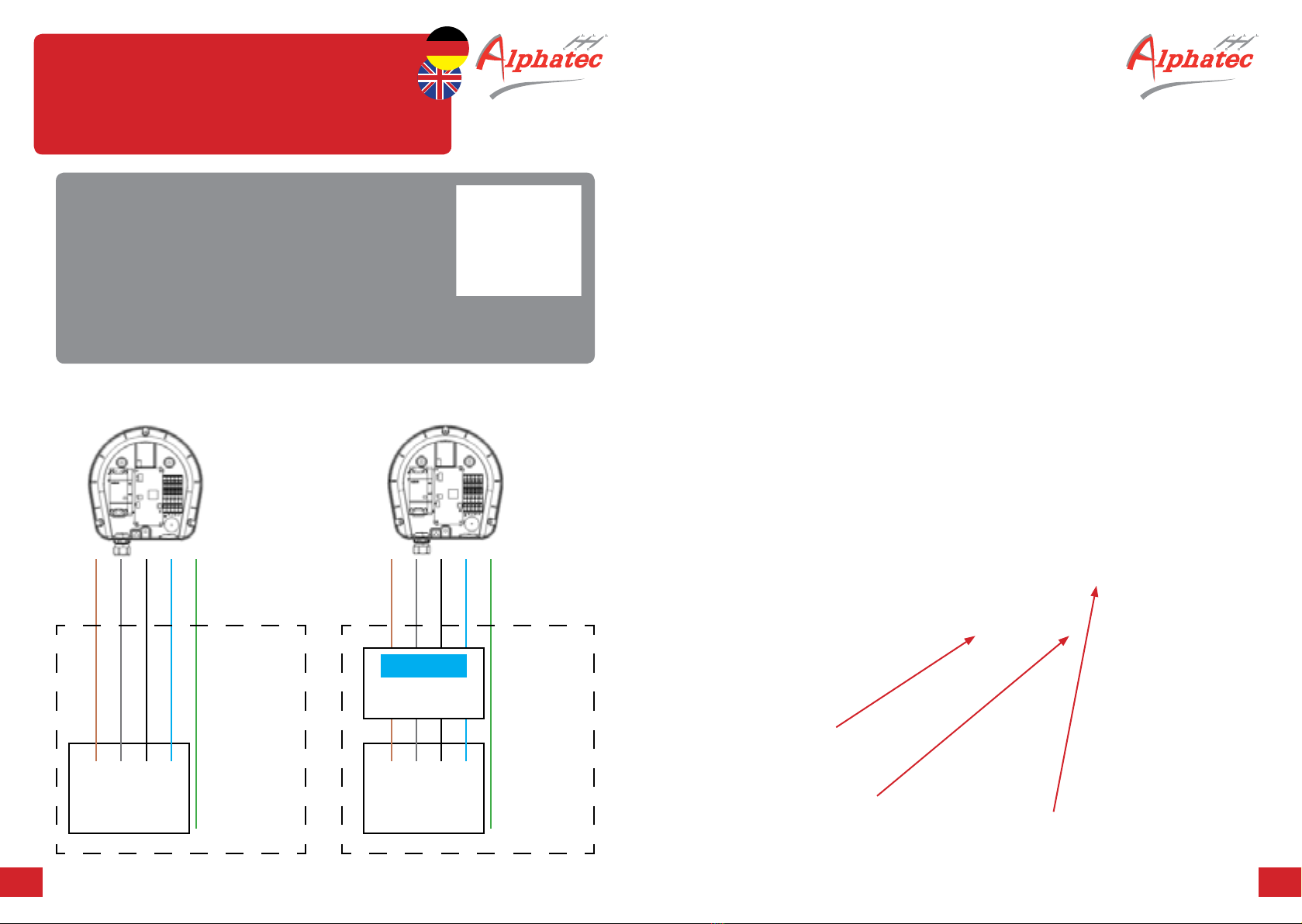
With some versions of the charging point, one or more RCDs
(RCD, 30mA or RCD 6mA) are also directly installed in the charging
device. Even in such cases the supply line, which can then be
a common line for two charging points, must be protected by miniature
circuit breakers LS (MCB) or ideally FI and LS (RCD + MCB).
Each charging point then also has its own FI (RCD, Type B or A+)
within the pole.
It is very important that the equipment and the housing parts are well
grounded. The earthing must be checked by a qualied electrician
during installation. Depending on the installation site, the necessary
measures for lightning protection must be evaluated If necessary,
additional lightning protection devices must be installed in the buildings
or the existing pre-installation.

Technische Änderungen unter Vorbehalt| Stand 03/2022| DB9.0029 Technische Änderungen unter Vorbehalt| Stand 03/2022| DB9.0029
14 15
Handbuch |
Wallbox Mini
Installation und Handhabung
Geeignete Orte für die Installation
Bitte beachten Sie, dass der richtige Ort für die
Installation dort sein sollte, wo sich der Lade-
eingang des gewählten Fahrzeugs bendet.
Es wird empfohlen, dass das angeschlossene
Kabel nicht zum Stolpern führen sollte.
Bitte beachten Sie auch, dass direkte Sonnen-
einstrahlung zu einer Verringerung des Ladestroms führt,
wenn die interne Wärme automatisch den Strom verringert,
solange das Ladegerät abkühlt.
Das Produkt besteht aus schwer entammbarem
Kunststo. Für die Montage an Holzwänden oder
anderen feuergefährdeten bzw. hitzeempndlichen
Oberächen empehlt sich die Verwendung einer
Metallwandplatte oder der verfügbaren Säule aus
pulverbeschichtetem Edelstahl.
Das Ladegerät ist besonders für den privaten
oder halböentlichen Bereich geeignet. Die Vandalismusbeständigkeit
ist nur bedingt gegeben (IK08). Je nach Ausstattung sind für jeden
Ladepunkt RCD (FI) Typ A installiert, MID-Zähler und Fehlerstrom-
detektoren sind integriert. Weitere Ausstattungen oder andere Typen
und Zubehör nden Sie auf unserer Website.
Es handelt sich um ein elektrotechnisches Produkt, das bei der Nutzung
Abwärme erzeugt. In der warmen Jahreszeit und bei Betrieb unter
Volllast kann sich das Gerät daher erwärmen. Die integrierte Temperatur-
messung reduziert dann die mögliche Ladeleistung. Um dies zu
vermeiden, wird dringend empfohlen, das Ladegerät nicht an einem Ort
zu installieren, an dem es extremer Sonneneinstrahlung ausgesetzt ist.
Manual |
Wallbox Mini
Installation and operation
Place of installation
Please be aware that the right place for Installation
should be where the charging inlet to the choosed car
will be. It is recommended that the connected cable
should not lead to stumbling.
Please also consider that exposure to direct
sunlight will lead to reduced charging current
when the internal heat decrease automatically
the current as long as the charger cooles down.
The product consists of ame-retardant plastic.
For installation on wooden walls or other re prone or
heat-sensitive surfaces, the use of a metal wall plate
or the available pillar made of powder-coated special
steel is recommended.
The charger is particularly suitable for private
or semi-public use vandalism resistance is only
limited (IK08). Depending on the equipment,
RCD (FI) type A are installed for each charging point,
MID meters and residual current detectors are integrated.
Other equipment or other types and accessories can be
found on our website.
This is an electrotechnical product which generates waste heat
when used. In the warm season and when operating under full load,
the device can thus heat up. The integrated temperature measurement
then reduces the possible charging power. To avoid this, it is strongly
recommended to not install the charger in a place where it is exposed
to extreme solar radiation.

Technische Änderungen unter Vorbehalt| Stand 03/2022| DB9.0029 Technische Änderungen unter Vorbehalt| Stand 03/2022| DB9.0029
16 17
Handbuch |
Wallbox Mini
Installation und Handhabung
Empfohlene Werkzeuge für die Installation
• Abgewinkelter Schraubendreher
• Schraubendreher Torx TX20
• Schraubendreher für Schlitzschrauben
• E-Mobilitätsprüfsimulator
• Erdanschluss- und RCB-Auslöseprüfgeräte
• im Optimalfall zusätzlich: Thermobildkamera zur Überprüfung
von verlustarmen Anschlüssen der Zuleitungen.
Bohrbild / drill pattern
92
133
1400
Manual |
Wallbox Mini
Installation and operation
Recommended tools for installation
• angled screwdriver
• screwdriver Torx TX20
• screwdriver for slotted screws
• e-mobility test simulator
• earth connection and RCB tripping test equipment
• in best case additional: thermal imaging camera
to check low-loss connections of the supply lines
Bohrbild / drill pattern
219,3
Ø 221 83,2

Technische Änderungen unter Vorbehalt| Stand 03/2022| DB9.0029 Technische Änderungen unter Vorbehalt| Stand 03/2022| DB9.0029
18 19
MID / meter
• Typen mit
integriertem
MID-Zähler
erhältlich
• types with
integrated
MID meter
available
alternativ:
RCBO (FI / LS)
Typ A / 3ph
32A, C Typ
alternativ:
RCBO (FI / LS)
Typ A / 3ph 32A,
C Typ Supply line with
RCD Typ A
Supply line with
RCD Typ A
L1L1 L2L2 L3L3 NN
Anschließen der Anschlußklemmen
Bei den Anschlußklemmen handelt es sich um
Steckklemmen. Bei Installation an einer Haushalts-
steckdose ist der Zuleitungsquerschnitt zu beachten.
Connecting the terminals
The terminals are plug clamps. Note the cable
cross-section, when installed to a household socket.
Handbuch |
Wallbox Mini
Installation mit Hausanschluss /
Installation with a domestic outlet
• Kabelzugang von unten
• Opening for cable from the bottom
• Eingang für optionale Tastensperre
• Entreance for optional key lock
• Kabelzugang von hinten durch
nachträgliches Önen möglich
• Openening for cable from the rear (optional)
mit RCB (FI) /
with RCB (FI)
mit RCB + Zähler
with RCB + meter

Technische Änderungen unter Vorbehalt| Stand 03/2022| DB9.0029 Technische Änderungen unter Vorbehalt| Stand 03/2022| DB9.0029
20 21
Handbuch |
Wallbox Mini
Installation Schritt für Schritt /
Installation step by step
1. Abdeckung önen / remove cover
• Önen Sie die drei Schrauben von hinten,
um die Abdeckung zu entfernen
• Open 3 screws from the rear to remove the cover
Schrauben an Rückseite /
Screws on the rear
3x
2. Wandbefestigung / wall attachment
• Verwenden Sie 3 Schrauben, um die Box an der Wand zu
befestigen. Verwenden Sie je nach Wandmaterial die
beiliegenden Schrauben und Kunststodübel
• Use 3 screws to x the box to the wall. Depending on the
wall material use the enclosed screws and plastic dowels.
• Schließen Sie die Stromquelle gemäß den örtlichen
Normen und Gesetzen an die Klemmen an.
Stellen Sie sicher, dass die Anschlüsse fest
und korrekt sind.
• Connect the power source according to local
standards and laws to the clamps. Ensure
that the connections are tight and correct.
Empfohlene Önung für Stromquelle
und BUS-Kabel (externern Schalter) /
recommended opening for power
source and BUS-cable (external switch)

Technische Änderungen unter Vorbehalt| Stand 03/2022| DB9.0029 Technische Änderungen unter Vorbehalt| Stand 03/2022| DB9.0029
22 23
Handbuch |
Wallbox Mini
Installation Schritt für Schritt /
Installation step by step
3. Wiederverschluss / reclosure
• Legen Sie die Abdeckung wie in der Zeichnung unten dargestellt
am horizontalen Rand an und schließen Sie sie vorsichtig.
Stellen Sie sicher, dass das Gerät korrekt befestigt und komplett
dicht geschlossen ist.
• Put the cover back on as shown on the depiction below and
close it up carefully. Make sure the product is mounted correctly
and closed completely so ensure the waterproofness.
4. Deckelverschraubung / lid xation
• Befestigung des Deckels mit 3 Torxschrauben von
hinten. Wenden Sie beim Anziehen der Schrauben
nicht zu viel Kraft an. Der Deckel muss vollständig
und ohne sichtbaren Abstand zur Basis
geschlossen sein.
• Fixation of the cover with 3 torx screws from the rear. Do not use too
much forcen, when tightening the screws. The cover must be closed
completely and without any visible gap between lid and base.
Information
• Die Schrauben benden sich auf der Rückseite,
um das Önen des Ladegeräts durch Unbefugte
zu erschweren. Für die Installation wird die
Verwendung eines Winkelschraubendrehers
o.ä. empfohlen.
• Screws are from rear to make it more dicult
for unauthorized person to open the charger.
For installation it is recommended to use an
oset screwdriver or similar.
• Achten Sie darauf, dass
beide Teile um die Trennlinie
herum vollständig
geschlossen sind
• Make sure, that both parts
are completely closed
without any gap

Technische Änderungen unter Vorbehalt| Stand 03/2022| DB9.0029 25
Technische Änderungen unter Vorbehalt| Stand 03/2022| DB9.0029
24
Handbuch |
Wallbox Mini
Erstinspektion /
Initial inspection
• Önen Sie 2 Schrauben von der Unterseite und 2 Schrauben
von der Oberseite, um die Tür zu entfernen
• Open 2 screws from the bottom side and 2 screws from
the topside to remove the door
1. Optische Prüfung / visual inspection
• Gehäuse, Sockel, Fundament, die Verschraubung der
Komponenten sowie Ladekabel und Ladebuchsen dürfen
keine sichtbaren Schäden aufweisen.
• Housing, base, foundation, the screw connection of the
components as well as charging cables and charging
sockets should not exhibit any visible signs of damage.
2. Funktionstest / functional test
• Verwenden Sie den Adapter zur Fahrzeugsimulation,
um die einwandfreie Funktion zu überprüfen.
Führen Sie alle relevanten Ladevorgänge durch.
• Use the adapter for vehicle simulation to check the faultless
function. Run through all relevant charging sequences.
3. Messungen / measurment
• Prüfung und Messung der Schutzeinrichtungen.
• Testing and measuring of the protective devices.
4. Schriftlicher Bericht / written report
• Die Ergebnisse der Inspektion, der Funktionsprüfungen und der
Messungen sind zu dokumentieren und in der Produkt- und Instal-
lationsakte abzulegen.
• Results of the inspection, functional tests and measurements are to
be documented and led in the product and installation le.
Handbuch |
Wallbox Mini
Einstellen des Maximal-Stroms /
Maximum current adjustment
• Das Einstellen einer Strombegrenzung ist mit dem integrierten
Drehschalter einfach möglich. Dies darf nur von einer Elektro-
fachkraft durchgeführt werden. Der maximale Strom wirkt sich
auf die gesamte Installation, die Stromquelle und das Lade-
verhalten aus. Sie dürfen keine Änderungen an der Einstellung
ohne Ihren Elektriker vor Ort vornehmen.
• It is possible to set a current limit by using the on board
rotary switch. This should only be performed by a qualied
electrician or ordered with maximum setting. The maximum
current aects the whole installation, power source and
charging behavior. You shall not attempt any changes
to the setting without your local electrician.
3 phase 1 phase General
1 - 6A A - 18A 0
2 - 7A B - 20A
3 - 8A C - 25A
4 - 9A D - 32A
5 - 10A
6 - 13A E - free
7 - 14A
8 - 15A F - slave
9 - 16A

Technische Änderungen unter Vorbehalt| Stand 03/2022| DB9.0029 Technische Änderungen unter Vorbehalt| Stand 03/2022| DB9.0029
26 27
Schritt für Schritt
1. Stellen Sie sicher, dass die Stromquelle
abgesteckt ist.
2. Drehen Sie den Drehschalter mit einem
kleinen Schraubendreher auf die korrekte
Position (vgl. Tabelle).
3. Schließen Sie die Abdeckung wieder.
4. Stellen Sie die Stromzufuhr wieder her.
Die Einstellungen werden nach dem Neustart
automatisch übernommen, wie im Falle
eine Stromausfalles.
5. Verbinden Sie den Ladestecker mit dem
Test-Simulator oder reinem Fahrzeug,
das beim Laden den Stromuss anzeigt.
6. Gleichen Sie die Einstellungen mit dem
tatsächlichen Stromuss ab.
LED-Anzeige der
Einstellungen während
der Boot-Sequenz:
Die blaue Blinksequenz
zeigt die Zehnerstelle,
die grüne Blinksequenz
zeigt die gewählte
Einerstelle des Stromes.
Handbuch |
Wallbox Mini
Einstellen des Maximal-Stroms
3 phase 1 phase General
1 - 6A A - 18A 0
2 - 7A B - 20A
3 - 8A C - 25A
4 - 9A D - 32A
5 - 10A
6 - 13A E - free
7 - 14A
8 - 15A F - slave
9 - 16A
z. B.
32 Ampere = 3 lange
Blinkzeichen blau und
2 Blinkzeichen grün (kurz)
15A = 1 x blue / 5 x green
LED display of the
settings during the
boot sequence:
The blue ashing
sequence shows the
tens digit, the green
ashing sequence
shows the one digit
of the current.
Step by step
1. Ensure that the power source is disconnected.
2. Turn the rotary switch with a small srewdriver
to the correct position (see table).
3. Close the cover.
4. Enable the power source. The settings
will be active after a reboot of the
charger after a power-o.
5. Connect the charger to the test-simulator or
a car which shows the current while charging.
6. Control the settings with the real current.
Manual |
Wallbox Mini
Maximum current setting
3 phase 1 phase General
1 - 6A A - 18A 0
2 - 7A B - 20A
3 - 8A C - 25A
4 - 9A D - 32A
5 - 10A
6 - 13A E - free
7 - 14A
8 - 15A F - slave
9 - 16A
z. B.
32 Ampere = 3 lange
Blinkzeichen blau und
2 Blinkzeichen grün (kurz)
15A = 1 x blue / 5 x green

Technische Änderungen unter Vorbehalt| Stand 03/2022| DB9.0029 Technische Änderungen unter Vorbehalt| Stand 03/2022| DB9.0029
28 29
Handbuch | Wallbox Mini
Verbindung mit externer Steuerung
Connection to external control
K204 (LED with Resistors):
1: +SV
2: G
3: G
4: B
Bus RS
485: K400:
1: RS485B
2: GND
3: RS485A
K401 ( 5V, 1mA):
1: Relais in
2: Realis out
(open drain)
DC RCM
K202:
1: GND
2: +12V
3: RCM_test
4: RCM_fault
Socket with
Aktuator
K200:
1: LOCK_POS
2: SCL
3: SDA
4: Motor_A
5: Motor_B
6: GND
I2C Interface, 5 V
2: SCL
3: SDA
6: GND
K100 (Power IN):
1: L
2: N
3: L_OUT
4: PE (=GND)
Cont L
earth
N
L1
Fuse, 1 A max
1933-100100 EV-Controller, basic
CP
PP
Welding
detection
K201:
1: GND
2: WELD
Information
• Nutzen Sie den RS 485 / Modbus Bus für
die Verbindung mit externen Steuerungen.
• Use the RS 485 / Modbus Bus connection
for external control.
Bus RS 485: K400:
1: RS485B
2: GND
3: RS485A
Information
• Über ein externes oder internes Relais am
K401 kann das Ladegerät seinen Ladestrom
auf ein Minimum reduzieren, z. B. auf 6 A
(Eco-Modus), wenn eine Photovoltaikanlage
nicht genügend Strom liefern kann.
Für weitere Informationen wenden Sie sich bitte
an den Hersteller oder Ihren örtlichen Elektriker.
• With the input from an external or internal Relay on K401,
the charger can reduce it´s charing current to minimum
e.g. 6A (eco-mode) for example when a Photovoltaic
system cannot provide enough current.
For more detailed information contact the manufacturer
or your local electrician.
Bus RS 485: K400:
1: RS485B
2: GND
3: RS485A
K401 ( 5V, 1mA):
1: Relais in
2: Realis out
(open drain)
Welding
detection K201:
1: GND
2: WELD

Technische Änderungen unter Vorbehalt| Stand 03/2022| DB9.0029 Technische Änderungen unter Vorbehalt| Stand 03/2022| DB9.0029
30 31
Handbuch |
Wallbox Mini
Verbindung zu externer Steuerung
Manual |
Wallbox Mini
Connection to external control
So ändern Sie die Modus-ID:
1. Schreiben Sie eine neue ID für die Adresse 6
2. Lesen Sie zur Überprüfung die Adresse 6
3. Schreiben Sie 1 an Adresse 7 um sie im EEPROM zu speichern
4. Schreiben Sie 1 an Adresse 8 um neu zu starten
how to change the mode-ID:
1. Write new ID for address 6
2. Read address 6 for checking
3. Write 1 to address 7 to save it in the EEPROM
4. Write 1 to address 8 to reboot
Information
Verwenden Sie den Busabschlusswiderstand bei Gruppen
von Ladegeräten, welche am Ende der verbundenen Gruppe
mit dem Bus verbunden sind.
Information
Use the bus terminating resistor for groups of chargers that
are connected to the BUS at the end of the connected group.
Bus RS
485: K400:
1: RS485B
2: GND
3: RS485A
Bus RS
485: K400:
1: RS485B
2: GND
3: RS485A
Programmier Adapter:
K203 (ISP):
Würth 490107670612
(nicht onboard)
1: MISO
2: +SV
3: SCK
4: MOSI
5: RES#
6: GND
Programming Adapter:
K203 (ISP):
Würth 490107670612
(not onboard)
1: MISO
2: +SV
3: SCK
4: MOSI
5: RES#
6: GND
K401 ( 5V, 1mA):
1: Relais innen
2: Realis aussen
(oene Senke)
K401 ( 5V, 1mA):
1: Relais in
2: Realis out
(open drain)

Technische Änderungen unter Vorbehalt| Stand 03/2022| DB9.0029 Technische Änderungen unter Vorbehalt| Stand 03/2022| DB9.0029
32 33
Handbuch |
Wallbox Mini
Busregister und Funktionen /
BUS register and functions
Parameter lesen – READ HOLDING REGISTERS
(0 x 0,3) verwenden /
read parameters – use READ HOLDING
REGISTERS (0 x 0,3)
Adresse /
address Parameter / parameter
0EVSE Status: 1 bereit, 2 verbunden, 3 laden /
EVSE status: 1 ready, 2 connected, 3 charging
1tatsächlicher Modbus ID; Standard 1 /
actual modbus ID; standard 1
2installierte Verstärker (vom Drehschalter lesen) /
installed amplier (read rotary switch)
3Entsperren erzwingen (immer 0) /
force unlock (always 0)
40 = Ladestation aktiviert; 1 = deaktiviert /
0 = charging station activated; 1 = deactivated
5gedrosselt A /
reduced A
6neue Modbus ID /
new modbus ID
7Schreiben von neuer ID in das EPROM /
new ID in EPROM writing
8Reboot-Einheit, immer 0 /
reboot-unit; always 0
Parameter schreiben – WRITE MULTIPLE
PARAMETERS (0 x 10) verwenden /
write parameters – use WRITE MULTIPLE
PARAMETERS (0 X 10)
Adresse /
address Parameter
0N/A (schreibgeschützt) /
N/A (read-only)
1N/A (schreibgeschützt) /
N/A (read-only)
2N/A (schreibgeschützt) /
N/A (read-only)
31 = Entsperren erzwingen /
1 = force unlock
40 = Ladestation aktiviert; 1 = deaktiviert /
0 = charging station activated; 1 = deactivated
5tatsächliche Ampere einstellen; muss höher als 6A sein /
set actual amps; has to be over 6A
6schreiben einer neuen Modbus-ID /
writing of a new modbus ID
70 = keine Aktion; 1 Parameter 6 in EPROM schreiben /
0 = no action; writing 1 parameter 6 in EPROM
80 = keine Aktion, 1 Einheit startet neu /
0 = no action; reboot of one unit
Adresse / address Darstellung / description
0, 1, 2, 4, 5, 6 integer 16-Bit
7, 8 boolean (0/1)

Technische Änderungen unter Vorbehalt| Stand 03/2022| DB9.0029 Technische Änderungen unter Vorbehalt| Stand 03/2022| DB9.0029
34 35
Handbuch |
Wallbox Mini
Busregister und Funktionen /
BUS register and functions
Information
• Es ist auch möglich die Überwachung und die
Abänderung der BUS Einstellungen mit Standard-
programmen wie QModBus und RS485 Converter
vorzunehmen. z.B. DSD TECH oder Model SH-U10.
Natürlich können auch andere marktübliche Programme
oder Konverter verwendet werden.
Zum besseren Verständnis haben wir die Basisstrukturen
dieser Programme im Folgenden dargestellt.
• For BUS monitoring and changing the settings it is possible
to use standard programs like QmodBus and USB to RS485
Converter. e.g. DSD TECH or Model SH-U10.
It is also possible to use any other relevant program
or converter. There are plenty of them on the market.
For better understanding the basic structure of these
kind of programs is shown in the following.
BUS Verbindung / BUS connection
Baudrate / baud rate 9600
Parität / parity keine / none
Stopbits / stop bits 1
Data Bit / data bit 8
Standard Kommunikationsrahmen /
standard communication frame
1. Protokol: Modbus RTU (HEX) /
protocol: modbus RTU (HEX)
2. 8-Bit Slave-Adresse (0 x 01) /
8-bit slave address (0 x 01)
3. Funktionsmodus (z.B. 0 x 0,3 / 0 x 10) /
function mode (e.g. 0 x 0,3 / 0 x 10)
4. N x 8 Bit-Daten – Registeradresse (16 Bit); Anzahl der Spulen
(16 Bit, z.B. 0 x 09 für alle Register, die mit der Adresse 0 x 00
beginnen); tatsächliche Daten (z.B. 16 Bit integer) /
N x 8 bit data – register address (16 bit); number of coils
(16 bit, e.g. 0 x 09 for all registers if starting with address 0 x 00);
actual data (e.g. 16 bit integer)
5. 16 Bit zykilische Redundanzprüfung (CRC)
zur Benachrichtigungsverizierung /
16 bit cyclic redundary check (CRC) for message verication

Technische Änderungen unter Vorbehalt| Stand 03/2022| DB9.0029 37
Technische Änderungen unter Vorbehalt| Stand 03/2022| DB9.0029
36
Handbuch |
Wallbox Mini
Busregister und Funktionen /
BUS register and functions
Handbuch |
Wallbox Mini
Externer Schalter /
External switch
Information
• Klemmgehäuse für optionalen Anschluss mit
externem Schalter, Tastensperre oder externem
Relais. Diese Funktion schaltet das Ladegerät
vollständig aus, wenn das externe Relais oder
der Schalter geönet wird.
Um diese Funktion zu nutzen, entfernen Sie die Brücke wie in
der Abbildung (nächste Seite) gezeigt und verbinden Sie anstelle
der Brücke den umschaltbaren Ausgang des Relais oder der
Tastensperre.
Wenn die Kontaktbrücke geönet ist, ist das Ladegerät aktiv, kann
jedoch nicht mit dem Laden beginnen, da die Kommunikation mit
dem Fahrzeug unterbrochen ist.
• Terminal housing for an optional connection to an external switch,
key lock or an external relais. This function turns o the charging
station completely, if the external realis or the switch are opened.
To use this feature remove the bridge as shown in the depiction
below. Connect the switchable exit of the relais or de key lock
instead.
The charging device is active when the contact bridge,
but no charging action is possible, because of the disruption of
the communication with from wallbox to vehicle.

Technische Änderungen unter Vorbehalt| Stand 03/2022| DB9.0029 Technische Änderungen unter Vorbehalt| Stand 03/2022| DB9.0029
38 39
Handbuch |
Wallbox Mini
Externer Schalter /
External switch
• Klemmbrücke in
geschlossenem Zustand
• bridge in closed state
• Klemmbrücke entfernt
• bridge removed
• Relais oder Tastensperre
kann nun angeschlossen werden
• relais or key lock can now
be connected
Handbuch |
Wallbox Mini
Wartung und Pege /
Maintenance and cleaning
• Nach DGUV V3 ist der Betreiber elektrischer Anlagen gesetzlich
verpichtet, die Anlagen auf ihren funktions- und sicherheits-
technisch einwandfreien Zustand hin zu überprüfen.
• According to DGUV V3, the operator of electrical equipment is
legally obliged to check the systems to ensure that they are in
proper condition with regard to functionality and safety.
Wartungszeitpunkte / maintenance times
• Bei der ersten Prüfung vor der Inbetriebnahme
• Through initial testing before commissioning
• Durch regelmäßig durchgeführte periodische Inspektionen
• Through periodic inspections conducted regularly
• Nach jeder Änderung oder Reparatur
• After each modication or repair
Achtung! / Caution!
• Installation und Wartung dürfen nur von
qualizierten Elektrofachkräften durchgeführt
werden. Im Falle eines Verstoßes gegen diese
Vorschrift erlischt die Gewährleistungspicht
des Herstellers mit sofortiger Wirkung.
• Installation and maintenance should only be
carried out by qualied electrical contractors. In the event of a
breach of this requirement, the manufacturer’s warranty obligations
shall expire with immediate eect.
This manual suits for next models
17
Table of contents
Other Alphatec Batteries Charger manuals
Popular Batteries Charger manuals by other brands

EXICOM POWER SOLUTIONS
EXICOM POWER SOLUTIONS Harmony Series troubleshooting guide

Hawker
Hawker Lifetech instructions

Quick
Quick SBC NRG+ Series Manual of installation and use

Bosch
Bosch GAL Professional 1880 CV Original instructions

DEFA
DEFA MultiCharger 1203 User and installation guide

Clas Ohlson
Clas Ohlson OY-340-5A manual