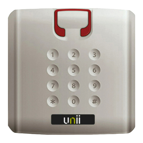
alphatronics UNii User manual

Quick start and installation guide
English manual page 2
Nederlandse handleiding pagina 13

2
Table of contents
Quick installation guide ........................................................................................................................................................3
Step 1: UNii manager ............................................................................................................................................................3
The login credentials for UNii manager.............................................................................................................................3
Step 3.1: Connecting to the panel.......................................................................................................................................3
Step 3.2: Programming the installer rights .......................................................................................................................4
Step 4: Connecting with the key..........................................................................................................................................4
UNii mounting and installation............................................................................................................................................5
Mounting .................................................................................................................................................................................5
Removal protection (only for grade 3) ...............................................................................................................................5
Connections............................................................................................................................................................................6
Inputs .......................................................................................................................................................................................6
Outputs ....................................................................................................................................................................................7
RS-485 bus .............................................................................................................................................................................7
Cable length RS-485 bus .....................................................................................................................................................7
Power .......................................................................................................................................................................................8
Backup power supply............................................................................................................................................................8
Protection against discharge...............................................................................................................................................8
Low battery voltage............................................................................................................................................................... 9
230V Mains connection........................................................................................................................................................9
Jumpers...................................................................................................................................................................................9
General...................................................................................................................................................................................10
Specifications .......................................................................................................................................................................10
Fuses......................................................................................................................................................................................11
Service....................................................................................................................................................................................11

3
Quick installation guide:
Congratulations with your UNii intruder panel! There are a few steps necessary to connect to the UNii to a
laptop/pc for programming.
Step 1: UNii manager
Programming the UNii intruder panel is done using the “UNii manager” software tool. The connection between the
UNii intruder panel and the laptop/pc is an IP connection via LAN.
Step 2: The login credentials for UNii manager
Installer version
User name: installer
Password: installer
End-user version
User name: user
Password: user
Step 3.1: Connecting to the panel
The UNii manager tool starts up in the main screen. In the ‘Select device’ part you can connect to the UNii
manually. By using the button ‘Search systems’ all UNii intruder panels on the network will be shown.
Select the desired UNii intruder panel, click “Connect” to establish a connection.

4
Step 3.2: Programming the Installer rights
By default, the installer does not have authorization to make a connection with the UNii, to ensure the installer can
make a connection the following steps are required:
1. Go to the User menu on the Keypad.
2. Enter the Administrator user code.
3. Scroll down and select “Maintenance”.
4. Go to the option “Installer access”.
5. Select “Rights”.
6. Choose the correct installer access level.
7. Installer and user rights.
8. Only installer rights.
9. You now must enter a “Time” that the installer has access, use the keys 1 - 9 to select the desired number
of hours on the keypad.
10. Click on the button “save”.
11. The installer now has access for the selected time.
Step 4: Connecting with the “key”
The connection between the UNii intruder panel and the UNii manager tool is secured by a key. The key can be
displayed on the keypad.
Where can you find the key?
Go to Menu -> Information -> UNii manager key.
The key that will be shown contains only the digits 0 to 9 and the letters A to F.
Keypad displays “<<< No Communication>>> “
If the keypad displays the message ‘No communication’ it is important to follow the next steps:
1. Short circuit the 2 pins DSW2 on the UNii mainboard temporarily, the software will now scan the RS-485
bus again to detect all devices.
2. After this it can take +/- 15 seconds for detecting the keypad.

5
UNii Mounting and installation
The UNii control panel is the heart of the security system to which all other components are connected. The UNii
control panel has an independent power and emergency power supply and is supplied in a metal housing suitable
for applications up to and including Security Grade 3.
Mounting
The metal enclosure must be securely fastened using 3 screws (4.2 x 60 mm) and suitable plugs. For a surface
other than brick, suitable screws and, if necessary, plugs must be used. The screw holes are located at the bottom
left and right of the cabinet and one slotted hole in the middle of the cabinet. See the figure below.
Mounting holes for the metal enclosure.
Removal protection (only for Grade 3)
First install the anti-tamper board in the metal enclosure, see illustration. Then mount the cabinet loosely on the
wall. Mark the hole of the anti-tamper board and remove the enclosure. Place the plug in the wall. Then mount the
metal enclosure securely on the wall. Then screw the anti-tamper board to the wall. Ensure that the screw head
precisely touches the anti-tamper board, do not over tighten it. The aim is that during a tamper attempt the middle
square breaks off, causing a tamper alarm. Mount one of the two wires of the tamper PCB on one input of the
control panel board and the other to a 0V connection. The input in must be programmed as a ‘tamper input’.
Mounting the anti-tamper board

6
Connections
1. Inputs
2. Outputs – relay and o.c.
3. Loudspeaker output
4. Siren output
5. LAN connection
6. RS-485 bus connection
7. Outgoing 12VDC power
8. Battery connection
9. Power connection
10. Tamper switch connection
11. LAN link and activity LED
12. Firmware LED (ON = OK)
13. RS-485 communication LEDs
14. Output expander connector
15. Input expander connector
16. Generic expander 3
17. Generic expander 2
18. Generic expander 1
19. Connection for temperature sensor
20. Jumpers
21. Opening for mounting expander
Inputs
8 zone inputs on the main PCB, zone inputs can be expanded to a maximum of 32 zones in the same enclosure by
means of an 8-input expander module (art. code 004664).

7
Outputs
-Speaker (LS) output 8-ohm 15W. The LS output has a polyfuse of 750 mA. In the programming (LS
monitoring) of the control panel it can be set that the LS output is monitored against tampering. If this
function is switched on, the loudspeaker itself functions as an End-Of-Line (EOL) resistor, no additional
resistor is required.
-Siren output 7W. The siren output has a polyfuse of 500 mA. In the programming (siren monitoring) of the
control panel it can be set that the siren output is monitored against tampering. If this function is switched
on, a 1k8 Ohm End-Of-Line (EOL) resistor must be placed in parallel over the siren terminals.
-2 potential-free relay contacts (maximum current through the contact is 750mA max. @ 30VDC)
-2 Open Collector (O.C.) outputs, maximum load per output is 200 mA. A cable of no more than 30 m may
be connected to these outputs. The OC outputs are provided with a polyfuse of 200 mA.
-3 connections for (outgoing) + 12V supply voltage, together with one polyfuse of 750 mA.
-1 connection for (outgoing) + 12V power supply via the RS-485 bus, equipped with a polyfused of 750 mA.
RS-485 bus
The UNii uses an RS-485 data bus to connect different bus components. The maximum cable length of an RS-
485 bus is 1,200 m. This distance can only be achieved when using the prescribed FTP cable (FTP = foiled twisted
pair, “shielded with twisted pairs”, data cable at least 2x2x0.5mm + shielding). Always ensure that the shielding of
the RS-485 cable is unilaterally connected to ground, for example in the control panel. Ground screws are
provided for this at the recess in the rear of the metal housing. A 4-core FTP cable is always made up of 2 pairs of
wires (for example red + blue twisted together and green + yellow twisted together), make sure that 1 wire pair (for
example red and blue) is used for the power supply (+ 12V and 0V) and the other conductor pair (for example,
yellow and green) for data communication (A and B). If the prescribed cable is not used, interference may occur
on the RS-485 data bus that negatively affects the system. With a long RS-485 bus (longer than approx. 500 m) it
is not allowed to make star connections between the UNii control panel and the other components. Ensure that all
components are connected in one line. The bus may never be longer than 1200 m.
All bus components must be addressed. This can be done in two ways, manually or automatically. Manually by
setting the address of each bus component itself (unique address on rotary switch or dip switches) or
automatically whereby the addresses are determined by the UNii itself. To do this, set all bus components to
address 0. Optionally, the assigned addresses can be adjusted afterwards with the help of UNii manager.
Cable length RS-485 bus
The maximum distance between a powered and not powered bus component depends on the resistance of the
cable and the power consumption of the relevant component. Consult the installation manual of the connected
components to find out the power consumption and minimum supply voltage. Example calculation: UNii keypad
with reader (art. code 004624/26):
Alphatronics RS-485 bus cable (art. code. 008653) has a resistance of 10Ω per 100m.
Minimum voltage for the keypad is 7.5 V and the power consumption when the keypad is active is 135 mA.

8
If the system is powered exclusively by the battery and it is almost empty, the supply voltage for the components
is still 10.8 V, the maximum voltage drop across the cables may therefore be 10.8 V - 7.5 V = 3.3 V.
=3,3
0,135=24,4Ω
For the total resistance, the resistance in the supply wires (+ and 0) must be added together. Based on standard
Alphatronics RS-485 bus cable, the cable to a keypad can therefore be a maximum of 100m long. If a greater
distance is desired, a cable with a lower resistance should be used.
In the table below the maximum cable lengths are shown for the bus cable starting from cable with a resistance
of 10Ω per 100m.
Component
Maximum cable length
Keypad with reader
120m
Keypad without reader
200m
Card reader interface with reader
170m
IO without own power supply
150m
KNX module
200m
Wireless interface Power G, Pyronix
150m
Wireless interface Elite
200m
Power
The + 12V (No. 7 in the drawing) connections and the RS-485 bus (No. 6 in the drawing) provide a continuous
supply voltage. RS-485 output between 8.9 and 14.8VDC and the +12V (AUX) output between 9,2 and 14,8VDC.
The minimum current consumption of both outputs is 0mA. The total continuous consumption taken (+ 12V
together with RS-485 bus) may never exceed 250 mA for a Grade 3 installation or 750 mA for a Grade 2
installation. The system must use alarm reporting to the monitoring station, whereby the minimum battery
autonomy time is 30 hours (Grade 3) or 12 hours (Grade 2).
The connections are equipped with a monitoring mechanism. If the voltage drops below 9.5 VDC, an "AUX LOW"
error message is generated.
If the voltage exceeds 17.5VDC, an error message "AUX HIGH" is generated, and the output voltage is switched
off.
Backup power supply
There is room for a 7Ah or 12Ah battery in the metal enclosure of the control panel. Please note for a Grade 3
installation, a 12Ah battery (for example Yuasa NP12-12) must be used. When used in a Grade 2 installation, it is
sometimes enough to use a 7Ah battery, this depends on the maximum current drain that is taken. A fully
discharged battery must be charged to at least 80% of the capacity within 24 hours. If applicable, the temperature
sensor must be stuck to the top of the battery with the supplied tape.
Protection against discharge
If the mains voltage stays away too long and the battery voltage becomes too low (below 10.1VDC), the pcb board
will switch itself off completely. You can only restart and charge the battery if the mains voltage is restored. The
voltage of the recommended 12Ah Yuasa battery is 9.7VDC with a deep discharge.

9
Low battery voltage
A low battery voltage is detected when the battery voltage drops below 11.0VDC (SD low voltage).
230V mains connection
A mains fuse with a value of 315 mA is included in the terminal block. The installation must be equipped with a
double-pole switch / disconnector in order to make the mains connection completely voltage-free.
The mains voltage is connected to the terminal block in the
cabinet. The middle connection is the earth connection, and this
connection is connected to the metal enclosure of the control
panel. The terminal block is equipped with a glass fuse. The earth
connection is also provided with an earth wire (yellow / green) with
a connection lip. This is intended to connect the lid of the metal
enclosure with the protective earth.
Ensure that this connection is properly connected when closing
the cabinet.
This equipment may only be installed by qualified personnel and must be kept out of
reach of children!
Always ensure that the alarm system is properly earthed. If there are doubts about the grounding, check it
carefully.
A good grounding is essential for the proper removal of electrical interference!
Jumpers
The main board has a row of pin headers (no. 20 in the drawing) on which a jumper can be placed. The
following jumpers can be useful during installation or when maintaining the system:
DSW0 Default jumper:
PIN-codes back to 6-digits
Installer (123456) and supervisor
(445566) back to default (also the name and profile)
Ethernet connection back to (DHCP)
DSW2 By short circuiting these 2 pins a new bus scan is performed.
DSW3 By short circuiting these 2 pins during a power-up the RS-Bus scan table is erased.
TAMP Tamper switch for metal enclosure can be bypassed!
RST By short circuiting these 2 pins the mainboard will restart.
Attention: All other pin headers must be left open and no jumpers placed!

10
General Specifications
Power: Type A (power supply with back-up facility)
PRIMARY: 230VAC ±10% / 50Hz ±10%. At full load the maximum primary consumption is 1,1 A
(@230VAC). Min. cable diameter 3 x 0,75mm.
SECUNDARY: 18VAC/3A (±3%), maximum ripple/noise after rectification is 250mV (peak-peak). The
power supply complies with EN50131-6 + A1
Own consumption: 100mA at 12VDC
Battery:12VDC trickle charge, maximum battery capacity 12Ah with 100% fully charged (Yuasa
NP12-
12). Ri max = 3,3Ωfor total I max = 250mA.
Aux power: 9,2 - 14,8VDC ripple max 120mV ( Imin = 0 A, Imax = 250mA (750mA zekering).
Min. cable diameter 2x 0,5mm2
RS-485 power: 8,9 - 14,8VDC ripple max 120mV (Imin = 0mA, Imax = 250mA (750mA zekering).
Min. cable diameter 2x2x0,5mm2+ earth wire
Ethernet: 10 / 100Mbit
Expansion:3 generic expander slots
Bus: RS-485 bus, maximum cable length 1200m
IP dialer: SecIP, SIA DC09 ATS category SP3 and DP4
Casing: Metal enclosure; 400mm x 250mm x 135mm (H x W x D). Weight: 5200gr excluding
battery.
Control panel cabinet must be installed within the protected area. The maximum depth
(thickness) of the battery is 100 mm.
Manufacturer: Alphatronics BV
Security Grade: Grade 3, if a wireless expansion is used, Grade 2.
Test institute: The testing in accordance with necessary standards was carried out by Kiwa /
Telefication BV, the Netherlands
EMC: EN50131-4:2011 + A1:2014
Power supplies: EN50131-6:2017
Safety: EN IEC 62368-1:2014 + A11:2017
Security: EN50131-3:2009, EN50131-1:2006 + A1:2009 + A2:2017 according to Grade 3 and
environmental class II.
Radio: EN50131-5:2017 EN303 446 V1.1.0, EN301 489-1/52 EN55032
Transmission: EN50131-10:2014, EN50136-2:2013
Removal protection:Is mounted if applied in a Grade 3 installation. Is necessary for Grade 3
compliance.Print dimensions: 55mm x 35mm (L x W). Weight: 10gr.
Operating temp.: 0° C tot +40° C
Storage temp.: -20° C tot +60° C
Humidity: 85% relative humidity at 30° C
Environment: Indoor use only

11
Fuses
The pcb board has several polyfuses and two glass fuses.
F1: 750mA (polyfuse) protects the 3 outgoing +12V connections.
F2: 750mA (polyfuse) protects the LS output.
F3: 750mA (polyfuse) protects the +12V connection of the outgoing RS-485 bus.
F4: 500mA (polyfuse) protects the internal +3V3 power supply.
F7: 200mA (polyfuse) protects the OC3 output.
F8: 200mA (polyfuse) protects theOC4 output.
F9: 500mA (polyfuse) protects the siren output.
F10: 200mA (polyfuse) protects the output expander.
F11: 200mA (polyfuse) protects generic expander 1.
F12: 200mA (polyfuse) protects generic expander 2.
F13: 200mA (polyfuse) protects generic expander 3.
Battery: 5A (glass fuse 6x 32mm)
230V: 315mA (glass fuse 5 x 20mm)
Service
The UNii keypad has no serviceable parts or adjustment points. In the event of established defects, the entire
keypad must be replaced (in consultation with the support desk). The battery has an expected lifetime of 3-5
years and must be checked (and replaced if necessary) every year during maintenance.
Identification
A label has been fixed to the back on the inside of the metal enclosure, based on which the device can be
identified. The label includes the name of the manufacturer, the model, a production date (2 digits for the month,
followed by 2 digits for the year), the security Grade and the environmental class.
-Labels may not be removed!
-If the installation does not comply with Grade 1, 2 or 3, the labels MUST be removed or made clear in
another way that the installation is non-compliant!
-The serial number must not be removed.

12
Inhoudsopgave
UNii Quick start ....................................................................................................................................................................13
Belangrijk voor de installatie..............................................................................................................................................13
Stap 1: UNii manager ..........................................................................................................................................................13
Stap 2: Het inloggen voor UNii manager.........................................................................................................................13
Stap 3: Het verbinden..........................................................................................................................................................13
Stap 3.1: Installeur rechten instellen................................................................................................................................14
Stap 4: Het verbinden met de sleutel ...............................................................................................................................14
Montage.................................................................................................................................................................................15
Afneem beveiliging (alleen voor grade 3) ........................................................................................................................15
Aansluitingen ........................................................................................................................................................................16
Ingangen................................................................................................................................................................................16
Uitgangen ..............................................................................................................................................................................17
RS-485-bus ..........................................................................................................................................................................17
Voeding..................................................................................................................................................................................18
Noodstroomvoorziening.....................................................................................................................................................18
Beveiliging tegen diepontlading ........................................................................................................................................19
Lage batterijspanning .........................................................................................................................................................19
230V netaansluiting.............................................................................................................................................................19
Jumpers.................................................................................................................................................................................19
Specificaties..........................................................................................................................................................................20
Zekeringen.............................................................................................................................................................................20
Service....................................................................................................................................................................................21

13
UNii Quick start
De UNii centrale is het hart van het beveiligingssysteem waarop alle overige componenten worden aangesloten.
De UNii centrale heeft een zelfstandige spannings- en noodstroomvoorziening en wordt geleverd in een metalen
behuizing geschikt voor toepassing t/m Security Grade 3.
BELANGRIJK VOOR DE INSTALLATIE:
Gefeliciteerd met de aankoop van de UNii! Er zijn een paar stappen die er gevolgd moeten worden voor de juiste
installatie en de verbinding.
Stap 1: UNii manager
De programmering van de UNii gebeurt via de “UNii manager” softwaretool. De verbinding tussen de UNii centrale
en de laptop/pc is een IP-verbinding over LAN.
Stap 2: Het inloggen voor UNii manager
Voor de installateursversie geldt:
Gebruikersnaam: installer
Wachtwoord: installer
Voor de gebruikersversie geldt:
Gebruikersnaam: user
Wachtwoord: user
Stap 3: Het verbinden
UNii manager start op in het home scherm. In het ‘Selecteer apparaat’
gedeelte kan de UNii centrale handmatig verbonden worden.
Door middel van de ‘Zoeksystemen’knop worden alle UNii centrales op
het netwerk getoond.
Selecteer de gewenste UNii centrale en druk op ‘Verbind’.

14
Stap 3.1: Installateur rechten instellen
Om de installateurs rechten in te stellen op de UNii zijn de volgende stappen nodig:
Ga naar het menu op het Keypad.
Vul de gebruikers code in.
Scrol naar beneden, ga naar “Onderhoud”.
Ga naar “Toegang installateur”.
Druk op “Rechten”.
Selecteer de juiste installateur rechten.
Rechten voor installateur en gebruiker.
Enkel installateurs rechten.
Hierna moet de tijd in uren via “Tijd” worden ingesteld, kies 1 - 9 op het keypad.
Druk op de knop “opslaan”.
De installateurs account is nu actief voor de ingestelde tijd.
Stap 4: Het verbinden met de sleutel
De verbinding tussen de centrale en de UNii manager programmeertool wordt beveiligd met een sleutel. De sleutel
wordt via het keypad getoond.
Waar kunt u de sleutel vinden?
Ga naar Menu -> Informatie -> UNii manager sleutel.
De sleutel die hier wordt afgebeeld bevat alleen de cijfers 0 t/m 9 en de letters A t/m F.
Keypad geeft “<<< No Communication>>> “melding
Als het UNii keypad deze melding geeft zijn de volgende stappen belangrijk om te volgen:
Maak op de print kortstondig verbinding tussen de pinnen bij “DSW2”
Door de pinnen kort te sluiten wordt een bus scan uitgevoerd.
Hierna zal het +/- 15 sec duren tot het keypad wordt herkend.

15
Montage
De kast dient met behulp van 3 schroeven (4,2 x 60mm) en passende pluggen degelijk bevestigd worden. Bij een
andere achtergrond dan steen, dienen daartoe geschikte schroeven en eventueel pluggen gebruikt te worden. De
schroefgaten bevinden zich links en rechtsonder in de kast en één slob gat midden boven in de kast. Zie
onderstaande figuur.
Montage gaten voor de kast.
Afneem beveiliging (alleen voor Grade 3)
Monteer eerst de anti-sabotage print in de kast, zie illustratie. Monteer vervolgens de kast losjes aan de wand.
Teken het gat van de anti-sabotage print af en verwijder de kast. Plaats de plug in de wand. Monteer daarna de
kast stevig aan de wand. Schroef vervolgens de anti-sabotage print vast aan de wand. Zorg ervoor dat de
schroefkop de anti-sabotage print precies raakt, zet deze niet te vast. Het doel is, dat bij een sabotagepoging het
middelste vlakje afbreekt, waardoor sabotage optreedt. Monteer één van beide draden van het sabotage printje op
een ingang en de andere op een 0V aansluiting.
Montage anti-sabotage print

16
Aansluitingen
1. Ingangen
2. Uitgangen – relais en o.c.
3. Luidspreker uitgang
4. Sirene uitgang
5. LAN aansluiting
6. RS-485 bus aansluiting
7. Uitgaande 12VDC voeding
8. Accu aansluiting
9. Voedingsaansluiting
10. Sabotage schakelaar aansluiting
11. LAN link en activiteit LED
12. Firmware LED (AAN = OK)
13. RS-485 communicatie LEDs
14. Output expander connector
15. Input expander connector
16. Generic expander 3
17. Generic expander 2
18. Generic expander 1
19. Aansluiting voor temperatuur sensor
20. Jumpers
21. Opening voor montage expander
Ingangen
8 zone ingangen op de hoofdprint, zone ingangen zijn uit te breiden tot max. 32 zones in dezelfde behuizing
met behulp van een 8-ingangen expansieprint (art.nr. 004664).

17
Uitgangen
Luidspreker (LS) uitgang 8 ohm 15W. De LS-uitgang is voorzien van een zelfherstellende zekering van
750mA. In de programmering (LS-bewaking) van de centrale kan ingesteld worden dat de LS-uitgang
wordt bewaakt tegen sabotage. Indien deze functie wordt aangezet dan functioneert de luidspreker zelf
als Einde-lus (EOL) weerstand, er is geen extra weerstand nodig.
Sirene uitgang 7W. De sirene uitgang is voorzien van een zelfherstellende zekering van 500mA. In de
programmering (Sirene bewaking) van de centrale kan ingesteld worden dat de sirene uitgang wordt
bewaakt tegen sabotage. Indien deze functie wordt aangezet dan dient een Einde-lus (EOL) weerstand van
1k8 Ohm parallel over de aansluitklemmen van de sirene geplaatst te worden.
2 potentiaalvrije relaiscontacten (maximale stroom door het contact is 750mA max. @ 30VDC)
2 Open Collector (O.C.) uitgangen, maximale belasting per uitgang is 200mA. Aan deze uitgangen mag een
kabel van maximaal 30m aangesloten worden. De OC-uitgangen zijn per uitgang voorzien van een
zelfherstellende zekering van 200mA.
3 aansluitingen voor (uitgaande) +12V voedingsspanning, gezamenlijk voorzien van één zelfherstellende
zekering van 750mA.
1 aansluiting voor (uitgaande) +12V voedingsspanning via de RS-485 bus, voorzien van een
zelfherstellende zekering van 750mA.
RS-485 bus
De UNii maakt gebruik van een RS-485 databus om verschillende bus componenten met elkaar te verbinden. De
maximale kabellengte van een RS-485 bus is 1.200m. Deze afstand kan alleen gehaald worden bij gebruik van de
voorgeschreven ftp-kabel (FTP = foiled twisted pair, “afgeschermd met om-elkaar-heen gedraaide aderparen”,
data kabel minimaal 2x2x0,5mm + afscherming). Zorg altijd dat de afscherming van de RS-485 kabel eenzijdig
aan randaarde wordt aangesloten, bijvoorbeeld in de centrale kast. Bij de uitsparing in de achterzijde van de
metalen behuizing zijn hiervoor aardschroeven aangebracht. Een 4-aderige ftp-kabel is altijd opgebouwd uit 2
aderparen (bijvoorbeeld rood + blauw samen getwist en groen + geel samen getwist), zorg ervoor dat 1 ader paar
(bijvoorbeeld rood en blauw) wordt gebruikt voor de voeding (+12V en 0V) en het andere ader paar (bijvoorbeeld
geel en groen) voor de datacommunicatie (A en B). Indien niet de voorgeschreven kabel wordt gebruikt, kunnen er
storingen op de RS-485 databus optreden die het systeem negatief beïnvloeden. Bij een lange RS-485 bus (langer
dan ca. 500m) is het niet toegestaan om stervormige verbindingen te maken tussen de UNii centrale en de overige
componenten. Zorg ervoor dat alle componenten in één lijn worden aangesloten. De bus mag nooit langer dan
1200m zijn.
Alle bus componenten dienen geadresseerd te worden. Dit kan op twee manieren, handmatig of automatisch.
Handmatig door het adres van elk bus component zelf in te stellen (uniek adres op draaischakelaar of
dipswitches) of automatisch waarbij de adressen door de UNii zelf bepaald worden. Zet hiervoor alle bus
componenten op adres 0. Eventueel kunnen de toegewezen adressen naderhand worden aangepast met behulp
van UNii manager.
Kabellengte RS-485 bus
De maximale afstand tussen een gevoed en niet gevoed bus component hangt af van de weerstand van de kabel
en het stroomverbruik van de desbetreffende component.
Raadpleeg de installatie handleiding van de aangesloten componenten om het stroomverbruik en minimale
voedingsspanning te achterhalen.

18
Rekenvoorbeeld: UNii keypad met reader (art.nr. 004624/26):
Alphatronics bus kabel (art.nr. 008653) heeft een weerstand van 10Ωper 100m.
Minimale spanning voor het keypad is 7,5V en het stroomverbruik als het keypad actief is bedraagt 135mA.
Als het systeem uitsluitend via de accu gevoed wordt en deze bijna leeg is dan is de voedingsspanning voor de
componenten nog 10,8V, de maximale spanningsval over de kabels mag dus 10,8V – 7.5V = 3,3V zijn.
=3,3
0,135=24,4Ω
Voor de totale weerstand moet de weerstand in de voedingsaders (+ en 0) bij elkaar opgeteld worden. Uitgaande
van standaard Alphatronics bus kabel mag de kabel naar een keypad dus maximaal 100m lang zijn. Mocht een
grotere afstand gewenst zijn dan dient een kabel gebruikt te worden met een lagere weerstand.
In onderstaande tabel worden de maximale kabellengtes weergegeven van de bus kabel uitgaande van kabel met
een weerstand van 10Ω per 100m.
Component
Maximale kabellengte
Keypad met reader
120m
Keypad zonder reader
200m
Kaartlezer interface met lezer
170m
IO zonder eigen voeding
150m
KNX-module
200m
Wireless interface Power G, Pyronix
150m
Wireless interface Elite
200m
Voeding
De +12V (nr. 7 in de tekening) aansluitingen en de RS-485 bus (nr. 6 in de tekening) leveren een continue
voedingsspanning. RS-485 tussen 8,9 en 14,8VDC en de +12V (AUX) tussen 9,2 en 14,8VDC. De minimaal af te
nemen stroom van beide uitgangen is 0mA. Het totaal (+12V samen met RS-485 bus) af te nemen continu stroom
mag nooit meer bedragen dan 250mA bij een Grade 3 installatie of 750mA bij een Grade 2 installatie. Voorwaarde
hierbij is, dat er gebruik gemaakt wordt van doormelding naar de meldkamer waarbij de minimale autonomietijd
van de accu 30 uur (Grade 3) of 12 uur (Grade 2) is.
De aansluitingen zijn voorzien van een bewakingsmechanisme. Zakt de spanning onder de 9,5VDC dan wordt een
foutmelding ‘AUX LOW’ gegenereerd.
Komt de spanning boven de 17,5VDC dan wordt er een foutmelding ‘AUX HIGH’ gegenereerd en wordt de
uitgaande spanning afgeschakeld.
Noodstroomvoorziening
In de metalen behuizing van de centrale is ruimte voor een 7Ah of een 12Ah accu. Let op: bij een Grade 3
installatie dient een accu van 12Ah (bijvoorbeeld Yuasa NP12-12) gebruikt te worden. Bij toepassing in een Grade
2 installatie kan soms volstaan worden met een 7Ah accu, dit is afhankelijk van de maximaal af te nemen stroom.
Een volledig ontladen accu dient binnen 24 uur tot minimaal 80% van de capaciteit opgeladen te zijn. Indien van
toepassing dient de temperatuur sensor met de meegeleverde tape op de bovenzijde van de accu geplakt te
worden.

19
Beveiliging tegen diepontlading
Wanneer de netspanning te lang wegblijft en de accuspanning te laag wordt (beneden de 10,1VDC), dan schakelt
de print zichzelf volledig uit. Herstarten en opladen van de accu kan alleen wanneer de netspanning hersteld
wordt. De spanning van de geadviseerde Yuasa accu van 12Ah is bij diepontlading 9,7VDC.
Lage batterijspanning
Een lage accuspanning wordt gedetecteerd, wanneer de spanning van de batterij beneden de 11.0VDC daalt (SD-
low voltage).
230V netaansluiting
In het aansluitblok is een netzekering opgenomen met een waarde van 315mA traag (slow). De installatie dient
voorzien te zijn van een dubbel-polige schakelaar/scheider om de netaansluiting geheel spanningsloos te kunnen
maken.
De netspanning wordt aangesloten op het aansluitblokje in de
kast. De middelste aansluiting is de randaarde en deze
aansluiting is verbonden met de kast van de centrale. Het
aansluitblokje is voorzien van een glaszekering. De randaarde
aansluiting is tevens voorzien van een aardedraad
(geel/groen) met aansluitlip. Deze is bedoeld om het deksel
van de kast met de randaarde te verbinden. Zorg ervoor dat
deze verbinding goed aangesloten wordt bij het sluiten van de
kast.
Deze apparatuur mag alleen worden geïnstalleerd door gekwalificeerd personeel, en
dient buiten het bereik van kinderen te worden gehouden!
Zorg altijd voor een goede aarding van het alarmsysteem. Zijn er twijfels over de randaarde, controleer deze dan
zeer zorgvuldig.
Een goede randaarde is van essentieel belang voor een goede afvoer van elektrische storingen!
Jumpers
De hoofdprint is voorzien van een rij pin-headers (nr. 20 in de tekening) waar een jumper op geplaatst kan worden.
De volgende jumpers kunnen tijden installatie of bij onderhoud van het systeem nuttig zijn:
DSW0 Default jumper:
-PIN-codes terug naar 6-cijferig
-Installateur (123456) en hoofdgebruiker (445566) terug naar default (ook naam en profiel)
-Ethernet instellingen gaan terug naar default (DHCP)
DSW2 Door pinnen kort te sluiten worden nieuwe bus scan uitgevoerd
DSW3Door pinnen kort te sluiten tijdens het starten van de print wordt de RS-485 bus scan tabel gewist
TAMP Sabotageschakelaar metalen kast overbruggen

20
RST Door pinnen kort te sluiten wordt de print herstart
Let op: Op alle overige pin headers mag geen jumper geplaatst worden!
Algemeen
Specificaties
Voeding: Type A (voeding met noodstroomvoorziening)
PRIMAIR: 230VAC ±10% / 50Hz ±10% . Bij volledige belasting wordt primair maximaal 1,1 A opgenomen
(@230VAC).
Kabel minimaal 3x 0,75mm2
SECUNDAIR:18VAC/3A (±3%), maximale rimpel/ruis na gelijkrichting bedraagt 250mV (piek-piek). De
voeding voldoet aan EN50131-6 + A1
Eigen verbruik: 100mA bij 12VDC
Accu: 12VDC druppellading maximale accucapaciteit 12Ah bij volledig geladen 100% (type Yuasa
NP12-12)
Ri max = 3,3Ωfor total I max = 250mA.
Aux power: 9,2 - 14,8VDC rimpel max 120mV ( Imin = 0 A, Imax = 250mA (750mA zekering)
Kabel minimaal 2x 0,5mm2
RS-485 power: 8,9 - 14,8VDC rimpel max 120mV (Imin = 0mA, Imax = 250mA (750mA zekering)
Kabel minimaal 2x2x0,5mm2+ afscherming
Ethernet: 10 / 100Mbit
Uitbreiding: 3 generic expander slots
Bus: RS-485 bus, maximale kabellengte 1200m kabel minimaal 2 x 2 x 0,5mm2
IP-kiezer: SecIP, SIA DC09 ATS categorie SP3 en DP4
Behuizing: Metalen kast; 400mm x 250mm x 135mm (H x B x D). Gewicht: 5200gr exclusief accu.
Centrale kast dient binnen het beveiligde gebied gemonteerd te worden. De maximale diepte
(dikte) van de accu is 100mm
Fabrikant: Alphatronics BV
Security Grade: Grade 3, indien er gebruik gemaakt wordt van een draadloze uitbreiding Grade 2
Testinstituut: De keuring conform genoemde normen is uitgevoerd door Kiwa / Telefication BV, Nederland
Certification body: Kiwa / Telefication BV, Nederland
Keurig EMC: EN50131-4:2011 + A1:2014
Power supplies: EN50131-6:2017
Safety: EN IEC 62368-1:2014 + A11:2017
Beveiliging: EN50131-3:2009, EN50131-1:2006 + A1:2009 + A2:2017 volgens Grade 3 en
environmental class II.
Radio: EN50131-5:2017 EN303 446 V1.1.0, EN301 489-1/52 EN55032
Doormelding: EN50131-10:2014, EN50136-2:2013
Afneem beveiliging: Wordt gemonteerd indien toegepast in een Grade 3 installatie. Is noodzakelijk voor Grade 3
compliance. Printafmetingen: 55mm x 35mm (L x B). Gewicht: 10gr.
Bedrijfstemperatuur: 0° C tot +40° C
Opslagtemperatuur: -20° C tot +60° C
Vochtigheid: 85% relatieve vochtigheid bij 30° C
Omgeving: Alleen voor gebruik binnen
Zekeringen
De print is voorzien van een aantal zelfherstellende zekeringen en twee smeltzekeringen
F1: 750mA (zelf herstellend) beveiligt de 3 uitgaande +12V aansluitingen.
F2: 750mA (zelf herstellend) beveiligt de LS-uitgang.
Other manuals for UNii
2
Table of contents
Languages:
Other alphatronics Intercom System manuals