Doorbell Camera Troubleshooting
MY DOORBELL APP
Q:The App doesn’t save photos or videos on my smartphone?
A: Please ensure you have sufficient memory on your smart device.
Also ensure permissions are enabled on the App to access
the device memory.
NETWORK
Q:The doorbell doesn’t register on the Wi-Fi network. Why?
A:
Q: The smart Doorbell Camera loses network connectivity?
A: The smart Doorbell Camera may be out of range of your Wi-Fi network. Move the
router or install a Wi-Fi extender. Regulatory Information
The DCAM100FM is certified to comply with applicable FCC and IC rules and regulations
governing RF and EMI emissions. Refer to DCAM100FM.
This device complies with Part 15 of the FCC Rules. Operation is subject to the following
two conditions: (1) This device may not cause harmful interference, and (2) This device must
accept any interference received, including interference that may cause undesired operation.
FCC Notice
This equipment has been tested and found to comply with the limits for a Class B digital
device, pursuant to Part 15 of the FCC Rules. These limits are designed to provide reasonable
protection against harmful interference in a residential installation.
This equipment generates, uses, and can radiate radio frequency energy and, if not installed
and used in accordance with the instructions may cause harmful interference to radio
communications. However, there is no guarantee that interference will not occur in a particular
installation. If this equipment does cause harmful interference to radio or television reception,
which can be determined by turning the equipment off and on, the user is encouraged to try
to correct the interference by one or more of the following measures:
• Reorient or relocate the receiving antenna.
• Increase the separation between the equipment and receiver
• Connect the equipment into an outlet on a circuit different
from that to which the receiver is connected.
• Consult the dealer or an experienced radio/TV technician to help.
Changes or modifications not expressly approved by the party responsible for compliance
could void the user’s authority to operate the equipment.
IC Notice
This Class B digital apparatus complies with Canadian ICES-003
This device complies with the Industry Canada license exempt RSS standard(s). Operation
is subject to the following two conditions: (1) this device may not cause interference, and (2)
this device must accept any interference, including interference that may cause undesired
operation of the device.
Setup Operation
1 Download Smartphone App
On the resident’s Smartphone, download and install the “NuTone KnockTM” App from the
Google Play Store (for Android phones) or from Apple App Store (for iOS phones).
2 Create an Account
With the Smartphone connected to the local network router via WiFi, select “Create an
Account.” Enter a name, valid email address, and passwork for the account, then select
“Create an Account.”
NOTE: Check junk/spam email folder. This code expires in one hour after the email is
sent. Enter the activation code in the app and login.
3 Connecting to Doorbell Camera
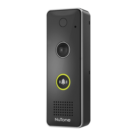
The doorbell camera should be in Discovery mode and the button indicator should flash
red and green. If the indicator does not flash, try pressing the call button for ten to
fifteen seconds to enter Discovery mode.
4 Follow Steps on App for Final Setup.
Doorbell Camera Troubleshooting
POWER
Q:The doorbell power cycles off and on?
A: Check that the doorbell camera power wires are
securely connected. The existing doorbell wiring may
be bad. Refer to Step 7.
Q: Why doesn’t the doorbell camera power up?
A: Refer to installation instructions:
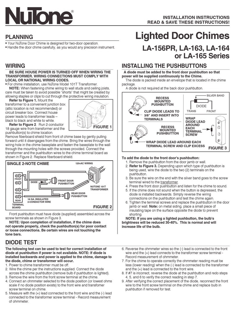
1. Confirm transformer power is turned ON.
2. Confirm diode is installed correctly.
3. Confirm wiring / connections are correct and secure.
TEST Doorbell Camera
Accessories for NuTone
DESCRIPTION
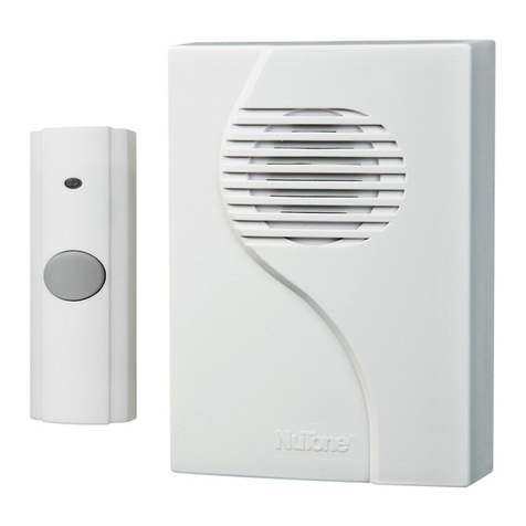
LA11WH Wired Door Chime
LA227WH Wi-Fi Door Chime
MODEL
NOTE: Remember to check App for
latest version of doorbell camera
firmware in the About Device Menu.
Wiring Doorbell without Chime Box connected (AC 16V, 10VA ~ 30VA)
1. Turn off the power.
2. Open the chime box.
3. Connect the two wires on
4. Turn on the power.
5. Blue LED flashes once.
6. The mechanical chime
will no longer ring. Add the optional Wi-Fi Chime if desired.
Doorbell
Connect the
two wires
on the
Transformer
terminal.
the Transformer terminal.
Transformer
REAR TRANS FRONT
If your transformer voltage is too low (see Step 10), proceed with Step 11.
Otherwise, skip Step 11 and proceed to Step 12.
The smart Doorbell Camera may be out of range of your Wi-Fi network. Move the
router or install a Wi-Fi extender. Note, the Doorbell Camera supports 2.4Ghz
networks only.
9 10
Status
Power ON
Flashing Blue once
Cold start at low temperatureFlashing Blue (Slow)
Connect to 16V transformer
without diode
Solid Blue 5 seconds 1. Occurs after power on, or push the button
2. Can’t ring the chime box
The voltage of transformer is low
Flashing Blue
5 seconds (fast)
1. Occurs after power on, or push the button
2. Proceed to Step 7.
Solid Blue Doorbell can’t work
LED Indicators Status
The voltage of transformer is too high
Note
Color
Solid Red Powering up
Flashing Green (Fast) Connecting to Cloud Server
Solid Green Connected to Cloud Server
Flashing Green (Slow)
Session in Progress
Flashing Red (Slow) Not connected to network
Flashing Red (Fast) Firmware update
Skip Step 7 and proceed to Step 8.
Flashing Green/Red Discovery Mode Skip Step 7 and proceed to Step 8.
11
12
• TURN power ON.
• Press doorbell button.
• If chime rings normally, continue to
next step.
• If chime DOES NOT ring
normally, the voltage of
transformer is low.
Go to Step 7. Or, replace with a
new 16 VAC, 30 VA transformer.
• Check the wire connections on
the unit, doorbell, and transformer.
Mounting Box/Hardware Pack
S97021209
S97021210 Camera Trim Ring
DCAM100RB Rough-in Box
View other home doors & windows made by Broan-NuTone on our website.
