3-EN
01GB04X208U-US_EN.fm
ALPINE X208U/INE-W977HD 68-34732Z04-A (EN)
EN
FR
ES
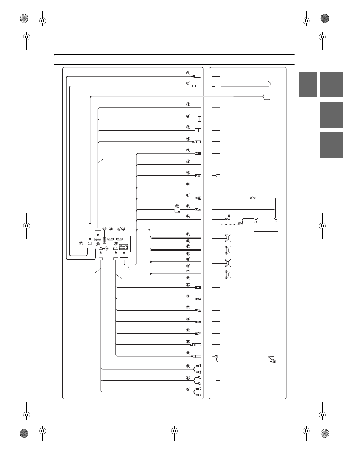
Precautions
• Be sure to disconnect the cable from the (–) battery post before
installing your unit. This will reduce any chance of damage to the
unit in case of a short-circuit.
• Be sure to connect the color coded leads according to the
diagram. Incorrect connections may cause the unit to
malfunction or damage to the vehicle’s electrical system.
• When making connections to the vehicle’s electrical system, be
aware of the factory installed components (e.g. on-board
computer). Do not tap into these leads to provide power for this
unit. When connecting the unit to the fuse box, make sure the
fuse for the intended circuit of the unit has the appropriate
amperage. When in doubt, consult your Alpine dealer.
• The unit uses female RCA-type jacks for connection to other
units (e.g. amplifier) having RCA connectors. You may need an
adaptor to connect other units. If so, please contact your
authorized Alpine dealer for assistance.
• Be sure to connect the speaker (–) leads to the speaker (–)
terminal. Never connect left and right channel speaker cables to
each other or to the vehicle body.
Accessory List
•X208U or INE-W977HD............................................................................... 1
•Power cable.................................................................................................... 1
•GPS Antenna.................................................................................................. 1
•Antenna mounting plate........................................................................... 1
•Cable clamp for antenna..................................................................... 1set
•USB extension cable....................................................................................1
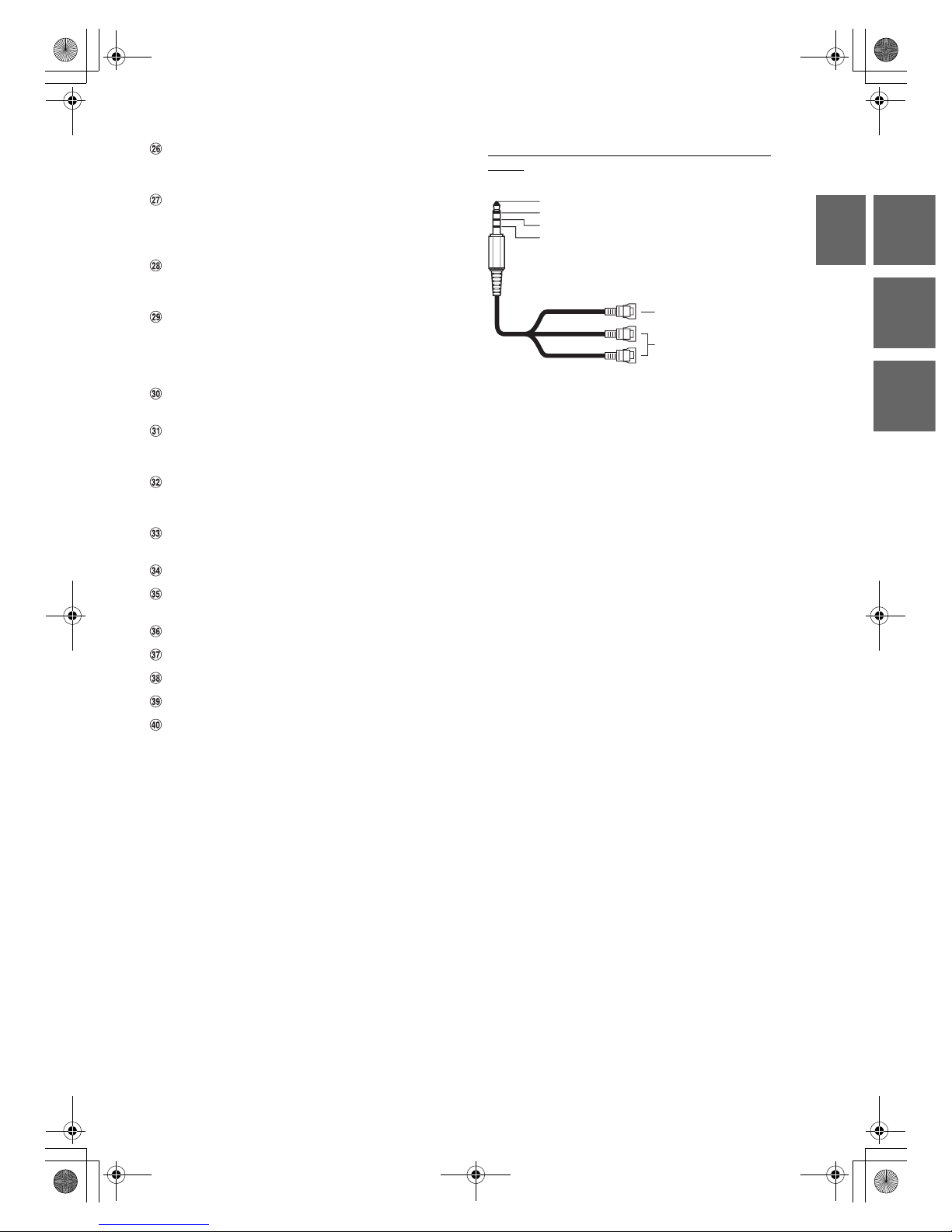
•PRE OUT cable ............................................................................................... 1
•Microphone.................................................................................................... 1
•Interface cable............................................................................................... 1
•W.REMOTE cable........................................................................................... 1
•Face plate (INE-W977HD only) ................................................................ 1
•HDMI Fixation Bracket................................................................................ 1
•Flush head screw (M5×8) .......................................................................... 4
•Screw (M5×8)................................................................................................. 4
•Owner’s Manual...................................................................................... 1set
Installation
Angle of installation
Install at an angle between horizontal and 30°. Note that installing at
an angle outside of this range will result in a loss of performance and
possibly damage.
1Clean the mounting location.
2Put on the GPS Antenna mounting plate.
3Mount the GPS Antenna.
• Do not mount the GPS Antenna inside the center console.
- Mount the GPS Antenna on a flat plane of the dash board or rear
tray.
- Make sure the GPS Antenna is not covered (obstructed) by any
metallic surface or object.
• If the GPS Antenna is mounted near the unit, the reception becomes
poor, and the location of your vehicle may not be displayed correctly.
- Mount the GPS Antenna far away enough from the unit.
- Bundle the GPS Antenna cable away from the rear of the unit.
• Some thermal reflection type or thermal absorption type glass may
interrupt high frequency waves. If reception is poor with the antenna
installed inside the car, try to mount the antenna outside the car.
For safe use, make sure of the following:
•Location is stable and firm.
•Driver’s view and operations are not obstructed.
•Microphone is located where the driver’s voice can be easily
picked up (for example, on the sun visor).
When you speak into the microphone, you should not have to change
your driving posture. This may cause a distraction, taking your
attention away from safely driving your vehicle. Carefully consider
direction and distance while mounting the microphone. Confirm that
the driver’s voice can be easily picked up at the selected location.
X208U user
To install the X208U, refer to the manual in the separately
purchased installation kit for each car type.
Caution
Do not block the unit’s fan, thus preventing air circulation. If
blocked, heat will accumulate inside the unit and may cause
a fire.
Air ventilation hole
Rear of the Unit
<example>
Caution concerning the installation location
Mounting the GPS Antenna inside the vehicle
Mounting the Microphone
0 - 30°
Antenna mounting plate
GPS Antenna
This unit
ML.book Page 3 Tuesday, November 29, 2016 10:45 AM