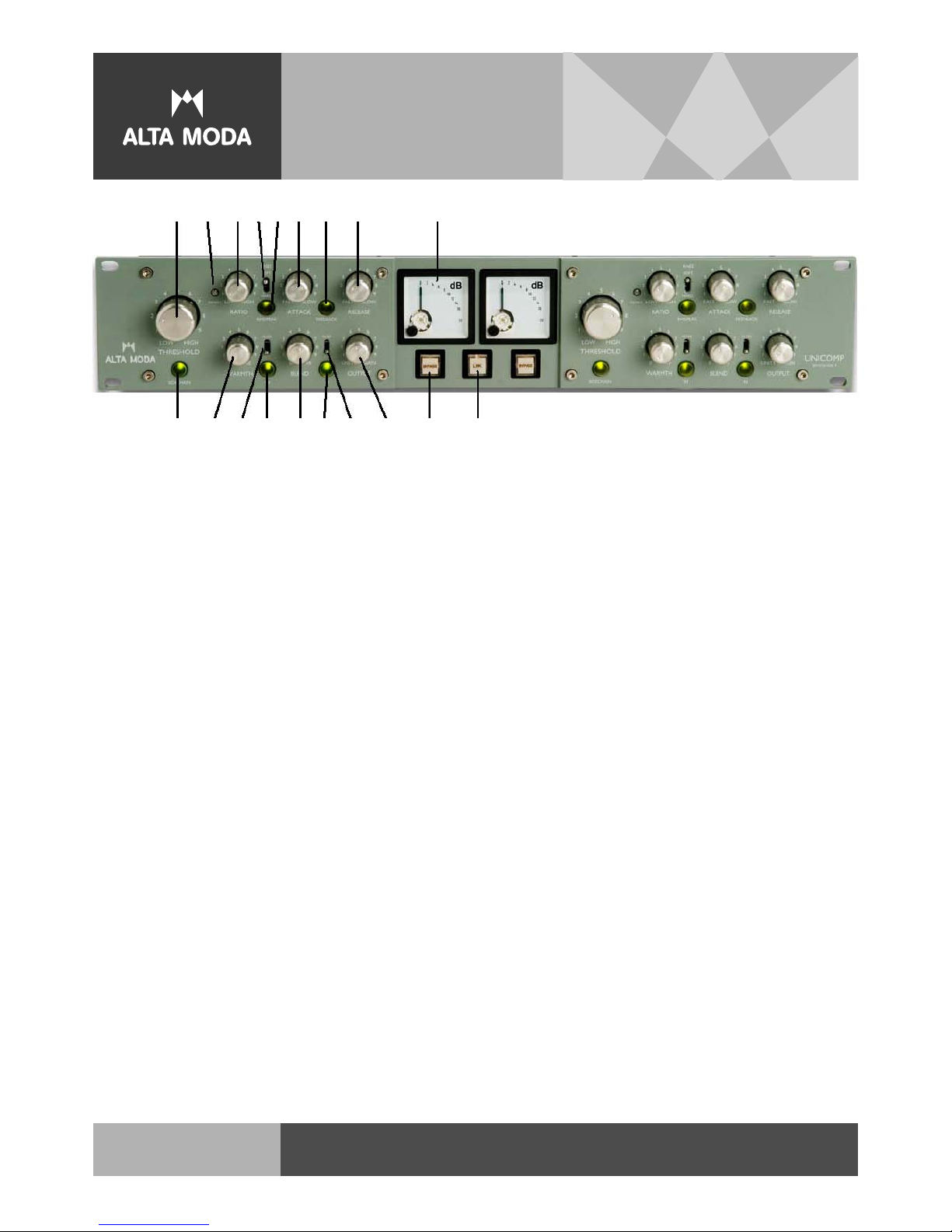
The Unicomp Control Functions
8. RELEASE – Affects how long the gain cell takes to return to unity
gain. Turning clockwise increases the amount of time the gain cell takes
to return to unity after compression occurs. This is a dynamic control
which is affected by other control settings and modes.
9. METER – Indicates gain reduction on a decibel scale. Analog meters
cannot accurately display peak responses, and typically indicate a lower
level of compression than is actually occurring, especially with more
percussive material.
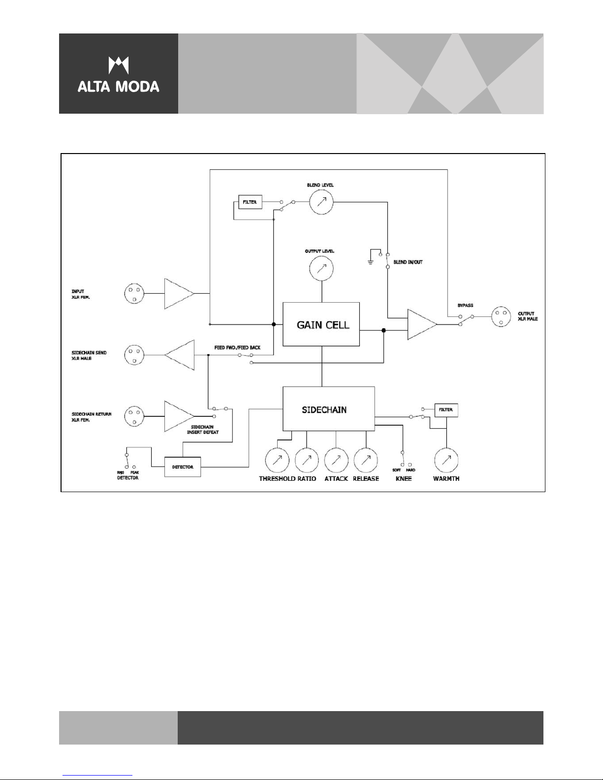
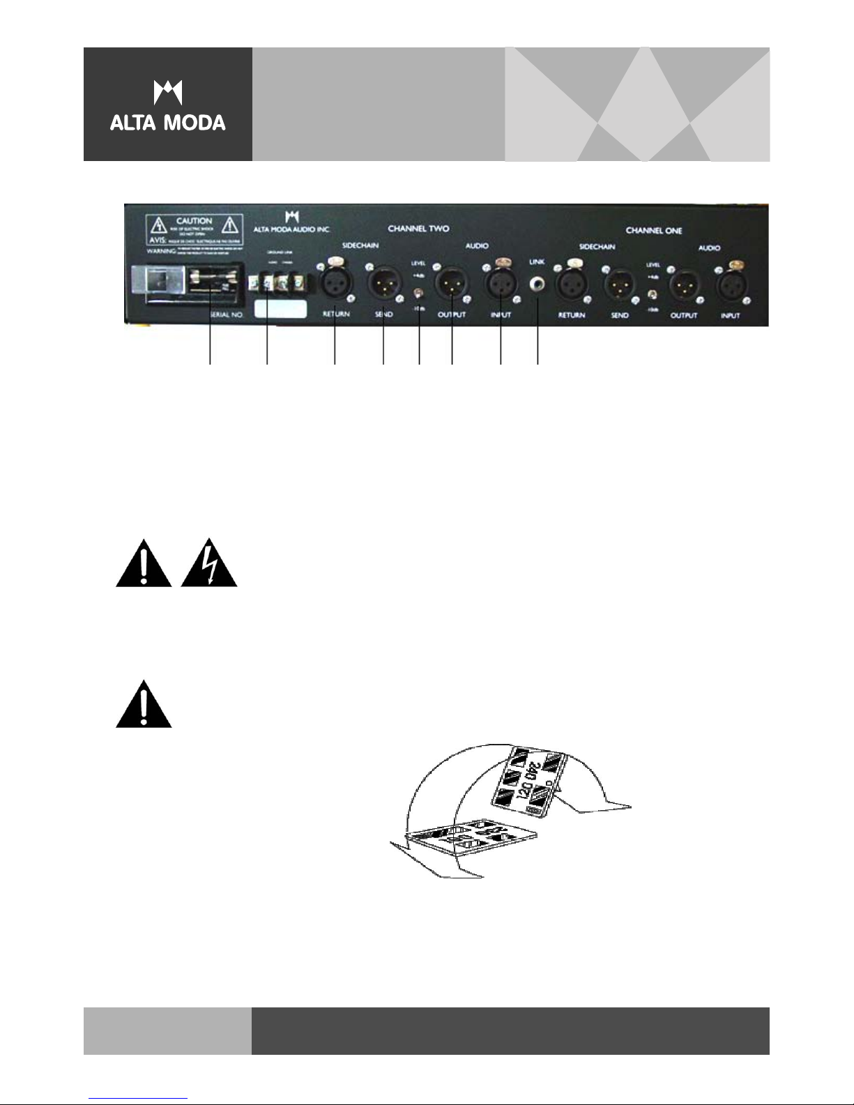
10. SIDECHAIN – This switch inserts a “signal loop” into the detector
path located on the back of the unit. This allows outboard processors
to effect how the compressor reacts to signal. Techniques for using
sidechain inserts are well covered in most practical recording
references and should be referred to.
11. WARMTH – Adds 2nd harmonic distortion to the gain cell. This
distortion is at a constant level, but increases relative to the
compressed signal; i.e. as compression increases, the ratio of distorted
signal-to-compressed signal increases.
12. FILTER (WARMTH) – In the “up” position, this switch rolls off the
low frequency response of the Warmth generator, so higher frequency
signals are less affected by lower frequency signal. The cut-off point
is approximately 1.5kHz.
13. IN (WARMTH) – Engages (illuminated) Warmth control.
14. BLEND – Mixes uncompressed (“dry”) input signal into the compressor
output with the compressed signal (“wet”). Clockwise rotation increases
the dry level from zero. As with the Warmth signal, the relative level
of “dry” to “wet” will increase as compression increases.
15. IN (BLEND) – Engages (illuminated) Blend control.
16. FILTER (BLEND) – When in the “up” position, a high-pass filter is
inserted into the BLEND signal path, mixing only higher frequency
material in with the compressed signal. The cut-off frequency is
approximately 650Hz.
17. OUTPUT – Boosts output level to compensate for lost overall signal
level while compressing. Signal level is unity when control is full
counterclockwise and increases when turned clockwise. The available
“makeup gain” is approximately 22dB.
18. BYPASS – This is a hard wire bypass. When engaged, effectively
removes the compressor from the signal path by rerouting the signal input
XLR jacks to the output XLR jacks.
19. LINK – Merges the outputs of the two detectors into a single signal
that feeds the left-side sidechain which controls both gain cells.
IMPORTANT: In link mode, the lower controls are still independent.
WARMTH, BLEND, AND OUTPUT controls still affect their respective
channels independently.
HIGH PERFORMANCEAUDIO
8