manuals.online logo
Brands
  1. Home
  2. •
  3. Brands
  4. •
  5. Altec Lansing
  6. •
  7. Amplifier
  8. •
  9. Altec Lansing 128B User manual

Altec Lansing 128B User manual

SPECIFICATIONS Figure 1
Type:
Gain:
Input Sensitivity:
Power Output:
Frequency Response:
Input Impedance:
Source Impedance:
Load Impedance:
Output Impedance:
Noise Level:
Power Amplifier
64 db
0.9 volt rms
40 watts at less than 2 THD,
30-20,000 cps
±1 db 3-30,000 cps
100,000 ohm potentiometer
150 and 600 ohms with 15095 Plug-In
Line Transformer
4 (12.6v.), 8 (18 V.), 16 (25 v.),
125 (70 v.) ohms ungrounded.
Less than 17% of nominal load
impedance.
85 db below rated output.
Controls: Front Panel — Volume Control,
Continuously variable composition,
Power and Meter Selection Switch
Chassis — Line Voltage Selection Switch
and High Pass Filter Switch, both
with locking plates
Power Supply: 105/125 volts, 50/60 cps, 125 watts
Tubes: 2 — 6CG7, 2 — 6CA7/EL34, 1 — 5AR4
Dimensions: 83/4" High, 19" Wide, 7" Deep
Color: Dark Green
Weight: 27 lbs.
Special Features: High Pass Filter for protection of
horn-loaded drivers
Power Transformer thermally protected
("Thermeguard") against overload or
high ambient temperatures.
DESCRIPTION
The 128B Altec Power Amplifier is a rack-mounted AC-operated power
amplifier designed for professional recording, sound reinforcing, and
all public address applications that require low distortion over a
wide frequency range. The 128B is the deluxe counterpart of the
popular 1568A and utilizes tube metering circuits, transformer thermal
protection ("Thermeguard"), and low residual distortion over a wide
frequency range. In addition to thermal protection, the power trans-
former is fitted with a heavy copper flux shield which reduces the
AC field, allowing operation in closer proximity to low-level equip-
ment without inducing hum that would otherwise be possible. Meter
illumination, over-temperature warning indicator, switch selected
power line setting, switch controlled high pass filter, plug-in line
transformer, and speaker impedance load taps as well as the 70
volt line connection are features of the 128B design.
METERING CIRCUITS
Each of the four amplifier tubes in the 128B can be checked for space
current by means of the front panel meter (Figure 1). The right-hand
selector switch on the front panel connects the meter to the appropri-
ate meter shunt in turn as indicated by the panel marking. Meter
indication within the green area is considered satisfactory. Output
tubes, V3 and V4, conduct more current when the amplifier is driven
to full output than they do in the idle condition. The meter shunts
for these stages have been selected so that the meter normally rests
at the 100% point in the absence of signal. Although normal pro-
gram material raises the average current flow only a small amount,
it would be possible with high-level sustained tones such as from
organ reproduction to cause the meter to be pegged if the switch is
left in the V3-V4 position. It is therefore recommended that the
normal rest position be at V1 or V2.
PROTECTIVE FEATURES
The power transformer of the 128B Amplifier is equipped with an
automatic re-setting thermal-type circuit breaker. This device is
located within the windings of the power transformer. It will sense
excessive rise of temperature due to tube malfunction, component
failure, excessively high ambient temperature due to inadequate
ventilation or the presence of other heat-producing apparatus. Should
the thermostat operate, the illuminated meter will darken and the
red over-temperature indicator directly above the meter will illumin-
ate (Figure 1). The amplifier will then automatically recycle into
operation as soon as safe temperatures have been re-established.
HIGH PASS FILTER
Horn-loaded driver loudspeakers are used in paging or voice rein-
forcing systems where excellent intelligibility is required in the
presence of high noise levels, the effects of wind and other disturb-
ances. This type of loudspeaker is limited in power handling capa-
bility below the cut-off frequency of the horn and must be protected
against excitation in this frequency range. The 128B Amplifier is
equipped with a two-section high-pass filter of the resistance capaci-
tance type. The "High Pass Filter" provides attenuation of approxi-
mately 8 db at 250 cps. The filter is inserted in the circuit by placing
the switch labeled "High Pass Filter" to the "In" position. The switch
is located on the chassis surface adjacent to vacuum tube V1 (Figure
2). To change the switch setting, remove the screw holding the lock-
ing plate so that the switch may be operated. The locking plate
should be re-assembled on the switch to prevent unauthorized or
inadvertent changing of the switch position. The locking plate is
used to hold the switch in either position by inverting the part as
required. The characteristic of the high-pass filter is shown on the
accompanying frequency response chart (Figure 4).
POWER LINE VOLTAGE SELECTOR
The 128B Power Amplifier is equipped with two line voltage taps
so that it may be operated at the most optimum setting in relation to
the supply line. Selection of the tap is by means of a switch labeled
"Line" located on the chassis surface adjacent to the power trans-
former (Figure 2). As shipped, the switch is in the 117 volt to 125
volt position and secured with a locking plate. Unless measurements
indicate conclusively that the power line voltage at the installation
runs below 117 volts, the line connection should not be changed. The
line switch is secured in the same manner as described in the high
pass filter paragraph. It is recommended that the apparatus always
be operated with the locking plate in place.
MECHANICAL INSTALLATION
The cabinet or other enclosure in which the 128B Amplifier is mounted
should have adequate provisions for air entry and exit. The amplifier
is constructed with a low top silhouette that provides a minimum of
impediment to the flow of air around the vacuum tubes and other
components. The shield which separates the power tubes from each
other and the power transformer is heated by radiation and in turn
provides a large area in the air stream with which to give up this
heat. When the amplifier is placed immediately above other heat-
producing apparatus, the ambient temperature of its immediate
environment is increased and can result in reduced component life.
Should this occur, and the thermal circuit breaker becomes operative,
provisions should be made to reduce the temperature in the general
area. This can be done by spacing the amplifier away from other heat-
producing apparatus by inserting the Altec 10399 13/4" perforated
panel above and below the 128B.
INPUT CONNECTIONS
Two pairs of input connections are provided on the 128B Amplifier
(Figure 2) Terminals 1 and 2, which connect directly to the input
potentiometer, are provided for unbalanced high impedance sources,
and to bridge unbalanced low impedance lines having signal voltage
of .9 or higher. Terminal 2 is grounded. Terminals 3 and 4 connect
to a standard octal socket into which an Altec 15095 line matching
transformer can be inserted. The 15095 transformer provides isolated
source impedances of 150 and 600 ohms and accommodates levels
up to +15 dbm. When the unit is shipped, the 600 ohm connection is
available at Terminals 3 and 4. Straps on the octal socket must be
changed in order to make use of the 150 ohm impedance. Strapping
information is shown on the schematic diagram (Figure 5).
OUTPUT CONNECTIONS
Connections for speakers of 4, 8, and 16 ohms are provided on the
output terminal strip (Figure 2). The 124 ohm tap provided is the
nominal 70 volt line connection. In matching speakers to the ampli-
fier, use the output tap which most nearly equals the speaker im-
pedance. If the load impedance falls between two output terminal
values, use the terminal of lower impedance.
70 volt line: The 70 volt distribution system permits connection of a
large number of speakers, each operating at a selected power level
without the necessity for computing load and amplifier impedances.
In this system, each speaker is equipped with a transformer (Altec
15000 series transformers) having a number of taps rated in terms
of power. The tap is selected which gives the power desired for the
individual speaker. The total of the power settings for all speakers
should be equal to, or less than, the amplifier power rating. The
128B Amplifier is equipped with outputs to drive either a 70 volt
line or a 25 volt line. The output windings are ungrounded and may,
therefore, be used to run balanced lines if required. Care should be
exercised in the wiring of the rack to isolate speaker lines from
input lines since they both appear on the same end of the amplifier.
TEST AND SERVICING
Should the amplifier become inoperative, it should first be deter-
mined that the power supply line is continuing to deliver current. If
the thermal breaker within the transformer has operated, the meter
illumination will have darkened and the red warning light on the
front panel (Figure 1) will be illuminated. Returning the amplifier
to normal temperature will correct this problem. If the meter is
illuminated but the amplifier fails to pass signal, the panel meter
may be used to determine which tube or stage has failed. Vacuum
tube V1 is a dual triode unit. If the first section of this tube becomes
inoperative, the meter placed in the V1 position will read full scale.
Should the second section of V1 fail, the meter will read zero. V2
is likewise a dual triode. Should only one section of this tube fail,
the meter will read about half scale. Should both sections fail, the
meter will read zero. In positions V3 and V4, zero meter indication
will result from an inoperative tube and full scale indication will
result from a tube having a shorted element. Failure of the meter
to indicate in any of the tube positions at the same time that the
meter is illuminated would indicate failure of the rectifier V5. In
conducting tests in order to determine conformance of the amplifier
to the performance specifications, the exact line voltage for the line
switch setting must be used. In the 117 to 125 volt position, the
exact line voltage is 125 volts, and in the 105 to 117 volt setting,
the exact line voltage is 117 volts.
Page 2
128B PARTS LIST
C1
.005 mfd ±20% Disc Erie Type 801
C2
.001 mfd ±10% Disc Erie Type 831
C3
.0022 mfd ±10% Disc Erie Type 801
C4
.5 mfd 400 v. Tubular Paper Pyramid Imp.
C5
47 mmf ±10% Disc Erie Type 831
C6A, 6B,
40-40 mfd 500 v. Mallory FP288-85° C.
11A, 11B
C7
20 mmf ±10% Disc Erie Type 831
C8, 9
.1 mfd 400 v. Tubular Paper-Micramold Tropicap
C10
100 mfd 50 v. Mallory WP 064-85° C.
J1
Tube Socket, Octal, Cinch 12543
M1
Meter, 0-200 Micro Amp. — Altec 5981
P1
Potentiometer 100K ±20% Type "J" A Taper
Dim. B 3/8", Dim. A 5/8" Plain Round Shaft
PL1, 2
Lamps—1847
PL3
Pilot Light Assembly — Eldema BG3-RC-S-2H-35K
R1
470,000 ohms ±10% 1/2 watt
R2
4700 ohms ±10% 1/2 watt
R3
1800 ohms ±1% 1/2 watt Deposited Carbon
R4
100,000 ohms ±10% 1.0 watt Deposited Carbon
R5, 7
68,000 ohms ±1% 1/2 watt Deposited Carbon
R6
113 ohms ±1% 1/2 watt Deposited Carbon
R8
2.2 M ohms ±10% 1/2 watt
R9
100,000 ohms ±10% 1/2 watt
R10
47,000 ohms ±10% 1.0 watt
R11
18,000 ohms ±10% 1.0 watt
R12
82,000 ohms ±1% 1/2 watt Deposited Carbon
R13, 21
10,000 ohms ±10% 1/2 watt
R14
27.4 ohms ±1% 1/2 watt, Deposited Carbon
R15, 16
47,000 ohms ±1% 1.0 watt Deposited Carbon
R17, 18
220,000 ohms ±10% 1/2 watt
R19, 20
100 ohms ±10% 1/2 watt
R22, 23
3.3 ohms ±3% 1.0 watt — Dalohm RLS-1A
R24
600 ohms ±5% 3 watt, Ohmite Axial Lead
R25
4700 ohms ±10% 1.0 watt
R26
50 ohms ±10% 10 watt, (RW20G500,
Commercial Grade)
S1
Slide Switch, Stackpole SS-50
S2
Slide Switch, Stackpole SS-36-1
S3
AC & Meter Switch — Altec 13717
SR1
Silicon Rectifier-Altec 13871
T1
Output Transformer — Altec 16615
T2
Power Transformer — Altec 6716
V1, 2
6CG7, Vacuum Tube (RCA)
V3, 4
6CA7/EL34 Vacuum Tube (Amperex, Mullard)
V5
5AR4 Vacuum Tube (GE, Amperex)
Page 3

Other Altec Lansing Amplifier manuals

Altec Lansing 9446A POWER AMPLIFIER User manual

Altec Lansing

Altec Lansing 9446A POWER AMPLIFIER User manual

Altec Lansing 1407A POWER AMPLIFIER User manual

Altec Lansing

Altec Lansing 1407A POWER AMPLIFIER User manual

Altec Lansing 4200A POWER AMPLIFIER User manual

Altec Lansing

Altec Lansing 4200A POWER AMPLIFIER User manual

Altec Lansing 1707C MIXER AMPLIFIER Training manual

Altec Lansing

Altec Lansing 1707C MIXER AMPLIFIER Training manual

Altec Lansing 1590E User manual

Altec Lansing

Altec Lansing 1590E User manual

Altec Lansing 9440A POWER AMPLIFIER User manual

Altec Lansing

Altec Lansing 9440A POWER AMPLIFIER User manual

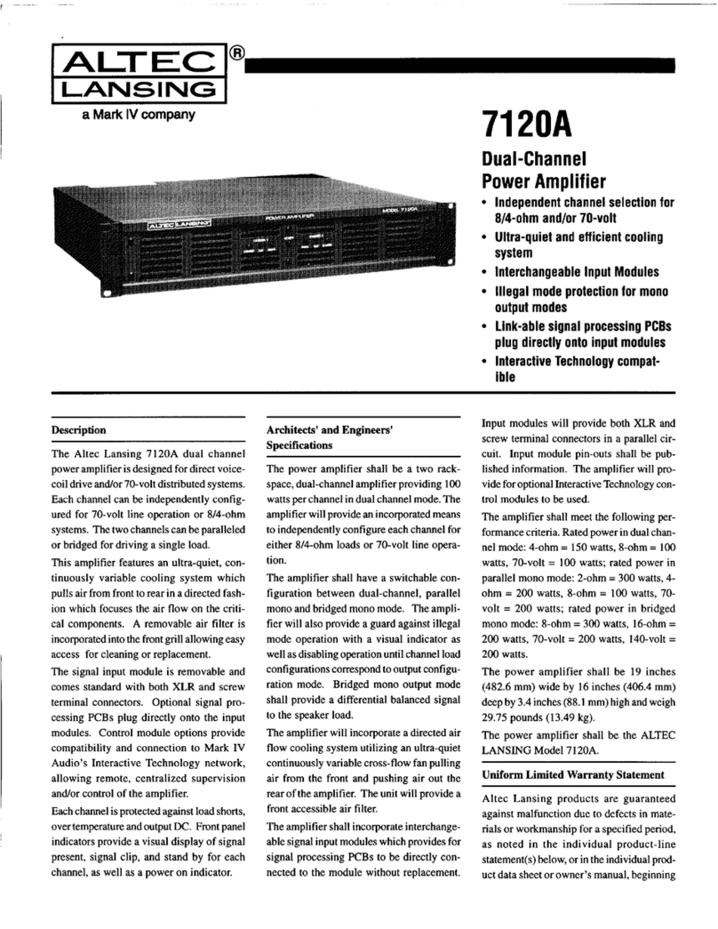
Altec Lansing 7120A POWER AMPLIFIER User manual

Altec Lansing

Altec Lansing 7120A POWER AMPLIFIER User manual

Altec Lansing 612 SPEAKER CABINET PLAN User manual

Altec Lansing

Altec Lansing 612 SPEAKER CABINET PLAN User manual

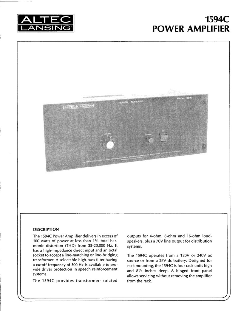
Altec Lansing 1594C POWER AMPLIFIER User manual

Altec Lansing

Altec Lansing 1594C POWER AMPLIFIER User manual

Altec Lansing 9444B POWER AMPLIFIER SERVICE Training manual

Altec Lansing

Altec Lansing 9444B POWER AMPLIFIER SERVICE Training manual

Altec Lansing 9446A POWER AMPLIFIER User manual

Altec Lansing

Altec Lansing 9446A POWER AMPLIFIER User manual

Altec Lansing 1268 POWER AMPLIFIER User manual

Altec Lansing

Altec Lansing 1268 POWER AMPLIFIER User manual

Altec Lansing 9444B POWER AMPLIFIER SERVICE User manual

Altec Lansing

Altec Lansing 9444B POWER AMPLIFIER SERVICE User manual

Altec Lansing 9475A User manual

Altec Lansing

Altec Lansing 9475A User manual

Altec Lansing 9442ASA Anniversary Series Operating instructions

Altec Lansing

Altec Lansing 9442ASA Anniversary Series Operating instructions

Altec Lansing 1594C POWER AMPLIFIER User manual

Altec Lansing

Altec Lansing 1594C POWER AMPLIFIER User manual

Altec Lansing 260A OI User manual

Altec Lansing

Altec Lansing 260A OI User manual

Altec Lansing 1588C SIGNAL PROCESSING User manual

Altec Lansing

Altec Lansing 1588C SIGNAL PROCESSING User manual

Altec Lansing 2280B POWER AMPLIFIER User manual

Altec Lansing

Altec Lansing 2280B POWER AMPLIFIER User manual

Altec Lansing 9446A POWER AMPLIFIER SERVICE User manual

Altec Lansing

Altec Lansing 9446A POWER AMPLIFIER SERVICE User manual

Altec Lansing 6125A User manual

Altec Lansing

Altec Lansing 6125A User manual

Altec Lansing 1594C POWER AMPLIFIER User manual

Altec Lansing

Altec Lansing 1594C POWER AMPLIFIER User manual

Altec Lansing 1707C MIXER AMPLIFIER User manual

Altec Lansing

Altec Lansing 1707C MIXER AMPLIFIER User manual

Altec Lansing 9473A User manual

Altec Lansing

Altec Lansing 9473A User manual

Popular Amplifier manuals by other brands

Fender Acoustasonic 30 operating instructions

Fender

Fender Acoustasonic 30 operating instructions

DAPAudio PA-805CDTU user manual

DAPAudio

DAPAudio PA-805CDTU user manual

AMT S-Drive FX-Drive Series user manual

AMT

AMT S-Drive FX-Drive Series user manual

Lab.gruppen FP+ Series FP 10000Q Technical data

Lab.gruppen

Lab.gruppen FP+ Series FP 10000Q Technical data

Alpine 3558 owner's manual

Alpine

Alpine 3558 owner's manual

Denon POA-2200 Service manual

Denon

Denon POA-2200 Service manual

Evh 5150III 50S 6L6 user manual

Evh

Evh 5150III 50S 6L6 user manual

SolidView SN-614 user manual

SolidView

SolidView SN-614 user manual

Marshall Amplification DSL100HR Service manual

Marshall Amplification

Marshall Amplification DSL100HR Service manual

Citronic 171.231 – MA800 user manual

Citronic

Citronic 171.231 – MA800 user manual

Taurus T-450 operating manual

Taurus

Taurus T-450 operating manual

RS100 PA-4040 instructions

RS100

RS100 PA-4040 instructions

Harman Crown CTs Series Operation manual

Harman

Harman Crown CTs Series Operation manual

Kemo Electronic M040N quick guide

Kemo Electronic

Kemo Electronic M040N quick guide

Two Notes VM-202 user manual

Two Notes

Two Notes VM-202 user manual

Koss EQP1 instructions

Koss

Koss EQP1 instructions

Monacor PA-1206 instruction manual

Monacor

Monacor PA-1206 instruction manual

Omron E3NC-LA0 instruction sheet

Omron

Omron E3NC-LA0 instruction sheet

manuals.online logo
manuals.online logoBrands
  • About & Mission
  • Contact us
  • Privacy Policy
  • Terms and Conditions

Copyright 2025 Manuals.Online. All Rights Reserved.