Owners Information
As the owner of a EAGLESUN™ solar water heater there are some questions you may have about the system and
how it operates. Your solar water heater model is commonly referred to as a roof mounted, open loop, close coupled,
Thermosiphon system and is one of the most efficient solar water heater types available worldwide.
What is a Thermosiphon System?
A Thermosiphon system is a system where the heated water in the solar collectors rises up into the storage tank by
natural Thermosiphon action. Thermosiphon action occurs when water which is heated in the collectors expands
becoming lighter allowing colder heavier water to fall by gravitational force to the bottom of the collector. The cold
water falling to the bottom of the collector pushes the hotter lighter water back up into the storage tank. This natural
action commonly known as Thermosiphon action occurs without any moving parts or auxiliary electrical energy input
to the system
What is a Close Coupled System?
A close coupled system is one where the household hot water storage tank and solar collectors are both mounted on
the roof. Typically the tank is above but in close proximity to the collectors. The tank and collectors are connected
together with ¾” copper tube, which is used to transfer heated water from the collectors to the storage tank.
What is an Open Loop System?
An Open Loop System is a system where the water used in the household (hot water) circulates through the solar
collector panels transferring solar energy into the storage tank. This system type is used in locations where the
ambient temperature never falls below freezing point (32°F) and where the water quality is good – less than 600 ppm
Total Dissolved Solids (TDS).
What is a Closed Loop System?
A Closed Loop System is a system where two water loops are contained within the solar water heater. The first loop
is the household water storage tank which stores the heated household water used within the household. The
second loop is the solar collector loop which is fully sealed and mechanically separated from the household water
loop by a heat exchanger system. The fluid within the solar collector loop is a mixture of household water and food
grade propylene glycol. This fluid mix transfers solar energy from the solar collectors to the heat exchanger system
and prevents damage to the solar collectors should the ambient temperature fall below freezing point. This system
type can be used in any climatic location and with any water quality considered suitable for human consumption
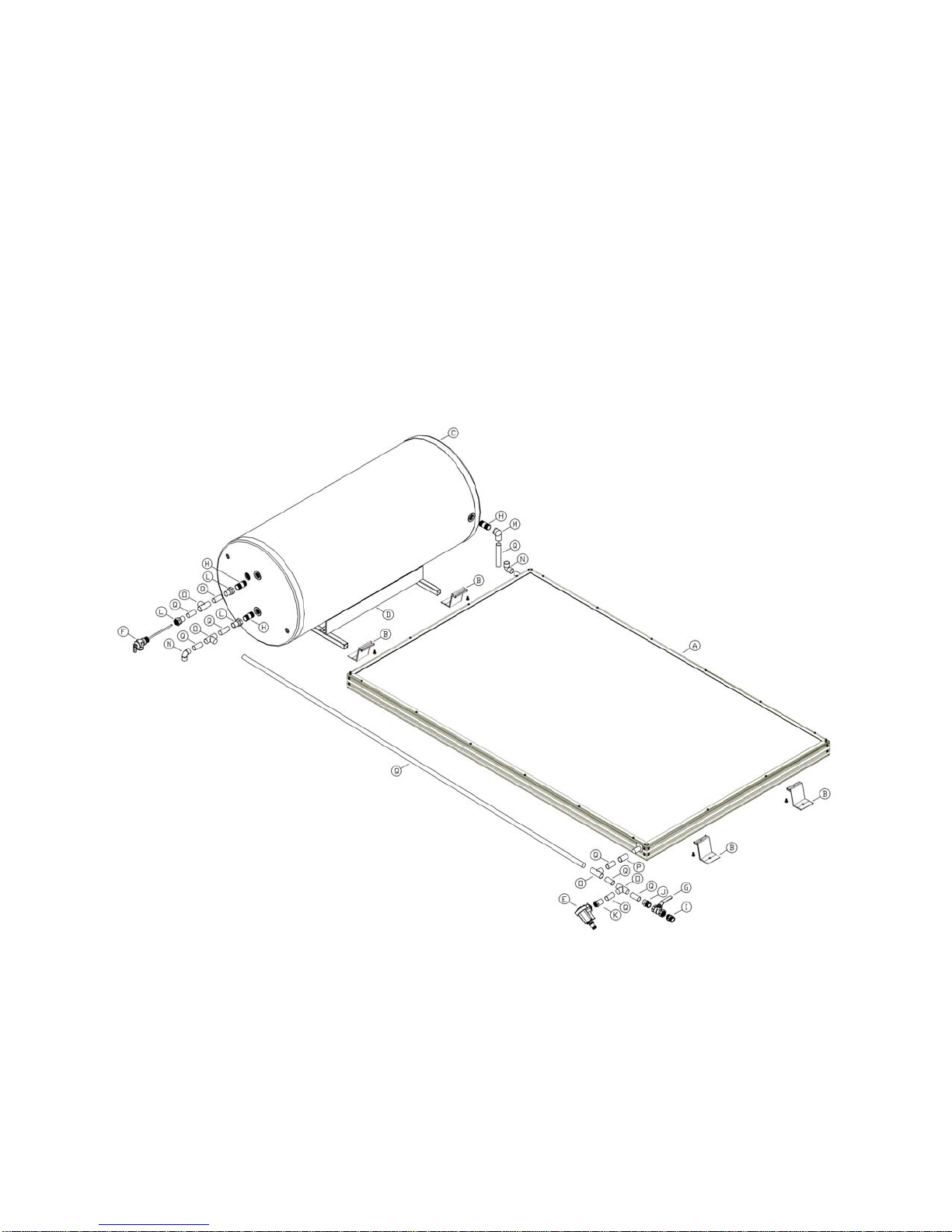
How does my system work?
The three main components of your solar water heater system are the potable water storage tank, the solar collector
(s) and Ancillary Energy Support (AES) System. The AES system can be either electric or gas operated dependant
on the model purchased.
The potable water storage tank is used to store the heated water ready for household use. It is constructed using high
quality stainless steel to provide long life and is insulated with a high density polyurethane material to ensure minimal
heat losses and maximized structural strength. The solar collectors contain a multi-tube copper water way system
welded to a solar absorber plate, the combination of which collects solar energy and transfers it to the fluid within the
collector loop. The absorber plate system is enclosed in an insulated metal casing covered with a high strength
tempered glass sheet that protects the absorber system from physical damage.
An electric Ancillary Energy Support (AES) system uses and electric element to heat part of the stored household
water on those occasions when there is reduced solar energy available. (e.g. cloudy days). The electric element is
thermostatically controlled so it only delivers the top up energy required then turns off automatically. A Gas AES
system uses a remotely mounted gas continuous flow water heater connected in series with the hot water supply line
to your house hot water pipe work. As the hot water from the solar storage tank passes through the gas heater its
temperature is automatically monitored. If the temperature is below 120°F the gas heater will add the degrees
required to deliver hot water of at least 120°F. If the water temperature is above 120°F the gas heater will not decide
not to ignite.
Under normal operating conditions the potable water within the storage tank is heated by the solar collectors. In an
Open Loop System where the household hot water is in the collector loop, cold water is pushed downwards, via the
long external pipe from the storage tank to the bottom of the solar collector. As the water is heated in the absorber by
the sun, it rises to the top of the collector then travels through the short external pipe into the storage tank.
3


 Operation and maintenance instructions")