Altinex TNP327 User manual

TNP327 INTERCONNECT BOX User’s Guide
400-0704-004
1
Welcome!
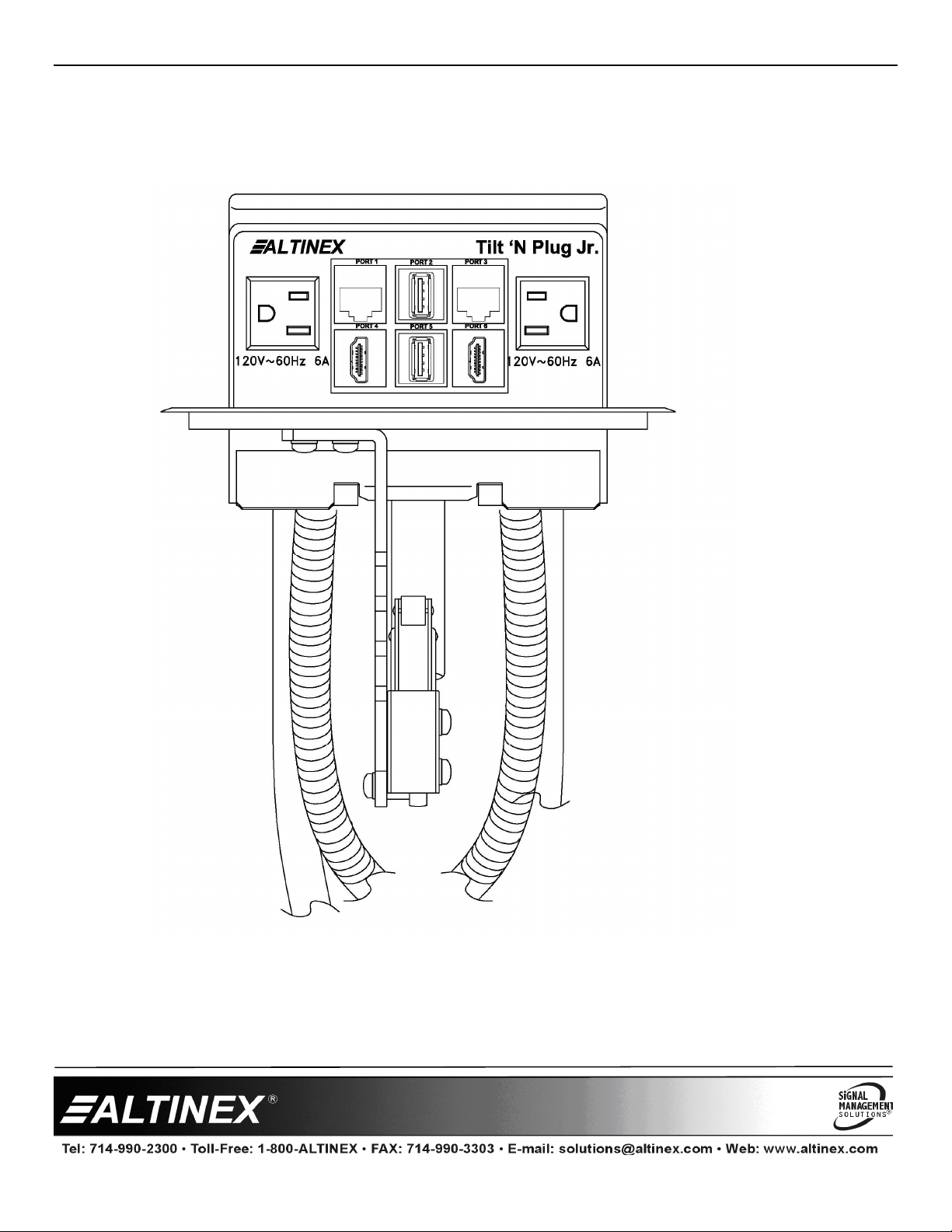
We greatly appreciate your purchase of your TNP327 Series
Tilt 'N Plug. We are sure you will find it reliable and simple to
use. Superior performance for the right price, backed by solid
technical and customer support is what Altinex offers.
We are committed to providing Signal Management Solutions®
to our customers for the most demanding audiovisual
installations at competitive pricing and we welcome you to join
the ranks of our many satisfied customers throughout the world.
1. Precautions and Safety Warnings
Please read this manual carefully before using your Tilt 'N Plug
Interconnect Box. Keep this manual handy for future reference.
These safety instructions are to ensure the long life of your
Tilt 'N Plug. and to prevent fire and shock hazards. Please read
them carefully and heed all warnings.
1.1 General
•Unauthorized personnel shall not open the unit as there
are high-voltage components inside. Qualified Altinex
service personnel or their authorized representatives
must perform all service.
1.2 Installation Precautions
•For best results, place the Tilt 'N Plug in a dry area away
from dust.
•To prevent fire or shock, do not expose this unit to water
or moisture. Do not place the unit in direct sunlight, near
heaters or heat-radiating appliances, or near any liquid.
Exposure to direct sunlight, smoke, or steam can harm
internal components.
•Handle carefully; dropping or jarring can cause damage.
•Never place fingers inside the opening on either side of
the unit; this could cause injury due to sharp edges.
•Do not place heavy objects on top of the TNP. Do not
use excessive force to push down on the top of the unit.
•Disconnect the power cord to turn off the power. This
supplies power to the socket on the pop-up panel. The
power outlet should be installed near the equipment and
be easily accessible.
•We recommend using wall outlets with a Ground Fault
Circuit Interrupter (GFCI) for maximum protection.
•Install cables according to the instructions found herein.
Do not force or pull any cables attached to the TNP.
1.3 Cleaning
•Surfaces should be cleaned with a dry cloth. Never use
strong detergents or solvents such as alcohol or thinner.
Do not use a wet cloth or water to clean the unit.
2. Installation Procedures
Step 1 Cut an opening into the table’s surface. Refer to the Altinex website at www.altinex.com
for table cutout requirements.
NOTE The table can be 2.25 in (57 mm) or less in thickness. Always confirm dimensions
before cutting to insure that specifications have not changed.
Step 2. Insert the TNP327 into the table cutout.
Step 3. Place the support brackets under the table and place them between the support mount
grooves on the side of the unit. Attach the brackets to the groove at the desired height
and secure them to the bottom of the table using the knurled table securing screws
provided with the additional wing nuts for added tightening. See Diagram 3 for details.
Step 4. To lower the unit, push on the top cover until it locks into place.
Step 5. Secure all cables to the underside of the table using the cable clamps and screws
included with the TNP. Pass the power cord from the bottom of the housing and attach it
to the table separate from the signal cables. Leave enough slack in the service loop to
allow for easy opening and closing, but not too much as to cause excess drooping of the service loop.
Step 6. Connect the appropriate cables with the correct input connectors on the bottom of the unit.
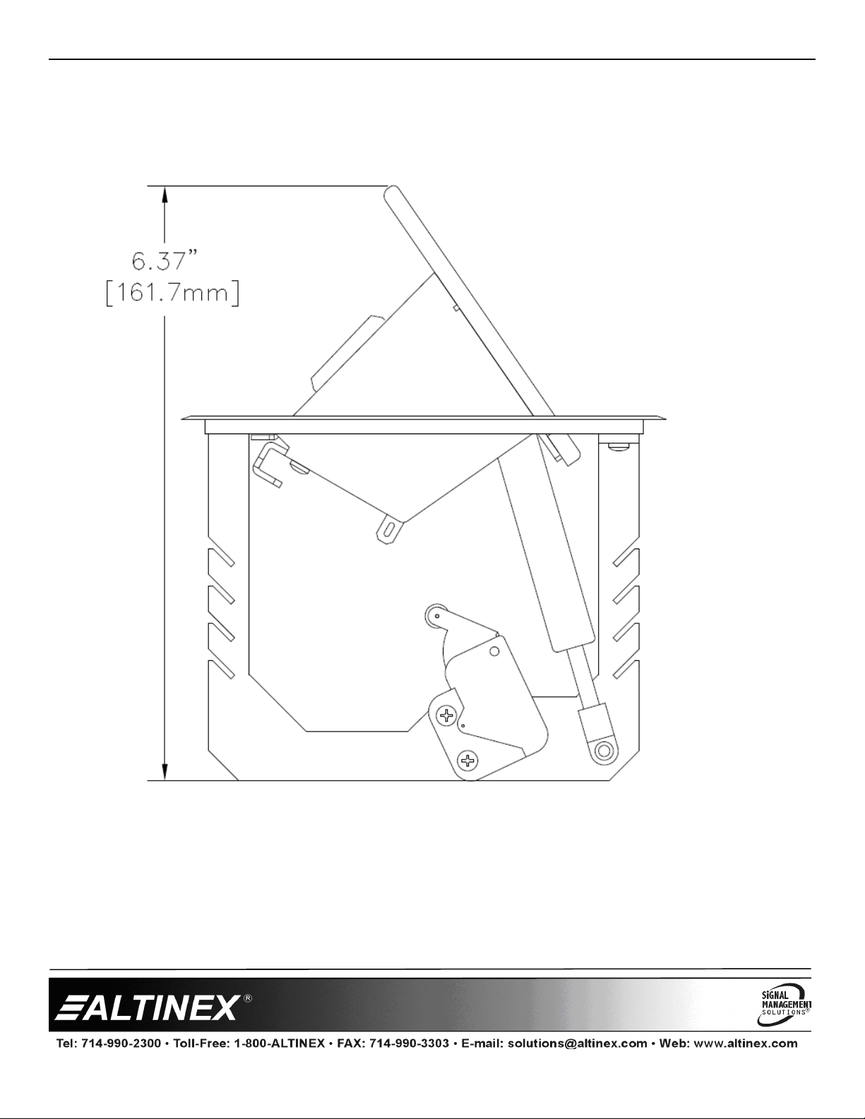
Step 7. Once you have applied power and connected the proper cables on the bottom of the unit you may raise the unit. To raise the
unit into position, push down on the front of the top cover; the latching mechanism will then release, allowing the pneumatic
spring to raise it into position.
Note It may be necessary to adjust the service loop of the cables for optimal performance.
3.
Limited
Warranty/Return Policies
Please see the Altinex website at www.altinex.com for details on warranty and return policies.

TNP327 User’s Guide
400-0704-004
2
4. Technical Specification
Specifications are subject to change. Please visit http://www.altinex.com for up-to-date specification
Features/Description TNP327/327C*
Pass-Through AC Power 9ft. (3.0 m)
120 VAC,60 Hz, 12A NEMA Socket-Plug
Agency Approval
UL/C-UL Listed File E254082
Audio, Video,
Communication 6 ft. (2 m)
HDMI **HDMI F-M (2)
Network CAT-6 (RJ-45) F-M (2)
USB USB Type A F-M (2)
Accessories Included
Hardware -Mounting screws/brackets
-Cable clamps/screws
Table 1 TNP327 General Specifications
Mechanical TNP327
Max. Table Thickness 2.25 in (57 mm)
Height, opened 6.4 in (163 mm)
Width 5.7 in (145 mm)
Depth 5.2 in (132 mm)
Finish Standard:
Models ending in S:
Matte Black
Brushed Aluminum
Weight (approx.) 2.75 lb. (1.25 kg)
Shipping Weight 5.5 lb. (2.5 kg)
T°Operating 10°C - 35°C
T°Maximum 40°C
Humidity 90%non-condensing
Table 2 TNP327 Mechanical Specifications ***
Electrical
(Dual Outlet Panel)
TNP327
Power Rating
(pass-through AC power)
120VAC,60Hz,
Up to 12A total
Table 3 TNP327 Electrical Specifications ***
* Models ending in “C” are customizable.
Model ending in ”S” have brushed aluminum finish .
** HDMI, the HDMI Logo, and High-Definition Multimedia Interface are trademarks or registered trademarks of HDMI Licensing LLC
in the United States and other countries.
*** Dimensions and ratings include the customizable “C” models and “S” models .

TNP327 User’s Guide
400-0704-004
3
5. The TNP327 Interconnect Box
•Available in high quality matte black finish or clear brushed finish
•Pre-configured, compact hybrid interconnect solution with HDMI USB
and Network interconnects or factory configured as a TNP327
•Dual AC sockets rated for up to 12A from one power cord
•Simple, drop-in installation
•Gas spring for smooth operation
•UL listed
The TNP327 is a compact interconnect solution designed for mounting into tables, podiums, or other furniture as part of a presentation
system. Inputs are accessed by pushing down on the top cover allowing the unit to tilt open. The inputs are hidden by pressing down on
the top cover until the latching mechanism engages.
In the closed position, the top cover lays almost flush with the tabletop. This tabletop solution offers up to 12 Amps from the AC sockets
plus two HDMI, two USB and two network pass-through cables. The passive cables are 6 ft. and are bundled together for organized
cable management. The power cable is split to deliver power to both outlets on the tabletop from one AC plug.
The TNP327 is one of many solutions available in the TNP Jr. product line that can be customized with many different connectivity
options as a TNP327C.

TNP327 User’s Guide
400-0704-004
4
6. Application Diagrams
Diagram 1: Typical Setup and use of a TNP327

TNP327 User’s Guide
400-0704-004
5
Diagram 2: Front View

TNP327 User’s Guide
400-0704-004
6
Diagram 3: Mounting the TNP327

TNP327 User’s Guide
400-0704-004
7
Diagram 4: Side Dimensions

TNP327 User’s Guide
400-0704-004
8
Diagram 5: Top Bezel Dimensions

TNP327 User’s Guide
400-0704-004
9
7. Operation
7.1 Opening and Closing the Tilt 'N Plug
The Tilt 'N Plug will open easily when the top is pressed down
and then released.
When the Tilt 'N Plug is not in use, simply press the top down
until it is level with the surface of the table and then release. The
unit will remain hidden until needed again.
7.2 Power/Signal Connections
Connect external devices to the appropriate connector on the
Tilt 'N Plug. Remember, the devices plugged into the AC power
connectors should not draw more than 12A total.
8. Troubleshooting Guide
The Tilt 'N Plug supplied was carefully tested and no problems were detected. However, we would like to offer the following
suggestions:
TNP
Symptom Resolution
Signal quality is poor.
1. Please make sure that the highest quality video and network cables are used.
2. The TNP is a passive unit and does not alter signals in any way. If there is suspected problem
with the signal quality, check the quality of the cables coming into and the TNP and connecting
to the output of the TNP. If they are of low quality or improperly assembled, this will affect the
overall quality of the signal.
Damaged power cord 1. Make sure that no cable or power cord is damaged or pinched.
2. If there has been damage, do not use the Tilt 'N Plug. Please call the Altinex Customer Service
Department at (714) 990-2300 to have the unit repaired.
Unit raises too slowly 1. If the unit does not rise into position correctly, check the service loops for the signal and power
cords on the bottom of the unit. If the service loop is too small the cables will counteract the
spring trying to raise the unit into position.
Unit tilts up too fast 1. If the unit rises into position too fast, check the service loops for the signal and power cords on
the bottom of the unit. If the service loop is too large and the cables are putting upward pressure
on the unit, the unit will tilt up too fast.
Unit does not close all
the way
1. If the unit does not close flush with the bezel, check the service loops for the signal and power
cords on the bottom of the unit. If the service loop is putting upward pressure in the unit, the unit
will not be able to seat all the way down.
This manual suits for next models
3
Table of contents
Other Altinex Conference System manuals
Popular Conference System manuals by other brands

AT&T
AT&T MERLIN LEGEND Release 2.0 Analog Multiline... Equipment and operations guide

Zenitel
Zenitel Phontech ICS 6200 installation manual

Yealink
Yealink MTouch Plus quick start guide

Zycoo
Zycoo Ei Series user guide

Yealink
Yealink MVC940 quick start guide

Televic
Televic D-CERNO Installation and user manual