Altinex PNP515 User manual

PNP515
PNP515 PNP515
PNP515
Series
SeriesSeries
Series
Customizable Pop
Customizable PopCustomizable Pop
Customizable Pop
‘N Plug
‘N Plug‘N Plug
‘N Plug
®
with Custom Tabletop
with Custom Tabletopwith Custom Tabletop
with Custom Tabletop
Surface
SurfaceSurface
Surface
User’s Guide
400-0464-005
1
Welcome!
e greatly appreciate your purchase of the PNP515/517/527/537/547
Customizable Pop ‘N Plug (PNP) with Custom Tabletop Surface. e are sure
you will find it reliable and simple to use. Superior performance for the right
price, backed by solid technical and customer support is what ALTINEX has to
offer.
e are committed to providing our customers with Signal Management
Solutions
®
to the most demanding audiovisual installations at competitive
pricing and we welcome you to join the ranks of our many satisfied customers
throughout the world.
1. Precautions and Safety Warnings
Please read this manual carefully before using your PNP Interconnect Box.
Keep this manual handy for future reference. These safety instructions are to
ensure the long life of your PNP and to prevent fire and shock hazards. Please
read them carefully and heed all warnings.
1.1 General
•Qualified ALTINEX service personnel or their authorized representatives
must perform all service.
•Unauthorized personnel shall not open the unit since there are
high-voltage components inside
1.2 Installation Precautions
•For best results, place the PNP in a dry area away from dust and
moisture.
•To prevent fire or shock, do not expose this unit to water or moisture.
Do not place the PNP in direct sunlight, near heaters or heat-radiating
appliances, or near any liquid. Exposure to direct sunlight, smoke, or
steam can harm internal components.
•Handle the unit carefully. Dropping or jarring can cause damage.
•Never place fingers inside the openings of the unit. This action could
cause serious injury due to sharp edges inside the unit.
•Do not place heavy objects on top of the PNP. Do not use excessive force
to push down on the top of the unit.
•To turn off the main power, disconnect the power cord. The power
outlet should be near the equipment and easily accessible.
•ALTINEX recommends using wall outlets with a Ground Fault Circuit
Interrupter (GFCI) for maximum protection.
•Install all cables according to the instructions. Do not force or pull any
cable or power cord attached to the PNP.
1.3 Cleaning
•Surfaces should be cleaned with a dry cloth. Never use strong detergents
or solvents such as alcohol or thinner. Do not use a wet cloth or water to
clean the unit.
1.4 FCC Notice
•This device complies with Part 15 of the FCC Rules. Operation is subject
to the following two conditions: (1) This device may not cause harmful
interference, and (2) this device must accept any interference received,
including interference that may cause undesired operation.
•This equipment has been tested and found to comply with the limits for
a Class A digital device, pursuant to Part 15 of the FCC Rules. These
limits are designed to provide reasonable protection against harmful
interference when the equipment is operated in a commercial
environment. This equipment generates, uses, and can radiate radio
frequency energy and, if not installed and used in accordance with the
instructions found herein, may cause harmful interference to radio
communications. Operation of this equipment in a residential area is
likely to cause harmful interference in which case the user will be
required to correct the interference at his own expense.
•Any changes or modifications to the unit not expressly approved by
ALTINEX, Inc. could void the user’s authority to operate the equipment.
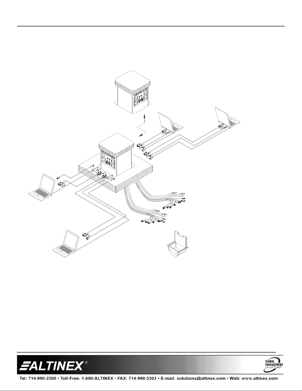
2. Installation Procedures
Step 1. Refer to the ALTINEX website, www.altinex.com, to download the latest templates and instructions for tabletop cutting requirements and installation
instructions.
In order to do this, locate the PNP on the website and go to its detail page. The links to the templates, user’s guide, and more are on the left hand side
of the screen.
Step 2. Print all information applicable to the installation of the PNP, including the templates and any detailed installation instructions.
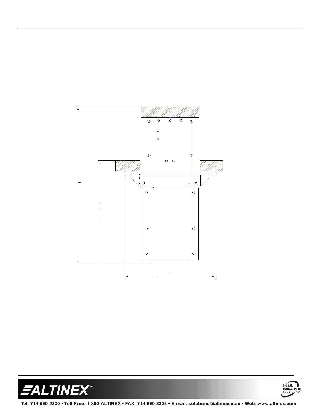
Step 3. Cut an opening into the table’s surface. The cutout is the top of the PNP, so it must be cleanly cut and saved. This operation should be performed by
experienced professionals in order to insure accuracy and to be aesthetically pleasing.
Note: Always confirm dimensions before cutting to insure that specifications have not changed.
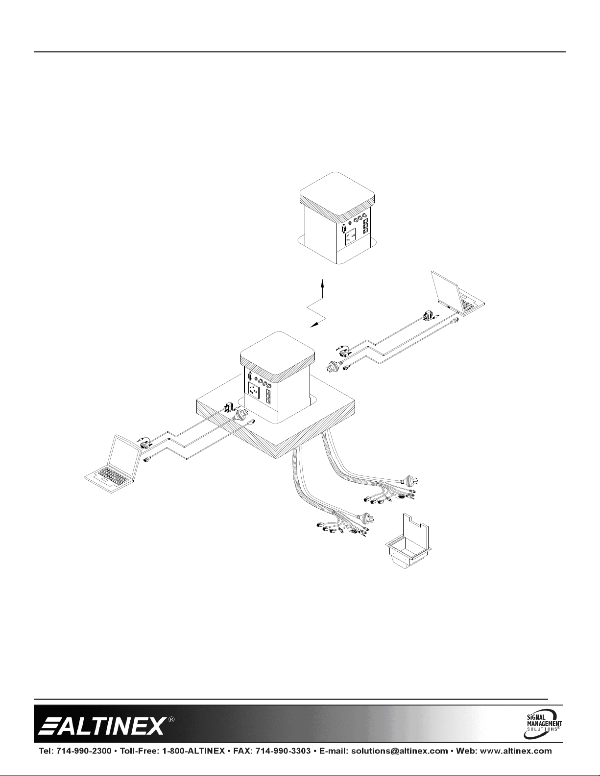
Step 4. Install the PNP into the table per the installation instructions provided on the website.
Step 5. Connect all cables to their appropriate sources and/or destinations. The PNP is now ready for operation.
3. Limited Warranty/Return Policies
Please see the ALTINEX website at www.altinex.com for details on warranty and return policies.

PNP515/517/527/537/547
PNP515/517/527/537/547PNP515/517/527/537/547
PNP515/517/527/537/547
User’s Guide
400-0464-005
2
4. Technical Specifications
Specifications are subject to change. See www.altinex.com for up-to-date information.
Features/Description PNP
Inputs (F) / Outputs (M) PNP517
AC Power NEMA 5-15 (8)
Video 15-pin HD (4)
Computer Audio 3.5mm (4)
Network RJ-45 (4)
Modem RJ-11 (4)
Composite Video RCA (2)
Inputs (F) / Outputs (M) PNP527/537/547
AC Power PNP527
PNP537
PNP547
UK (2)
Australia (2)
Germany (2)
Video 15-pin HD (2)
Computer Audio 3.5mm (2)
Network RJ-45 (4)
Modem RJ-11 (2)
Composite Video (yellow) RCA (2)
Stereo Audio (black and red) RCA (4)
Compatibility PNP515
Accepts DS901 Standard
sectional plates. *
DS901-122 for UK,
DS901-123 for Australia,
DS901-124 for Germany,
DS901-128 blank,
DS901-130 for US
Accepts DS901 Configurable
sectional plates. *
DS901-125 for UK,
DS901-126 for Australia,
DS901-127 for Germany,
DS901-131 for US
Table 1. PNP General
* See Diagram 6 and Diagram 7 for the available standard plates on both US
and international units.
Mechanical PNP
Min. Table Thickness 0.750 in (19 mm)
Max. Table Thickness 1.125 in (29 mm)
Max. weight of custom top 22 oz (0.624 kg)
Width 5.65 in (144 mm)
Depth 5.45 in (138 mm)
Height, opened 5.10 in (130 mm)
Height (below tabletop) 8.75 in (222 mm)
Width (below tabletop) 8.50 in (216 mm)
Depth (below tabletop) 6.125 in (156 mm)
Finish Matte Black
T°Operating 10°C-35°C
T°Maximum 40°C
Humidity 90%non-condensing
Table 2. PNP Mechanical
Electrical PNP
Power Rating
(pass through AC power) 120VAC, 60Hz, 5A
Table 3. PNP Electrical

PNP515/517/527/537/547
PNP515/517/527/537/547PNP515/517/527/537/547
PNP515/517/527/537/547
User’s Guide
400-0464-005
3
5. About Your PNP
•Customizable to almost any table top
•Several standard international configurations
•Smooth new look on all sides
•Cutout always matches table surface
•Simple, slide-in installation
•Opens/closes by pressing on top
•Gas spring lift mechanism
This Pop ‘N Plug uses a custom tabletop cutout surface, and hardware is attached underneath the cutout. hen closed, the PNP lays flat and matches the grain
on your table. The PNP design allows the connector panels to be easily installed. Just remove the top and slide the connector panels into place. In the open
position, the PNP is functional yet maintains a smooth, clean appearance. A simple press on the lid closes the unit flush with the tabletop.
The PNP can be purchased with preconfigured options available that include two standard sectional plates.* Each plate includes one or more of the following:
AC power, computer video, stereo audio, modem, or network connections. The AC power receptacles on the faceplates are available with US or international
connections.
All connectors on the faceplates are female receptacles. Each signal connector is connected via a 6-foot cable to its corresponding male plug at the opposite end.
The AC power cables are 9-foot cords terminated with standard NEMA plugs for the US version, or with the applicable plug for international versions..
* See Diagram 6 and Diagram 7 for the available standard plates on both US and international units.
AC Power (4) 3.5 mm Stereo (2)
15-PIN HD (2)
Yellow RCA (1)
RJ-45 (2)
RJ-11 (2)
Table Surface Table Surface
Table Surface
NOTE:
One side of the
PNP517
connector installation is shown in the above diagram. The
PNP517
has another of the same sectional plates facing the opposite
side of the table. Various combinations of connectors, along with the applicable cable types, may be selected for customization at the time of purchase.
Please, refer to the ALTINEX website (www.altinex.com) for specific customization options and instructions.

PNP515/517/527/537/547
PNP515/517/527/537/547PNP515/517/527/537/547
PNP515/517/527/537/547
User’s Guide
400-0464-005
4
6. Application Diagrams
Diagram 1: Typical Setup for PNP517
Notebook Computer
Notebook Computer
Notebook Computer
Floor box
PNP517*
OF PNP517
REVERSE SIDE
Notebook Computer
* The PNP517 is shown as in the above diagram. The PNP517 is a standard configuration that includes the PNP515 and two DS901-130
standard faceplates.

PNP515/517/527/537/547
PNP515/517/527/537/547PNP515/517/527/537/547
PNP515/517/527/537/547
User’s Guide
400-0464-005
5
Diagram 2: Typical Setup for PNP527
PNP527
REVERSE SIDE
OF PNP527
Notebook Computer
Notebook Computer
Floor box
* The PNP527 is shown as in the above diagram. The PNP527 is a standard configuration that includes the PNP515 and two DS901-122
standard faceplates.

PNP515/517/527/537/547
PNP515/517/527/537/547PNP515/517/527/537/547
PNP515/517/527/537/547
User’s Guide
400-0464-005
6
Diagram 3: Typical Setup for PNP537
Notebook Computer
Notebook Computer
Floor box
PNP537
OF PNP537
REVERSE SIDE
* The PNP537 is shown as in the above diagram. The PNP537 is a standard configuration that includes the PNP515 and two DS901-123
standard faceplates.

PNP515/517/527/537/547
PNP515/517/527/537/547PNP515/517/527/537/547
PNP515/517/527/537/547
User’s Guide
400-0464-005
7
Diagram 4: Typical Setup for PNP547
Floor box
PNP547
OF PNP547
REVERSE SIDE
Notebook Computer
Notebook Computer
* The PNP547 is shown as in the above diagram. The PNP547 is a standard configuration that includes the PNP515 and two DS901-124
standard faceplates.

PNP515/517/527/537/547
PNP515/517/527/537/547PNP515/517/527/537/547
PNP515/517/527/537/547
User’s Guide
400-0464-005
8
Diagram 5: Cutout Dimensions
Diagram 6: Closed Dimensions
5.650" 5.450"
[144 mm] [138 mm]
5.850"
[149 mm] [144 mm]
5.650"
83
4''
[222 mm]
93
4''
[248 mm]

PNP515/517/527/537/547
PNP515/517/527/537/547PNP515/517/527/537/547
PNP515/517/527/537/547
User’s Guide
400-0464-005
9
Diagram 7: Front View Dimensions
5 1/10''
[130 mm]
6 1/10''
[155 mm]
61
8''
[156 mm]
FRONT
VIEW
TABLE THICKNESS
MIN. 3/4''
MAX. 1 1/8'' [19 mm]
[29 mm]

PNP515/517/527/537/547
PNP515/517/527/537/547PNP515/517/527/537/547
PNP515/517/527/537/547
User’s Guide
400-0464-005
10
Diagram 8: Side View Dimensions
147
8''
[378 mm]
81
2''
[216 mm]
93
4''
[248 mm]
SIDE
VIEW

PNP515/517/527/537/547
PNP515/517/527/537/547PNP515/517/527/537/547
PNP515/517/527/537/547
User’s Guide
400-0464-005
11
Diagram 9: Standard Plates US & UK
DS901-122
DS901-130
Standard on PNP517 for United States.
DS901-131
Standard on PNP527 for United Kingdom.
DS901-125
PNP517C with configurable snap-ins.
PNP527C with configurable snap-ins.

PNP515/517/527/537/547
PNP515/517/527/537/547PNP515/517/527/537/547
PNP515/517/527/537/547
User’s Guide
400-0464-005
12
Diagram 10: Standard Plates AU & GR
DS901-123
Standard on PNP547 for Germany.
Standard on PNP537 for Australia.
DS901-127
DS901-122
PNP537C with configurable snap-ins.
PNP547C with configurable snap-ins.
DS901-124

PNP515/517/527/537/547
PNP515/517/527/537/547PNP515/517/527/537/547
PNP515/517/527/537/547
User’s Guide
400-0464-005
13
7. Operation
7.1 Opening and Closing the PNP
The PNP will open easily when the top is pressed down and then released.
hen the PNP is not in use, simply press the top down until it is level
with the surface of the table and then release. The unit will remain hidden
until needed again.
7.2 Power/Signal Connections
Connect external devices to the appropriate connector on the PNP.
Remember, the devices plugged into the AC power connectors should not
draw more than 5A AC.
8. Troubleshooting Guide
The PNP unit supplied was carefully tested and no problems were
detected. However, we would like to offer the following suggestions:
•Please make sure that the highest quality network cables are used.
•Make sure that no cable or power cord is damaged or pinched. If
there has been damage to the unit, do not use the PNP. Please contact
ALTINEX at (714) 990-2300 to have the unit repaired.
This manual suits for next models
5
Other Altinex Conference System manuals
Popular Conference System manuals by other brands

AT&T
AT&T MERLIN LEGEND Communications System Key System Planning Forms... Key system planning

AMX
AMX ACV-5100 ACENDO VIBE quick start guide

Vlsi
Vlsi VS1063a Programmer's guide

AbleNet
AbleNet QuickTalker FT 7 quick start guide

MAXHUB
MAXHUB V6 quick start guide

Codec
Codec Tieline ViA Quick start user manual