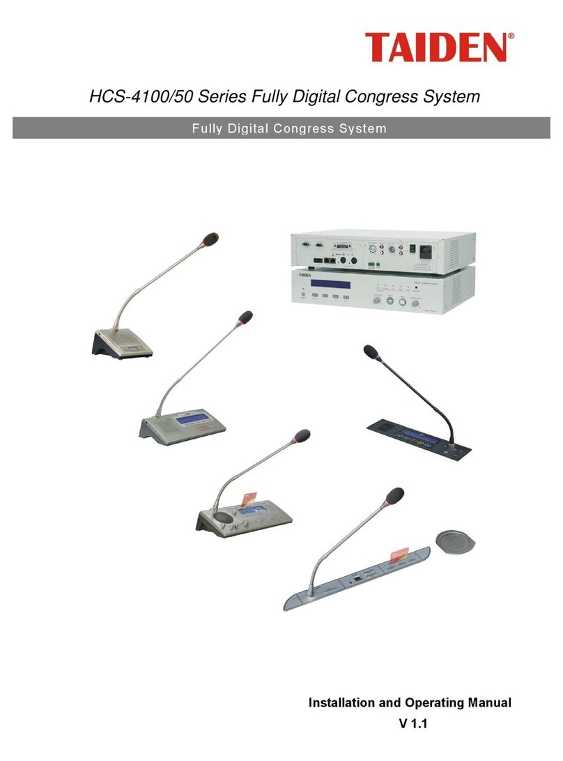
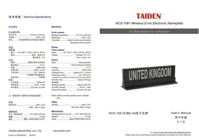
Taiden HCS-4393G2 User manual

Conference Sign-in System
InstallationandOperatingManual
V1.1
Conference Si
g
n-in S
y
stem

I
Remark:
All rights reserved for translation, reprint or reproduction
Contents may change without prior announcement
All technical specifications are guideline data and no guaranteed features
We are not responsible for any damage caused by improper use of this manual
The equipment must be connected to earth!
This product conforms to the rules of the European directive 2004/108/EC.
If any detailed information needed, please contact your local agent or TAIDEN Service Center. Any feedback,
advice and suggestion about the products is appreciated
TAIDEN is the registered trademark of TAIDEN Co., Ltd.

II
Important Safety Instruction
1. Read these instructions.
2. Keep these instructions.
3. Heed all warnings.
4. Follow all instructions.
5. Do not use this apparatus near water.
6. Clean only with dry cloth.
7. Do not block any ventilation openings. Install in
accordance with the manufacturer’s instructions.
8. Do not install near any heat sources such as radiators,
heat registers, stoves, or other apparatus (including
amplifiers) that produce heat.
9. Do not defeat the safety purpose of the polarized or
grounding-type plug. A polarized plug has two blades
with one wider than the other. A grounding type plug
has two blades and a third grounding prong. The wide
blade and the third prong are provided for your safety.
If the provided plug does not fit into your outlet,
consult an electrician for replacement of the obsolete
outlet.
10. Protect the power cord from being walked on or
pinched particularly at plugs, convenience
receptacles, and the point where they exit from the
apparatus.
11. Only use attachments/accessories specified by the
manufacturer.
12. Use only with the cart, stand, tripod, bracket, or table
specified by the manufacturer, or sold with the
apparatus. When a cart is used, use caution when
moving the cart/apparatus combination to avoid injury
from tip-over.
13. Unplug this apparatus during lightning storms or
when unused for long periods of time.
14. Refer all servicing to qualified service personnel.
Servicing is required when the apparatus has been
damaged in any way, such as power-supply cord or
plug is damaged, liquid has been spilled or objects
have fallen into the apparatus, the apparatus has
been exposed to rain or moisture, does not operate
normally, or has been dropped.
15. Do not place the equipment on any uneven or
unstable stand; original product package or
appropriate package should be used to avoid damage
caused by strong impacts during transportation.
16. Power supply cords:
AC 110 V-120 V 60 Hz or AC 220 V-240 V 50 Hz
17. For service, please contact the nearest TAIDEN
Service Center.
18. All TAIDEN products are guaranteed for definite time
(see the WARRANTY CARD for details) excluding the
following cases:
A. All damage or malfunction caused by human
negligence;
B. Damage or malfunction caused by improper
operating by operator;
C. Parts damage or loss caused by disassembling
the product by non-authorized personnel.
19. Use ONLY specified connection cable to connect the
system equipment.
20. Upon receipt of the product, please fill out the
Warranty Card enclosed and post it to TAIDEN
Service Center.
The lightning flash with an arrowhead symbol, with
an equilateral triangle, is intended to alert the user
to the presence of uninsulated ‘dangerous voltage’
within the products enclosure that may be of
sufficient magnitude to constitute a risk of electric
shock to persons.
CAUTION: To reduce the risk of electric shock,
DO NOT open covers, no user serviceable parts
inside. Refer servicing to qualified service
personnel only.
TO REDUCE THE RISK OF FIRE OR ELECTRIC SHOCK, DO
NOT EXPOSE THIS EQUIPMENT TO RAIN OR MOISTURE.
TO REDUCE THE RISK OF FIRE OR ELECTRIC SHOCK, DO
NOT EXPOSE THIS EQUIPMENT TO RAIN OR MOISTURE.
CAUTION: DO NOT use alcohol, ammonia or
petroleum solvents or abrasive cleaners to
clean the devices.

III
Important Safety Instruction
The exclamation mark within an equilateral triangle
is intended to alert the user to the presence of
important operating and maintenance (servicing)
instructions in the literature accompanying the
appliance.
Attention: Installation should be performed by
qualified service personnel only in accordance
with the National Electrical or applicable local
codes.
Power Disconnect: Units with or without ON – OFF
switch have power supplied to the unit whenever
the power cord is inserted into the power source;
however, the unit is operational only when the ON
– OFF switch is in the ON position. The power cord
is the main power disconnect for all units
WARNING: The apparatus should be
connected to a mains socket outlet with a
protective earthing connection.
WARNING: To reduce the risk of fire or
electric shock, DO NOT expose units to rain
or moisture.

IV
Content
Installation & User Guide........................................................................................................... V
Chapter 1: Contactless Conference Sign-in Machine.................................................................1
1.1 Overview ...........................................................................................................................................................1
1.2 Installation and connection ...............................................................................................................................2
1.2.1 Direction of the passage..............................................................................................................................................2
1.2.2 Cabinet interface .........................................................................................................................................................2
1.2.3 Connection ..................................................................................................................................................................2
1.3 FAQ...................................................................................................................................................................3
1.4 Matters need attention ......................................................................................................................................4
1.5 Troubleshooting ................................................................................................................................................6
Chapter 2: Sign-in Information Display Screen...........................................................................7
2.1 Overview ...........................................................................................................................................................7
2.2 Connection........................................................................................................................................................8
2.3 Operation ..........................................................................................................................................................8
2.4 Touch Screen Driver Installation and Calibration Instruction............................................................................9
2.4.1 Touch Screen Driver Installation..................................................................................................................................9
2.4.2 Touch Screen Calibration ..........................................................................................................................................10
2.5 Troubleshooting and notes .............................................................................................................................11
Chapter 3: Contactless IC-Card Encoder and Long-distance Contactless IC-Card.................. 12
3.1 Overview .........................................................................................................................................................12
3.2 Performance ...................................................................................................................................................12
3.3 Installation.......................................................................................................................................................12

V
Installation & User Guide
About this manual
This manual is a comprehensive guide for TAIDEN
Conference Sign-in System, mainly includes functions
and interface descriptions of Contactless Conference
Sign-in Machine HCS-4393G2, Sign-in Information
Display Screen HCS-4393G/D and Contactless
IC-Card Encoder HCS-4345NTK, connection and
installation of system devices, system setup and
operation instructions.
The manual is divided into the following chapters:
Chapter 1: Contactless Conference Sign-in
Machine
An overview of the composition, installation and
matters need attention of Contactless Conference
Sign-in Machine HCS-4393G2.
Chapter 2: Sign-in Information Display Screen
Detailed descriptions of features, operation and
matters need attention of Sign-in Information Display
Screen HCS-4393G/D.
Chapter 3: Contactless IC-Card Encoder and
Long-distance Contactless IC-Card
Detailed descriptions of features, operation and
matters need attention of Contactless IC-Card Encoder
HCS-4345NTK and Long-distance Contactless IC-Card
HCS-3924S.
This manual is applicable to:
Contactless Conference Sign-in Machine
HCS-4393G2 Contactless Conference Sign-in Machine
Sign-in Information Display Screen
HCS-4393G/D Sign-in Information Display Screen
Contactless IC-Card Encoder
HCS-4345NTK Contactless IC-Card Encoder
Long-distance Contactless IC-Card
HCS-3924S Long-distance Contactless IC-Card

1
Chapter 1: Contactless Conference Sign-in Machine
1.1 Overview
Contactless Conference Sign-in Machine HCS-4393G2
(hereinafter referred to as "sign-in machine") is a high
performance electronic tag read/write device, it can
read/write all popular electronic tags which support
ISO/IEC15693 standard. By adopting high
performance 32-bit processor and today's advanced
anti-collision algorithm, powerful tag processing is
realized with stable performance and strong capacity of
resisting disturbance. It is mainly used for personal
identification, conference sign-in, library management,
access control, goods tracking and anti-fake,
warehouse and logistics, and other areas.
Features:
High performance 32-bit processor
Tag processing speed: 40~50 pieces/second
RF output power > 4 W
Induction distance > 120 cm
4 channels infrared control to determine in and out
SMA interface can be connect to 50 Ωstandard RF
ID antenna
Support active/passive mode
Specifications:
Working
frequency 13.56 MHz ± 7 KHz
Standard ISO/IEC15693,
ISO18000-3
Induction distance ≥120 cm (be related to tag)
IR quantity 4 pairs
Communication RS232/RS485
Antenna interface SMA
Output
impedance 50 Ω
Working current <1.2 A
Working voltage 12 V
Technical parameter
Output power >4 W
Working
temperature -25℃~60℃
Storage
temperature -40℃~85℃
Environment
al parameter
Humidity 30%~95% RH
Dimension 152×54×10 cm
Weight 29 kg
Physical
parameter
Color Light grey
Figure 1.1 System overview

2
1.2 Installation and connection
1.2.1 Direction of the passage
Figure 1.2 Sign-in machine
Sign-in machine is composed of one major antenna
and one minor antenna, the minor antenna connects to
the major antenna with SMA connector. The IR bezel of
both antennas should be placed towards the inside of
passage. Antennas should keep distance from metal or
other RF devices, so as not to affect reading effect and
distance.
1.2.2 Cabinet interface
Figure 1.3 Cabinet interface of the major antenna
1. To RS-232 cable (5-cord aviation connector)
2. To synchro-control cable (4-cord aviation connector)
3. To power and indicator cable (6-cord aviation
connector)
4. To the minor antenna (SMA connector)
1.2.3 Connection
1. RS-232 cable
Connect aviation plug of RS-232 cable to 5-cord
aviation connector ①of the major antenna, and DB-9
connector of RS-232 cable to COM port of PC.
2. Synchro-control cable (optional)
Synchro-control cable is needed when more than one
sign-in machines working together in a small area to
avoid interference. One of the sign-in machines should
be configured as master and the others as slave by
software setup.
Synchro-control cable is Y type and has three
connectors, connect one aviation plug of
synchro-control cable to 4-cord aviation connector of②
the major antenna, the other two connectors connect to
the previous and the next sign-in machine, and all
sign-in machines can be connected in daisy-chain.
When connecting synchro-control cable, please use
parallel connection, i.e. red line connecting to red line,
and black line connecting to black line. After
connecting synchro-control cable, please set sign-in
machine to synchro mode by software.
3. Power and indicator cable
Connect aviation plug of power and indicator cable to
6-cord aviation connector ③of the major antenna.
4. To the minor antenna
Connect SMA plug of the minor antenna to SMA
connector of the major antenna.④
Warning:
)Please power off before connecting cables,
hot-line work is prohibitted.
Note:
)In synchro-control mode, the distance
between two adjacent sign-in machines
should be larger than 1 meter to avoid
interference.

3
1.3FAQ
1. Direct judgement is not accurate in bi-directional
access
When IR function is enabled, only one direction should
be accessed at one time and avoid bi-directional
access, as the following figure:
2. Tag detection is not accurate when more than
one person pass through the passage
side-by-side
When more than one person pass through the passage,
they should pass through one by one and avoid
side-by-side, as the following figure:
3. No reaction when pass through too slow
Maximum time limit is set when passing through. If
walking too slow and exceed maximum time limit,
direction judgement will be disclaimed.
4. It will alarm when quickly reentry after pass
through
Passage filters tags when detecting, how long does
filtering take is decided by "tag filtering time". In the
period of tag filtering time, the same tag is processed
only one time. If the person passes through the
passage and then quickly reentry within "tag filter time",
reentry tag will be filtered, and causing alarm.
To ensure the accuracy of direction judgement,
immediate reentry is prohibited. Please wait 5 to 10
seconds after pass through.
5. Other person's information is displayed
First-come-first-serve rule is applied in tag detection.
When more than one person pass through the passage,
the information of the first detected tag will be reported.
If some one stands inside detection area, when other
person passes through the passage, the tag
information of whom stands inside detection area will
be reported.
6. How to deal with the case that one person takes
more than one card
"One person-one card, more cards-waiting time-out"
rule is applied in tag detection, i.e., when one person
passes through the passage, one tag information will
be reported, and the rest tag information will be saved
in cache and waiting for the next person or later
reported as time-out information when reached "tag
time-out".
When one person takes more than one card, the first
detected tag information will be reported, and the rest
tag information will be reported as time-out information.
Note:
)Standing inside detection area for a long time
should be avoided!!!
Note:
)Normal walking speed is recommended,
please do not stop inside the passage.

4
1.4Mattersneedattention
The distance between antenna and computer
should be larger than 140 cm, otherwise he/she
may miss his/her information when passes
through the passage.
If not using synchro-control cable, the distance
between two passages should be larger than 6 m;
when using synchro-control cable, the distance
should be larger than 1 m.
The width of the passage should be 90 cm and
avoid two persons pass through the passage
side-by-side.
Prior to the start of the meeting, meeting
manager should be informed to keep order,
participants passing through the passage
side-by-side is prohibited. If tag detection of the
previous participant is not successful, then block
the following participants. Ask this participant to
pass through the passage again until his/her
card is detected successfully.
Prior to the start of the meeting, all participants
should be informed to pass through the passage,
otherwise he/she would be regarded as absent;
Officers of the meeting should take cards without
IC to avoid mis-detection of the officers of the
meeting;
Participants who has passed through the
passage should not stay near the passage,
otherwise he/she will be set as departure when
the following participants pass through the
passage;
Prior the start of the meeting, participants should
be informed that his/her card can be recognized
by the system automatically when he/she pass
through the passage;
Immediate reentry after pass through is
prohibited, please wait 5 to 10 seconds after pass
through.

5
Note:
)The IC card should be keep 50 cm - 160cm
high from the ground;
)The IC card should NOT be kept parallel to
the ground;
)The IC card should NOT be fully placed
together with metal items, such as key,
cigarette case, mobile phone, mobile hard
disk, etc.
)The IC card should NOT be placed togethe
r
with monthly ticket, membership card,
identification card, etc.
)The IC card should be protected by hard card
j
acket and avoid buckling, otherwise it may
shorten detection distance or even detection
failure.
)Sign-in machine should be placed far from
large metal objects and reinforced concrete
wall;
)Sign-in machine is a RF device, and may be
j
ammed by other RF devices with simila
r
frequency or low frequency and high power.
Therefore, it should be kept away from
interfering resources.
)When direction judgement function is
enabled, to ensure the accuracy of direction
j
udgement, two persons pass through the
passage in opposite direction or side-by-side
should be avoided. When several persons
pass through the passage one by one, they
should keep a space larger than 30 cm.

6
1.5 Troubleshooting
Fault symptom Fault cause
1. Communication is abnormal. 1. Using non-cross serial cable;
2. Error serial port bit rate or error parameters, default
value is 38400 bps with 8 data bits, 1 stop bit, and no
parity check;
3. Serial port has not opened;
4. Serial port is occupied by other applications.
2. After modifying system parameters, it
works normally. But the modifications
are lost when power off.
The modifications of system parameters are saved in
RAM, after modification, corresponding command should
be executed to save modifications into FLASH.
3. It does not detect tag. 1. Check working mode. In passive mode, detection
command should be executed to detecting.
2. Tag is still;
3. There are metal objects around tag or antenna.
4. Return value does not meet the
requirement.
1. Flag bit of the command is error, please configure
correct command according to protocol;
2. Tag is still;
3. There are more than one tags in detection area and no
UID is appointed;
4. Not enough command parameter;
5. Tag type does not match.
5. Detection distance is too short. 1. There are metal objects around tag or antenna;
2. The working frequency of tag deviate too much from
13.56MHz;
3. Tags overlap each other causing interference;
4. Environmental electromagnetic interference;
5. Mutual interference between two pair of antenna。
If above troubleshootings do not work, please contact our dealers or after-sales service staff.

7
Chapter 2: Sign-in Information Display Screen
2.1 Overview
TAIDEN sign-in information display screen adopts
integrated cabinet, based on touch devices for ease of
use and intuitive, abandoned complicated operation of
traditional mouse and keyboard, the user does not
need a complicated operation, simply click on the touch
screen, and it can display sign-in information. Display
content can be setup by meeting sign-in system
software, specific setting method please refer to
software instruction.
The sign-in information display screen is composed of
a LCD module, a touch screen, a cabinet, and a
computer, where the computer will be provided by
users themselves.
Figure 2.1 Sign-in information display screen
Specifications:
Type Resistance screen
Resolution 4096×4096
Touch panel
Power
consumption 1 W
Dimension 19 inch
Brightness 250 cd/m2
Power
consumption 49 W
Contrast 1000:1
Resolution 4096×4096
LCD
Visual angle 150°/140°
Dimension 50×44×143 cm
Weight 34 kg

8
2.2 Connection
There are 8 cables inside the cabinet:
Connect all cables to computer and put the computer
into cabinet.
2.3 Operation
1.Power on
Power on by pressing the red switch on the right side.
Press the green button on the left side to start-up
sign-in information display screen.
2.Mouse and keyboard
Connect mouse and keyboard to USB port and use
them when needed.

9
2.4 Touch Screen Driver Installation and
Calibration Instruction
2.4.1 Touch Screen Driver Installation
Connected host, plug in the power, press the switch,
double-click the touch screen driver installation
program “setup.exe” to install.
The drivers for the following operating systems:
Windows XP
Windows 2000
Windows Me
Windows 98
Windows 95
Windows NT 4.0
Windows VISTA
Windows 7
Installation:
1. Driver installation location without the user changes
the default installation in C: \ Program Files \
TouchScreen;
2. Click "next" to install to local folder or you can
change to install to a different folder. Then, choose
the setup type that best suits your needs;
3. Click "Install" to continue;
4. Please wait for install completed, all process may
take several minutes;

10
5. After installation, it will create the desktop and start
menu shortcuts.
2.4.2 Touch Screen Calibration
Start touch screen driver “TouchScreenSetup” to
calibrate.
1. Setup operation language: English or Chinese;
2. Select serial port in serial device manager;
3. Set up calibration in setup menu, default is ok for
general user;
4. Select calibration type (4 points / 9 points / 25 points),
and then click "Calibration" to start;
5. Click the screen to calibrate the touch screen;
6. After calibration, click "Line Test" to check dead
zone.
7. Calibration is complete, double-click the screen or
press the <Enter> key to save the calibration data.

11
2.5 Troubleshooting and notes
1. Touch monitor touch calibration
Install the driver after the computer restarts, click on the
desktop “TouchScreenSetup” icon or click “Start” -
“program” - “TouchSreen” - “TouchSetup” button in turn,
click "Calibration" and follow the four points that appear
on the screen in order to be corrected.
2. How to remove the touch driver?
Click the “Start” - “Settings” -“Control Panel” - “Add /
Remove Programs” - “Install / Uninstall” tab select the
box point “TouchScreen Driver for Windows” - Single
click the “Add / Remove” follow the prompts to restart
your computer or uninstall.
3. When to re-calibrate the touch screen?
Change the display resolution;
Replace the computer host or display;
After clearance.
4. Why is mouse move automatically without
clicking?
Touch screen may be oppressed by external;
Ground signal interference caused by bad.
5. No Signal on Screen
Check the power light is lit or not, if not, may be
the monitor has no power;
Please check the monitor VGA is connected. If
the data cable is not connected then the power,
the display will show no signal, please connect
the data cable from the new.
6. No response after touching
Driver is installed, install the correct driver;
Computer serial port is operating properly, check
the serial port serial port and driver settings are
correctly;
Main power supply is normal, check the host
power supply. Replace the main test;
Protective film does not tear up, tear up the
protective film after the test.
7. Click is not the same position of your fingers
touching
Whether the incorrect calibration, re-calibration,
if not enough, please do 25 points calibration;
After changing the display resolution is not
calibrated correctly re-positioning;
If you use 3 to 4 years, resistance screen may
be damaged. Need to replace the new.

12
Chapter 3: Contactless IC-Card Encoder and Long-distance
Contactless IC-Card
3.1 Overview
Contactless IC-Card Encoder HCS-4345NTK is based
on ISO 15693 standard, working at 13.56 MHz with
short detection distance. This card writer is cooperated
with computer.
This Encoder has all functions defined in ISO 15693
standard, such as moving recognition, multiple tag
recognition, with collision prevention function, it can
recognize three cards at one time, it can read/write
three data blocks at one time. As a standard table-top
high-frequency card writer, it is suitable for various
applications.
Figure 3.1 Contactless IC-Card Encoder HCS-4345NTK
Figure 3.2 Contactless IC-Card
3.2 Performance
zWorking frequency: 13.56MHz
zStandard: ISO 15693
zSupported card type: Tag-it HF-I, TI256 card or other
ISO15693 standard compatible cards
zAll functions defined in ISO15693 standard
zRead/write/lock multiple data block function
zCollision prevention function, it can read three cards
at one time
zDetection distance: 10 cm
zCommunication port: USB
3.3 Installation
1. Put Contactless IC-Card Encoder HCS-4345NTK on
the table, its appearance is shown as figure3.1;
2. This Encoder is equipped with USB cable and can
be connected with computer;
3. Install TAIDEN conference application in the
computer and run it. All ISO 15693 standard defined
functions can be realized.
For the detail of software operation, please refer to
software user's manual.
Note:
)When using Contactless IC-card Encoder
HCS-4345NTK, please keep it away from
strong magnetizing field;
)When using Contactless IC-card Encoder
HCS-4345NTK, please do not place it on
metal table or put metal objects on it, it is
recommended that no metal objects should
be placed within 5 cm around it.

www.taidem.com
TAIDEN INDUSTRIAL CO.,LTD.
Copyright by TAIDEN
Last Revision: 01/2013
This manual suits for next models
3
Table of contents
Other Taiden Conference System manuals

Taiden
Taiden HCS-4800 Series User manual

Taiden
Taiden HCS-4100/50 Series User manual

Taiden
Taiden HCS-5300 User manual

Taiden
Taiden hcs-8300 User manual

Taiden
Taiden HCS-4100MA/50 User manual

Taiden
Taiden HCS-3600 Series User manual

Taiden
Taiden HCS-3938C User manual

Taiden
Taiden HCS-4100MC/50 User manual

Taiden
Taiden HCS-5300MA/80 User manual

Taiden
Taiden HCS-8600 Series User manual